Frigidaire FFGF3012TW Guide d'installation
- Catégorie
- Micro-ondes
- Taper
- Guide d'installation

1
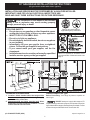
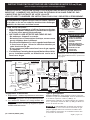
30" GAS RANGE INSTALLATION INSTRUCTIONS
(For gas venturi models with electric ignition)
INSTALLATION AND SERVICE MUST BE PERFORMED BY A QUALIFIED INSTALLER.
IMPORTANT: SAVE FOR LOCAL ELECTRICAL INSPECTOR'S USE.
READ AND SAVE THESE INSTRUCTIONS FOR FUTURE REFERENCE.
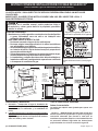
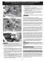
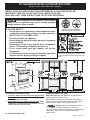
Clearances and Dimensions
1. Location—Check location where the range will be
installed. Check for proper electrical and gas supply,
and the stability of the floor.
2. Dimensions that are shown must be used. Given
dimensions provide minimum clearance. Contact
surface must be solid and level.
Provide Proper Fuel Type
Before Proceeding: Your range is preset to operate on
natural gas.
DO NOT attempt to convert this range to LP/
Propane settings without the proper LP/Propane conversion
kit provided with the range or obtained from your dealer. Follow
all instructions provided with the LP Conversion Kit.
Español - Páginas 9-16
If the information in this manual is not followed
exactly, a fire or explosion may result causing property
damage, personal injury or death.
FOR YOUR SAFETY:
— Do not store or use gasoline or other flammable vapors
and liquids in the vicinity of this or any other appliance.
— WHAT TO DO IF YOU SMELL GAS:
• Do not try to light any appliance.
• Do not touch any electrical switch; do not use any phone
in your building.
• Immediately call your gas supplier from a neighbor's
phone. Follow the gas supplier's instructions.
• If you cannot reach your gas supplier, call the fire
department.
— Installation and service must be performed by a qualified
installer, service agency or the gas supplier.
Note: For appliances installed in the
Commonwealth of Massachusetts see
page 2.
Refer to your serial plate for
applicable agency certification
p/n 316469107 EN/SP (0810)

2
30" GAS RANGE INSTALLATION INSTRUCTIONS
(For gas venturi models with electric ignition)
Important Notes to the Installer
1. Read all instructions contained in these installation
instructions before installing range.
2. Remove all packing material from the oven compartments
before connecting the gas and electrical supply to the
range.
3. Observe all governing codes and ordinances.
4. Be sure to leave these instructions with the consumer.
Important Note to the Consumer
1. Keep these instructions with your Use & Care Guide for
future reference.
IMPORTANT SAFETY INSTRUCTIONS
Installation of this range must conform with local codes or, in
the absence of local codes, with the National Fuel Gas Code
ANSI Z223.1—latest edition when installed in the United
States.
When installed in a manufactured (mobile) home, installation
must conform with the Manufactured Home Construction and
Safety Standard, Title 24 CFR, Part 3280 [formerly the Federal
Standard for Mobile Home Construction and Safety, Title 24,
HUD (Part 280)] or, when such standard is not applicable, the
Standard for Manufactured Home Installations, ANSI/NCSBCS
A225.1, or with local codes.
This range has been design certified by CSA International. As
with any appliance using gas and generating heat, there are
certain safety precautions you should follow. You will find them
in the Use & Care Guide, read it carefully.
• Be sure your range is installed and grounded properly
by a qualified installer or service technician.
• This range must be electrically grounded in
accordance with local codes or, in their absence,
with the National Electrical Code ANSI/NFPA No .70—
latest edition when installed in the United States.
See Grounding Instructions on page 5.
• Before installing the range in an area covered with
linoleum or any other synthetic floor covering, make
sure the floor covering can withstand heat at least
90°F above room temperature without shrinking,
warping or discoloring. Do not install the range over
carpeting unless you place an insulating pad or sheet of
1/4-inch thick plywood between the range and carpeting.
• Make sure the wall coverings around the range can
withstand the heat generated by the range.
• Do not obstruct the flow of combustion air at the oven
vent nor around the base or beneath the lower front
panel of the range. Avoid touching the vent openings or
nearby surfaces as they may become hot while the oven
is in operation. This range requires fresh air for proper
burner combustion.
Never leave children alone or unattended
in the area where an appliance is in use. As children grow,
teach them the proper, safe use of all appliances. Never leave
the oven door open when the range is unattended.
Stepping, leaning or sitting on the doors
or drawers of this range can result in serious injuries and
can also cause damage to the range.
• Do not store items of interest to children in the
cabinets above the range. Children could be seriously
burned climbing on the range to reach items.
• To eliminate the need to reach over the surface
burners, cabinet storage space above the burners
should be avoided.
• Adjust surface burner flame size so it does not
extend beyond the edge of the cooking utensil.
Excessive flame is hazardous.
• Do not use the oven as a storage space. This creates
a potentially hazardous situation.
• Never use your range for warming or heating the
room. Prolonged use of the range without adequate
ventilation can be dangerous.
• Do not store or use gasoline or other flammable
vapors and liquids near this or any other appliance.
Explosions or fires could result.
• Reset all controls to the "off" position after using a
programmable timing operation.
FOR MODELS WITH SELF-CLEAN FEATURE:
• Remove broiler pan, food and other utensils before
self-cleaning the oven. Wipe up excess spillage. Follow
the cleaning instructions in the Use & Care Guide.
DO NOT MAKE ANY ATTEMPT TO
OPERATE THE ELECTRIC IGNITION OVEN DURING AN
ELECTRICAL POWER FAILURE. RESET ALL OVEN
CONTROLS TO "OFF" IN THE EVENT OF A POWER
FAILURE.
The electric ignitor will automatically re-ignite the oven burner
when power resumes if the oven thermostat control was left
in the "ON" position.
When an electrical power failure occurs during use, the
surface burners will continue to operate.
During a power outage, the surface burners can be lit with a
match. Hold a lighted match to the burner, then slowly turn
the knob to the LITE position. Use extreme caution when
lighting burners this way.
Special instructions for appliances installed in the
Commonwealth of Massachusetts: This appliance can only
be installed in the Commonwealth of Massachusetts by a
Massachusetts licensed plumber or gas fitter. When using a
flexible gas connector, it must not exceed 3 feet (36 inches)
in length. A "T" handle type manual gas valve must be
installed in the gas supply line to this appliance.
• Air curtain or other overhead range hoods, which operate
by blowing a downward air flow on to a range, shall not be
used in conjunction with gas ranges other than when the
hood and range have been designed, tested and listed by
an independent test laboratory for use in combination with
each other.

3
30" GAS RANGE INSTALLATION INSTRUCTIONS
(For gas venturi models with electric ignition)
Before Starting
Tools You Will Need
For leveling legs and Anti-Tip Bracket:
• Adjustable wrench or channel lock pliers
• 5/16" Nutdriver or Flat Head Screw Driver
• Electric Drill & 1/8" Diameter Drill Bit (5/32" Masonry Drill
Bit if installing in concrete)
For gas supply connection:
• Pipe wrench
For burner flame adjustment:
• Phillips head and
blade-type screwdrivers
For gas conversion (LP/Propane or Natural):
• Open end wrench - 1/2"
Additional Materials You Will Need
• Gas line shut-off valve
• Pipe joint sealant that resists action of LP/Propane gas
• A new flexible metal appliance conduit (1/2" NPT x 3/4"
or 1/2" I.D.) must be design certified by CSA International.
Because solid pipe restricts moving the range we
recommend using a new flexible conduit (4 to 5 foot
length) for each new installation and additional
reinstallations.
• Always use the (2) new flare union adapters (1/2" NPT x
3/4" or 1/2" I.D.) supplied with the new flexible appliance
conduit for connection of the range.
Normal Installation Steps
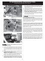
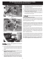
1. Anti-Tip Bracket Installation Instructions
Important Safety Warning
To reduce the risk of tipping of the range, the range must be
secured to the floor by properly installed anti-tip bracket and
screws packed with the range. Failure to install the anti-tip
bracket will allow the range to tip over if excessive weight is
placed on an open door or if a child climbs upon it. Serious
injury might result from spilled hot liquids or from the range
itself.
If range is ever moved to a different location, the anti-tip
brackets must also be moved and installed with the range.
Instructions are provided for installation in wood or cement
fastened to either the floor or wall. When installed to the wall,
make sure that screws completely penetrate dry wall and are
secured in wood or metal. When fastening to the floor or wall,
be sure that screws do not penetrate electrical wiring or
plumbing.
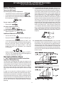
A. Locate the Bracket Using the Template - (Bracket may
be located on either the left or right side of the range. Use
the information below to locate the bracket if template is
not available). Mark the floor or wall where left or right side
of the range will be located. If rear of range is against the
wall or no further than 1-1/4" from wall when installed, you
may use the wall or floor mount method. If molding is
installed and does not allow the bracket to fit flush against
the wall, remove molding or mount bracket to the floor. For
wall mount, locate the bracket by placing the back edge
of the template against the rear wall and the side edge of
template on the mark made referencing the side of the
range. Place bracket on top of template and mark location
of the screw holes in wall. If rear of range is further than
1-1/4" from the wall when installed, attach bracket to the
floor. For floor mount, locate the bracket by placing back
edge of the template where the rear of the range will be
located. Mark the location of the screw holes, shown in
template.
B. Drill Pilot Holes and Fasten Bracket - Drill a 1/8" pilot
hole where screws are to be located. If bracket is to be
mounted to the wall, drill pilot hole at an approximate 20°
downward angle. If bracket is to be mounted to masonry
or ceramic floors, drill a 3/16" pilot hole 1-3/4" deep. The
screws provided may be used in wood or concrete material.
Use a 5/16" nut-driver or flat head screwdriver to secure the
bracket in place.

4
30" GAS RANGE INSTALLATION INSTRUCTIONS
(For gas venturi models with electric ignition)
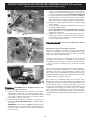
C. Level and Position Range - Level range by adjusting the
(4) leveling legs with a wrench. Note: A minimum clearance
of 1/8" is required between the bottom of the range and the
leveling leg to allow room for the bracket. Use a spirit level
to check your adjustments. Slide range back into position.
Visually check that rear leveling leg is inserted into and
fully secured by the Anti-Tip Bracket by removing lower
panel or storage drawer. For models with a warmer drawer
or broiler compartment, grasp the top rear edge of the
range and carefully attempt to tilt it forward.
2. Provide an adequate gas supply.
This appliance is pre-set to operate on 4" natural gas manifold
pressure. The pressure regulator MUST be connected in
series with the gas supply line. If the LP/Propane conversion
kit has been used, follow instructions provided with the kit for
converting the pressure regulator to LP/Propane use. The LP
kit can be found on the back side of the range (some models).
Care must be taken during installation of range not to obstruct
the flow of combustion and ventilation air.
For proper operation, the maximum inlet pressure to the
regulator should be no more than 14 inches of water column
pressure. The inlet pressure to the regulator must be at least
1 inch greater than regulator manifold pressure. Examples: If
regulator is set for natural gas 4 inch manifold pressure, inlet
pressure must be at least 5 inches; if regulator has been
converted for LP/Propane gas 10 inch manifold pressure, inlet
pressure must be at least 11 inches.
Leak testing of the appliance shall be conducted according to
the instructions in step 4g.
The gas supply line should be 1/2" or 3/4" I.D.
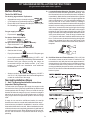
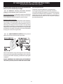
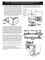
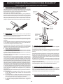
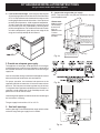
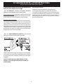
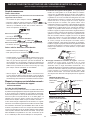
3. Seal wall openings.
Seal any openings in the wall behind the range and in the floor
under the range after gas supply line is installed.
Fig. 4a
Fig. 4b
Fig. 4c
Wall
Edge
23"
15"
2"
7"
11-1/2"
10-1/2"
Recommended area for
120V outlet on rear of
wall and area for thru
the wall connection of
pipe stub and shut-off
valve is shaded area.
Recommended area for thru
the floor connection of
pipe stub and shut-off valve.
Centerline
of range
Centerline
of range
C
L
4. Connect the range to the gas supply.
NOTE: To prevent leaks use pipe joint sealant on all male
(outside) pipe threads.
*Please note:
Models without
self-cleaning
feature may
have an
additional 4 to
7 inches
clearance from
the floor.
*

5
30" GAS RANGE INSTALLATION INSTRUCTIONS
(For gas venturi models with electric ignition)
Do not use flame to check for gas leaks.
Checking Manifold Gas Pressure
Disconnect the range and its individual shut-off valve from the
gas supply piping system during any pressure testing of that
system at test pressures greater than 14" of water column
pressure (approximately 1/2" psig).
The appliance must be isolated from the gas supply piping
system by closing its individual manual shut-off valve during
any pressure testing of the gas supply piping system at test
pressures equal to or less than 14" of water column pressure
(approximately 1/2" psig).
If it should be necessary to check the manifold gas pressure,
connect manometer (water gauge) or other pressure device to
the top burner right rear orifice. Using a rubber hose with inside
diameter of approximately 1/4," hold tubing down tight over
orifice. Turn burner valve on.
For an accurate pressure check have at least two (2) other top
burners burning. Be sure the gas supply (inlet) pressure is at
least one inch above specified range manifold pressure. The
gas supply pressure should never be over 14" water column.
When properly adjusted for Natural Gas the manifold pressure
is 4." (For LP/Propane Gas the manifold pressure is 10.")
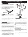
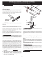
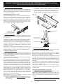
DO NOT allow regulator to turn on pipe
when tightening fittings.
a) Install an external manual gas shut-off valve to gas supply
line in an accessible location outside of the range. Be sure
you know where and how to shut off the gas supply to the
range.
b) Install 1/2" flare union adapter to pressure regulator using
NO MORE THAN 15ft./lbs. of torque
NOTE: Be sure to stabilize the left side of the pressure
regulator with adjustable wrench before tightening ANY
fittings to the pressure regulator (Refer to Fig. 4d).
c) Tighten the gas supply fitting and/or appliance conduit to
flare union on the right side of the pressure regulator using
NO MORE THAN 15ft./lbs. of torque.Be sure to stabilize
“ ON ”
Fig. 4d
Fig. 4e
Fig. 4f
the 1/2" flare union adapter with an adjustable wrench
before tightening the gas supply fitting and/or appliance
conduit (Refer to Fig. 4e).
d) Install flare union adapter to external manual shut-off valve.
e) Attach appliance conduit to flare union on shut-off valve.
f) Make sure service shut-off valve on pressure regulator
is in the "ON" position (See Fig. 4f).
g) Check for leaks. Turn the gas supply on to the range and
use a liquid leak detector at all joints and conduits to
check for leaks in the system.

6
30" GAS RANGE INSTALLATION INSTRUCTIONS
(For gas venturi models with electric ignition)
Where a standard two-prong wall receptacle is encountered,
it is the personal responsibility and obligation of the customer
to have it replaced with a properly grounded three-prong wall
receptacle.
DO NOT, UNDER ANY CIRCUMSTANCES, CUT OR REMOVE
THE THIRD (GROUND) PRONG FROM THE POWER CORD.
5. Read these electrical connection details first
then connect electricity to range.
Before servicing, disconnect electrical
supply at circuit breaker, fuse or power cord.
Electric Requirements: A dedicated, properly grounded and
polarized branch circuit protected by a 15 amp. circuit breaker
or time delay fuse. See serial plate for proper voltage.
Extension Cord Precautions:
Because of potential safety hazards under certain conditions,
we strongly recommend against the use of any extension
cord. However, if you still elect to use an extension cord, it is
absolutely necessary that it be a UL listed 3-wire grounding
type appliance extension cord and that the current carrying
rating of the cord in amperes be equivalent to or greater than
the branch circuit rating. Such extension cords are obtainable
through your local service organization.
Grounding Instructions
The power cord of this appliance is equipped with a
3-prong (grounding) plug which mates with a standard
3-prong grounding wall receptacle to minimize the possibility
of electric shock hazard from this appliance. The customer
should have the wall receptacle and circuit checked by a
qualified electrician to make sure the receptacle is properly
grounded and polarized.
PLEASE READ CAREFULLY! For personal
safety, this product must be properly grounded.

7
30" GAS RANGE INSTALLATION INSTRUCTIONS
(For gas venturi models with electric ignition)
Operation of electric igniters should be checked after range and
supply line connectors have been carefully checked for leaks and
range has been connected to electric power.
Check Surface Burners
To check for proper lighting, push in and turn a surface burner knob
to the LITE position. Each burner should light within four (4)
seconds in normal operation. Once the burner lights, the knob
should be rotated out of the LITE position. Try each knob separately
until all burner valves have been checked.
6.
Operation of Surface Burners
7.
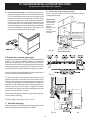
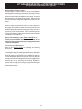
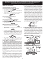
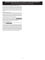
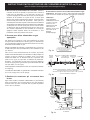
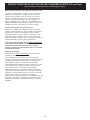
Air adjustment
The air shutter (adjustment) for each of the four top burners is
located at the open end of the venturi tube and sets on the hood
of the valve.
Should the air shutter need adjusting, rotate the air shutter to allow
more or less air into the burner tubes as needed.
If the air is properly adjusted, the flame will be steady, relatively
quiet, and have approximately 1/2" sharp blue cone. (Usually
about the center of air shutter's ajustment.)
If the flame is yellow in color, increase air shutter opening size. If
the flame is a distinct blue, but lifting away from the burner, reduce
the air shutter opening size.
8. Oven Burner Adjustments
Operation of electric igniters should be checked after range and
supply line connectors have been carefully checked for leaks and
range has been connected to electric power.
The oven burner is equipped with an electric control system as
well as an electric oven burner igniter.
These control systems require no adjustment. When the oven is
set to operate, current will flow to the igniter. It will "glow" similar
to a light bulb. When the igniter has reached a temperature
sufficient to ignite gas, the electrically controlled oven valve will
open and flame will appear at the oven burner. There is a time
lapse from 30 to 60 seconds after the thermostat is turned ON
before the flame appears at the oven burner. When the oven
reaches the dial setting, the glowing igniter will go off. The burner
flame will go "out" in 20 to 30 seconds after the igniter goes "OFF."
To maintain any given oven temperature, this cycle will continue
as long as the dial (or display) is set to operate.
After removing all packing materials and literature from the oven:
a) Set oven to BAKE at 300ºF. See Owner's Guide for operating
instructions.
b) Within 60 seconds the oven burner should ignite. Check for
proper flame, and allow the burner to cycle once. Reset
controls to off.
c) Within 60 seconds the broil burner should ignite. Check for
proper flame. Reset controls to off.
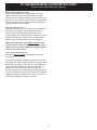
Air Shutter
adjustment
1" Flame
Burner
Baffle
Oven
Burner
Tube
Orifice
Hood
Air
Shutter
Lock
Screw
Air
Shutter
9. Air Shutter-Oven Burner
The approximate flame length of the oven burner is 1 inch
(distinct inner, blue flame).
To determine if the oven burner flame is proper, remove the
oven bottom and burner baffle and set the oven to bake at
300°F.
To remove the oven bottom, remove oven hold down screws at
rear of oven bottom. Pull up at rear, disengage front of oven
bottom from oven front frame, and pull the oven bottom out of
the oven. Remove burner baffle so that the burner flame can be
observe.
If the flame is yellow in color, increase air shutter opening size.
If the flame is a distinct blue, reduce the air shutter opening
size.
To adjust loosen lock screw, reposition air shutter, and tighten
lock screw. Replace oven bottom.
10. Make Sure Range is Level.
Level the range by placing a level horizontally on an oven rack.
Check diagonally from front to back, then level the range by
either adjusting the leveling legs or by placing shims under the
corners of the range as needed.
11. After installation is complete, make sure all controls are
left in the OFF position.

8
30" GAS RANGE INSTALLATION INSTRUCTIONS
(For gas venturi models with electric ignition)
Model and Serial Number Location
The serial plate is located under the lift-up cooktop. When
ordering parts for or making inquires about your range, always
be sure to include the model and serial numbers and a lot
number or letter from the serial plate on your range. Your serial
plate also tells you the rating of the burners, the type of fuel
and the pressure the range was adjusted for when it left the
factory.
Before You Call for Service
Check to make sure the house fuses or circuit breakers for
your range are not blown or open. Refer to the Avoid Service
Checklist and operating instructions in your Owner's Guide. It
may save you time and expense. The list includes common
occurrences that are not the result of defective workmanship
or materials in this appliance.
Refer to the warranty in your
Owner's Guide for our
toll-free service number and address. Please call or
write if you have inquiries about your range product and/
or need to order parts.
Care, Cleaning and Maintenance
Refer to the Owner's Guide for operating and cleaning
instructions.
If removing the range for cleaning or maintenance, shut off gas
supply. Disconnect the gas and electrical supply. If the gas or
electrical supply is inaccessible, lift the appliance slightly at
the front and pull out away from the wall. Pull only as far as
necessary to disconnect the gas and electrical supply. Finish
removing the unit for servicing and cleaning. Reinstall in
reverse order making sure to level the range and check gas
connections for leaks. See Anti-Tip Instructions for proper
anchoring instructions.

9
LA INSTALACIÓN Y CUALQUIER TIPO DE SERVICIO DEBERÁN REALIZARLO UN INSTLADOR
CUALIFICADO.
IMPORTANTE: GUARDE ESTAS INSTRUCCIONES PARA USO DEL INSPECTOR LOCAL Y
PARA REFERENCIAS FUTURAS.
Dimensiones y distancias
1.
Ubicación — Compruebe el lugar de instalación de
la cocina. Compruebe que los suministros de gas y
electricidad son los adecuados y la estabilidad del
suelo.
2. Las dimensiones que se muestran son las que deben
utilizarse. Las dimensiones que se proporcionan
dejarán el espacio mínimo. La superficie de contacto
debe ser sólida y estar nivelada.
Si no se sigue con exactitud la información que se
proporciona en el presente manual, podría producirse fuego o
una explosión y causar graves daños a la propiedad, personales
e incluso la muerte.
PARA SU SEGURIDAD:
—No almacene, ni utilice gasolina o cualquier otro tipo de líquidos
o gases inflamables cerca de esta o de cualquier otra
aplicación de este tipo.
—QUE DEBE HACER SI HUELE A GAS:
• No intente encender ninguna de las aplicaciones.
• No toque ningún interruptor eléctrico, ni utilice los teléfonos
que pueda haber en el edificio.
•
Avise inmediatamente a la empresa de suministro de gas desde un teléfono
en el exterior del edificio. Siga las instrucciones que le proporcione la
empresa de suministro de gas.
• Si no pudiera ponerse en contacto con la empresa de suministro de gas,
avise de inmediato al cuerpo de bomberos de su localidad.
— La instalación y cualquier tipo de servicio deberá realizarlo un
instalador cualificado, una agencia de reparaciones certificada
o la empresa de suministro de gas.
Tipo de combustible adecuado
Antes de conectarlo:
La estufa que adquirio esta ajustada para operar con
gas natural.
NUNCA intente convertir esta cocina para
hacerla funciona con propano/PL sin poseer el juego de
conversión adecuado para llevarlo a cabo que se
suministra o que podrá adquirir en las instalaciones de
su proveedor habitual. Siga todas las instrucciones
proporcionadas con el kit de conversión a gas LP.
English - Pages 1-8
INSTRUCCIONES DE INSTALACIÓN DE COCINAS DE GAS DE 30"
(Para los modelos a gas con tubo Venturi y encendido eléctrico)
p/n 316469107 EN/SP (0810)
Electrodomesticos instalados en el
estado de Massachusetts (vea la página
10).
Refiera a su placa serial para la
certificación aplicable de la agencia
25
3/4"
*5"
30"
30"
30"
30"
18"
Mínimo
*Distancia
mínima
a la pared
lateral
a ambos
lados de
la estufa: 5"
29
1/4"
48"
46
3/8"
36
1/8"
+
-
29 7/8"
36"
al manga
de la puerta
*2
2
2"

10
Instrucciones importantes para el instalador
1. Lea todas las instrucciones que se proporcionan en este manual
de instalación antes de comenzara instalar la cocina.
2. Retire todo el material de embalaje de los compartimentos del
horno antes de conectar el suministro de energía eléctrica y de gas
a la cocina.
3. Siga siempre todos los códigos y normativas locales referentes a
instalación de cocinas.
4. Asegúrese de que el comprador guarde estas instrucciones.
Instrucciones importantes para el comprador
1. Guarde estas instrucciones junto con la
Guía de uso y
mantenimiento para referencias futuras.
INSTRUCCIONES DE SEGUIRDAD IMPORTANTES
La instalación de esta cocina deberá realizarse de acuerdo a la
normativa local o, en caso de que no existiera, de acuerdo a la norma
National Fuel Gas Code ANSI Z223.1—última edición, si la instalación
se realiza en Estados Unidos.
Si la cocina se instala en una casa móvil (caravana), la instalación
deberá realizarse de acuerdo a los estándar de seguridad Manufactured
Home Construction and Safety Standard (Estándar de seguridad y
construcción de casa prefabricadas), Título 24 CFR, Sección 3280
[anteriormente denominada Federal Standard for Mobile Home
Construction and Safety (Estándar federal para seguridad y construcción
de casas prefabricadas), Título 24, HUD (Sección 280)] o, en caso de
que dicho estándar no sea aplicable, deberá seguirse la norma marcada
por el Standard for Manufactured Home Installations, ANSI/NCSBCS
A225.1, o bien, toda la normativa legal existente referente a casas
móviles.
El diseño de esta cocina posee la certificación de CSA International. Del
mismo modo que sucede con otras aplicaciones que utilizan gas y
generan calor, existen ciertas recomendaciones de seguridad que
deberán seguirse siempre. Lea con detenimiento la
Guía de uso y
mantenimiento.
• Asegúrese de que un instalador cualificado o un técnico del servicio
de reparaciones certifica que su cocina se ha instalado y posee una
toma de tierra adecuada.
• Esta cocina deberá poseer una toma de tierra adecuada de acuerdo
a la normativa local o bien, si no existiera, de acuerdo a lo
establecido en el código National Electrical Code ANSI/NFPA Nº
70— última edición si se instala en los Estados Unidos. Consulte las
instrucciones de instalación de la toma de tierra que se proporcionan
en la página 5.
• Antes de instalar la cocina en una zona con recubrimiento de linóleo
o con cualquier otro tipo de suelo sintético, deberá asegurarse de
que el recubrimiento del suelo podrá soportar temperaturas que
superen 32ºC la temperatura ambiente sin que se deterioren, se
resquebrajen o pierdan color. No instale la cocina sobre suelos
enmoquetados a no ser que se coloque un recubrimiento de
protección o una lámina de aislamiento de 1/4” contrachapada para
aislar la cocina de la moqueta.
• Asegúrese de que las cubiertas que se coloquen alrededor de la
cocina puedan soportar el calor que genere la cocina.
• No obstruya el flujo de aire de combustión del orificio de ventilación,
ni alrededor de la base o entre el panel frontal inferior de la cocina.
No toque las aperturas de ventilación, ni las superficies adyacentes
ya que es posible que se calienten en exceso cuando el horno esté
en funcionamiento. Esta cocina requiere aire fresco para que la
combustión del quemador sea la adecuada.
No deje nunca niños solos o desatendidos en
la zona en la que se utilice la aplicación. Conforme vayan
creciendo los niños, deberá explicarles el modo correcto de
utilizar este tipo de aplicaciones. No deje nunca abierta la
puerta del horno si la cocina se va a quedar desatendida.
No se suba, se apoye o se siente en las puertas
o en los cajones de esta cocina ya que podrían producirse
graves daños personales y en la propia cocina.
• No almacene artículos que puedan llamar la atención de
niños en los armarios que haya encima de la cocina. Cualquier
niño podría sufrir quemaduras de gravedad al subirse en la
cocina para alcanzar dichos objetos.
• Para evitar tener que alcanzar cualquier objeto que se
encuentre por encima de los quemadores de la cocina, evite
la instalación de armarios encima de la misma.
• Ajuste el tamaño de la llama del quemador de tal modo que no
rebase los límites de los cazos o utensilios que se utilicen
para cocinar. Una llama excesiva puede ser peligrosa.
• No utilice el horno como lugar de almacenamiento. Si lo hace
pueden producirse situaciones de peligro reales.
• No utilice nunca la cocina para calentar la habitación. Un uso
prolongado de la cocina en espacios sin la ventilación
adecuada es peligroso.
• No almacene gasolina ni cualquier otro tipo de combustible
o gas inflamable cerca de la cocina o de cualquier otro tipo de
aplicación. Puede producirse fuego o una explosión.
• Coloque todos los controles de la cocina en la posición de
"apagado" después de haber utilizado la función de
temporización programable.
PARA MODELOS AUTOLIMPIABLES:
• Retire la parrilla, alimentos o cualquier otro utensilio antes
de activar esta función. Retire con un paño si hay un
exceso de derrames. Siga las instrucciones de limpieza
que se proporcionan en la Guía de uso y mantenimiento.
• A diferencia que las cocinas de gas estándar, ESTA PLACA
NO SE PUEDE RETIRAR. No intente levantar la placa.
NO INTENTE ENCENDER EL HORNO DE
IGNICIÓN ELÉCTRICA DURANTE UN APAGÓN DE LUZ.
COLOQUE TODOS LOS CONTROLES EN LA POSICIÓN DE
"APAGADO" CUANDO SE PRODUZCAN SITUACIONES DE
ESTE TIPO.
El encendedor eléctrico, volverá a encenderse automáticamente
al volver a conectarse el suministro de energía eléctrica tras un
apagón si se han dejado los controles en la posición de
"ENCENDIDO".
Si se produce un apagón eléctrico cuando esté utilizando la
aplicación, los quemadores de superficie continuarán en
funcionamiento y podrá encenderlos con una cerilla.
Coloque una cerilla encendida al lado del quemador y, a
continuación, gire lentamente el mando hasta colocarlo en
a posición LITE de encendido. Extreme las precauciones la
encender el quemador de este modo.
Electrodomesticos instalados en el estado de Massachusetts:
Este electrodomestico solo puede ser instalado en el estado de
Massachusetts por un professional de plomeria o instalador de
equipos de gas. Cuando se utilice un conector de gas flexible, este
no debe exceder los tres 3 pies (36 pulgadas) de longitud. Se debe
instalar una valvula de manejo de gas tipo “T” en la linea de
alimentacion de gas de este electrodomestico.
• No se deben usar las cortinas de aire o cualquier otra
campana de ventilación superior que sople aire hacia
abajo sobre la estufa a gas a menos que la campana de
ventilación y la estufa hayan sido diseñadas, probadas y
certificadas por un laboratorio de pruebas independiente
para el uso combinado de la una con la otra.
2
INSTRUCCIONES DE INSTALACIÓN DE COCINAS DE GAS DE 30"
(Para los modelos a gas con tubo Venturi y encendido eléctrico)

11
Antes de comenzar
Herramientas que va a necesitar
Para patas de nivelación y montura anti-vuelco:
• Llave ajustable o alicates
• Llave para apretar tuercas de 5/16" o un destornillador de
cabeza plana
• Taladro eléctrico y una broca de 1/8" (broca de taladro de
hormigón de 5/32" si se instala sobre hormigón)
Para la conexión al suministro de gas:
• Llave grifa
Para el ajuste de la llama de los quemadores:
• Destornilladores de estrella y
de cabeza plana
Para la conversión a gas (PL/Propano o gas natural):
• Llave de boca de 1/2"
Material adicional que va a necesitar
• Válvula de desconexión de la línea de gas
• Sellador para uniones de tuberías que resista la acción del
gas propano/PL
• Un conducto de metal flexible (1/2" NPT x 3/4" o de 1/2" de
D.I.) con diseño certificado por CSA International. Ya que
las tuberías rígidas restringen el movimiento de la cocina, se
recomienda el uso de tuberías flexibles nuevas (de entre
1,20 a 1,50 mts) durante la instalación y cada vez que se vaya
a instalar de nuevo o se cambie de lugar posteriormente.
• Utilice siempre los dos (2) adaptadores de campana (1/
2" NPT x 3/4" o de 1/2" D.I.) que se suministran con el
conducto flexible nuevo para la conexión de la cocina.
Pasos para la instalación
1. Advertencia de seguridad importante sobre las
instrucciones de instalación de la montura anti-vuelco
Para reducir el riesgo de que se vuelque la cocina, ésta deberá
asegurarse al suelo mediante la montura especial anti-vuelco
que deberá sujetarse al mismo del modo adecuado con los
tornillos que se suministran. Si no se instala del modo adecuado
esta montura, la cocina está expuesta a volcarse si se coloca
un peso excesivo sobre una puerta abierta o en el caso de que
un niño se agarre a la misma e intente subirse a ella. Estas
situaciones pueden provocar graves daños personales por el
derramamiento de líquidos muy calientes o bien, por el peso de
la cocina en sí.
Si en algún momento se cambia de lugar la cocina, deberán
cambiarse de lugar también e instalarse de nuevo las monturas
anti-vuelco.
Estas instrucciones explican el modo de instalar la cocina
sobre madera o cemento y el modo de sujetarla a la pared o
al suelo. Si se instala sujeta a la pared, deberá asegurarse de
que los tornillos se introducen completamente en la pared
seca y se aseguran en madera o metal. Cuando sujete la
cocina al suelo o a la pared, deberá asegurarse de que los
tornillos no perforan ningún cable eléctrico o tuberías.
A. Ubicación de la montura con la ayuda de la plantilla- (la
montura puede ubicarse a la izquierda o a la derecha de la
cocina. A continuación se proporciona la información
necesaria para ubicar la montura si no dispone de la plantilla).
Haga una marca en el suelo o en la pared a la izquierda o la
derecha. Si la parte posterior de la cocina va a quedar
apoyada contar la pared o va a quedar a menos de 1-1/4" de
la misma. Siga los pasos que se describen en el método de
montaje en pared o suelo. Si se coloca una moldura que
impide que la montura se adapte completamente a la pared,
deberá retira la moldura o bien, instalar la montura en el
suelo. En caso de que se monte en la pared, ubique la
montura colocando el borde trasero de la plantilla contra la
pared posterior y el borde lateral sobre la marca de referencia
realizada en el lateral de la cocina. Coloque la montura sobre
la plantilla y marque la ubicación de los agujeros de los
tornillos en la pared. Si la parte posterior de la cocina se
encuentra a más de 1-1/4" de la pared cuando la instale,
deberá fijar la montura al suelo. Para montaje sobre suelo,
coloque el borde trasero de la plantilla en el lugar en el que se
vaya a instalar la cocina. Marque la ubicación de los agujeros
de los tornillos que se muestra en la plantilla.
B. Perforación de agujeros piloto y montura de sujeción –
Perfore un agujero piloto de 1/8" en el lugar en el que se vayan
a instalar los tornillos. Si la montura se va a instalar a en la
pared, practique un agujero piloto con una inclinación
aproximada de 20° hacia abajo. Si la montura se va a instalar
sobre hormigón para suelos cerámicos, practique un agujero
de 3/16" con una profundidad de 1-3/4". Los tornillos que se
suministran pueden utilizarse en hormigón o madera. Para
fijar la montura en su sitio, utilice un destornillador de cabeza
plana o una llave para apretar tuercas de 5/16".
INSTRUCCIONES DE INSTALACIÓN DE COCINAS DE GAS DE 30"
(Para los modelos a gas con tubo Venturi y encendido eléctrico)

12
C. Nivelación y colocación de la cocina – Para nivelar la
cocina, deberá ajustar las cuatro (4) patas de nivelación
con una llave. Nota: Es necesario mantener un espacio
mínimo de 1/8" entre el fondo de la cocina y la pata de
nivelación para dejar espacio suficiente para instalar la
montura de sujeción. Compruebe los ajustes realizados
con un nivel de burbuja de aire. Deslice la cocina hacia
atrás hasta colocarla en su posición. Retire el panel
posterior o el cajón de almacenamiento para comprobar
que la pata de nivelación posterior se introduce y queda
completamente fijada en la montura anti-vuelco. En
modelos que posean un cajón para calentar o un grill,
deberá sujetar el borde trasero superior de la cocina e
intentar, con cuidado, inclinarlo hacia adelante.
2. Conexión a un suministro de gas adecuado.
Esta unidad se ha diseñado para funcionar con un colector de
gas natural de 4". El colector está conectado a un regulador
de presión convertible y DEBE conectarse en serie con la línea
de suministro de gas. Si se ha utilizado el juego de conversión
para PL/Propano, siga las instrucciones que se proporcionan
con el juego de conversión. Este juego podrá encontrarlo en
la parte posterior de la cocina. Extreme las precauciones
durante la instalación de la cocina par no obstruir el flujo del
aire de combustión y ventilación (algunos modelos).
Para que el funcionamiento sea adecuado, la presión de
entrada máxima al regulador no debe ser superior a 14” de
presión de columna de agua. La presión de entrada al
regulador deberá ser al menos 1” más que la presión del
colector del regulador. Ejemplo: Si el regulador se configura
para una presión de colector de 4” de gas natural, la presión
de entrada deberá ser al menos de 5”. Si el regulador se ha
convertido para uso con una presión de colector de 10” de gas
Propano/PL, la presión de entrada deberá ser al menos de 11”.
Realice una comprobación del sistema para buscar fugas tal
y como se describe en el paso 4g de las instrucciones.
La línea de suministro de gas debe ser de 1/2" o 3/4" de D.I.
3. Selle las aberturas de la pared.
Selle las aperturas de la pared por detrás de la cocina y en el
suelo bajo la cocina después de haber instalado la línea de
suministro de gas.
4. Conecte la cocina al suministro de gas.
NOTA: Para evitar escapes, use sellante de conexiones de
tuberías en todas las roscas macho (lado externo) de la
tubería.
Fig. 4c
Fig. 4b
Fig. 4a
*Por favor note:
Los modelos
sin la función
de auto-
limpieza deben
tener una
separación
adicional de 4 a
7 pulgadas del
piso.
*
INSTRUCCIONES DE INSTALACIÓN DE COCINAS DE GAS DE 30"
(Para los modelos a gas con tubo Venturi y encendido eléctrico)

13
“ ON ”
Fig. 4d
Fig. 4e
Fig. 4f
5. Lea estos detalles de la conexión eléctrica
primero y luego conecte la electricidad a la
estufa.
Antes de realizar cualquier tarea de
mantenimiento, desconecte el suministro eléctrico en el
interruptor, fusible o cable del suministro de energía
eléctrica.
Requisitos del sistema eléctrico: Un circuito de derivación
individual polarizado, con toma de tierra, protegido por un
interruptor de 15 A o un fusible de retardo de tiempo. Consulte la
placa de datos técnicos en la que se indica la tensión adecuada.
Precauciones a tener en cuenta sobre alargadores de cables:
Debido a los peligros potenciales de seguridad bajo algunas
condiciones, le recomendamos no hacer uso de ningún cable de
extensión. Sin embargo, si a pesar de esto elige usar un cable
de extensión, es absolutamente necesario que sea un cable de
extensión tipo cableado a tierra de tres cables con aprobación UL
y que el promedio de carga de corriente del cable en amperios
sea equivalente o mayor al promedio del circuito de derivación.
Estos cables de extensión pueden obtenerse a través de su
organización de servicio local.
No use fuego para comprobar la existencia
de fugas de gas.
Revisión de la presión de gas en el colector
Desconecte la cocina y su válvula de cierre individual del sistema
de tubería del suministro de gas durante cualquier prueba de
presión de ese sistema para presiones de prueba superiores a
14" de presión de columna de agua (aproximadamente 1/2" psig).
La aplicación debe aislarse del sistema de la tubería de suministro
de gas cerrando su válvula de cierre manual individual durante
cualquier prueba de presión del sistema de tubería de suministro
de gas para presiones de prueba iguales o mayores a 14" de
presión de columna de agua (aproximadamente 1/2" psig).
Si fuera necesario revisar la presión de gas en el colector,
conecte el manómetro (medidor de agua) u otro dispositivo de
presión al orificio posterior derecho del quemador superior.
Usando una manguera de caucho con un diámetro interior de
aproximadamente 1/4", sostenga fuerte la tubería hacia abajo
sobre el orificio. Encienda la válvula del quemador.
Para una revisión exacta de la presión, tenga por lo menos otros
dos (2) quemadores superiores. Asegúrese que la presión del
suministro de gas (entrada) se encuentra por lo menos una
pulgada por encima de la presión especificada en el colector de
la cocina. La presión del suministro de gas nunca debe encontrarse
por encima de 14" de la columna de agua. Cuando se encuentra
debidamente ajustado para Gas Natural, la presión en el colector
es 4" (para PL/Gas Propano, la presión en el colector es 10").
NO permita que el regulador se mueva
sobre la tubería cuando apriete las conexiones.
a. Instale una válvula de cierre manual externa en la tubería
de suministro de gas en una ubicación accesible por fuera
de la estufa. Asegúrese de saber dónde y cómo cerrar el
suministro de gas a la estufa.
b) Instale un adaptador de unión cónica de 1/2" al regulador
de presión usando NO MÁS DE 15 pies/lb. de torque.
NOTA: Asegúrese de estabilizar el costado izquierdo
del regulador de presión usando una llave ajustable antes
de apretar CUALQUIER accesorio al regulador de presión
(consulte la fig. 4d).
c) Apriete el accesorio del suministro de gas y/o el conducto
del electrodoméstico a la unión cónica en el costado
derecho usando NO MÁS DE 15 pies/lb. de torque.
Asegúrese de estabilizar el adaptador de unión cónica
de 1/2" con una llave ajustable antes de apretar el
accesorio de suministro de gas y/o el conducto del
electrodoméstico (consulte la fig. 4e).
d) Instale el adaptador de unión cónica en la válvula de cierre
manual externa.
e) Fije el conducto del electrodoméstico a la unión cónica
que se encuentra en la válvula de cierre.
f) Asegúrese de que la válvula de cierre de servicio en
el regulador de presión esté en la posición “ON”
(abierto) (vea la fig. 4f).
g) Verifique que no haya escapes. Abra el suministro de
gas a la estufa y use un detector de escapes líquido en
todas las conexiones y conductos para verificar que no
haya escapes en el sistema.
INSTRUCCIONES DE INSTALACIÓN DE COCINAS DE GAS DE 30"
(Para los modelos a gas con tubo Venturi y encendido eléctrico)

14
INSTRUCCIONES DE INSTALACIÓN DE COCINAS DE GAS DE 30"
(Para los modelos a gas con tubo Venturi y encendido eléctrico)
5.Lea los siguientes detalles de conexión y
conecte la electricidad a la estufa.
WARNING:
Antes de realizar el mantenimiento, desconecte
el suministro eléctrico del disyuntor, el fusible o el cable de
alimentación.
Requisitos eléctricos: un circuito de bifurcación individual, correctamente
conectado a tierra y polarizado, protegido por un fusible de acción
retardada o disyuntor de 15 amp. Consulte la placa de serie para verificar
el voltaje adecuado.
Precauciones del cable de extensión:
Debido a los riesgos potenciales de seguridad en ciertas condiciones,
recomendamos enfáticamente evitar el uso de todo cable de extensión.
No obstante, si prefiere usarlo, es absolutamente necesario que sea de
3 filamentos aprobado por UL para electrodomésticos con conexión a
tierra y que la corriente que transporta en amperes sea equivalente o
mayor que la del circuito de bifurcación. Estos cables de extensión se
consiguen en la organización del servicio local.
WARNING:
¡LEA CUIDADOSAMENTE! Para su seguridad personal,
este producto debe ser puesto a tierra correctamente.
Bajo ninguna
circunstancia corte,
retire ni deshabilite
la clavija de conexión
a tierra.
Tomacorriente
con puesta
a tierra
Método sugerido
Cordón
eléctrico de
3 clavijas
con puesta
a tierra
Instrucciones de puesta a tierra
El cable de alimentación de este producto está equipado con un enchufe
(a tierra) de 3 clavijas que coincide con el receptáculo de pared con puesta
a tierra de 3 clavijas para minimizar la posibilidad de choque eléctrico de
este producto. El cliente debe hacer revisar el tomacorriente de pared y
el circuito por un electricista calificado para asegurarse de que esté
debidamente polarizado y puesto a tierra.
Donde encuentre un tomacorriente normal de dos clavijas, es obligación
y responsabilidad personal del cliente reemplazarlo con un tomacorriente
de tres clavijas debidamente puesto a tierra.
BAJO NINGUNA CIRCUNSTANCIA CORTE O REMUEVA LA TERCERA
CLAVIJA (TIERRA) DEL CORDÓN ELÉCTRICO.

15
INSTRUCCIONES DE INSTALACIÓN DE COCINAS DE GAS DE 30"
(Para los modelos a gas con tubo Venturi y encendido eléctrico)
Ajuste del
obturador de aire
7. Ajuste del aire
El obturador de aire (ajuste) de cada uno de los cuatro quemadores
superiores se encuentra ubicado en el extremo abierto del tubo Venturi
y se asienta sobre la campana de la válvula.
Si hubiera necesidad de ajustar el obturador de aire, gírelo para permitir
el ingreso de más o menos aire a los tubos del quemador según sea
necesario.
Si el aire se ajusta correctamente, la llama será pareja, silenciosa y formará
un cono definido y azul de aproximadamente 1/2" (1,27 cm). (Normalmente,
cerca del centro del ajuste del obturador de aire.)
Si la llama es de color amarillo, aumente el tamaño de la abertura del
obturador de aire. Si la llama es de color azul nítido, pero se levanta del
quemador, reduzca el tamaño de la abertura del obturador de aire.
8.
Ajustes del quemador del horno
El funcionamiento de los encendedores eléctricos debe verificarse
después de que se hayan controlado atentamente los conectores de la
línea de suministro y de la estufa en busca de escapes, y de que la estufa
haya sido conectada al suministro eléctrico.
El quemador del horno está equipado con un sistema de control y un
encendedor eléctricos.
Estos sistemas de control no requieren de ajustes. Cuando el horno
comience a funcionar, la corriente eléctrica llegará al encendedor. Brillará
como si fuera una bombilla. Cuando el encendedor haya alcanzado la
temperatura suficiente para prender el gas, la válvula del horno controlada
eléctricamente se abrirá y aparecerá la llama en el quemador. Existe un
lapso de tiempo de 30 a 60 segundos después de que el termostato se
enciende y antes de que la llama aparezca en el quemador del horno.
Cuando el horno alcance la programación de la perilla, el dispositivo de
encendido se apagará. La llama del quemador “desaparecerá” de 20 a
30 segundos después de que se apague el encendedor. Para mantener
una temperatura determinada del horno, este ciclo continuará siempre y
cuando la perilla (o pantalla) esté configurada en la posición de
funcionamiento.
Después de quitar todo el material de empaque y la información del horno:
realice lo siguiente:
a) Programe el horno en BAKE (hornear) a 300 ºF (148 ºC). Consulte
la guía del propietario para verificar las instrucciones de
funcionamiento.
b) El quemador del horno debería encenderse en el transcurso de
60 segundos. Verifique que la llama sea correcta y permita que el
horno cumpla un ciclo una vez. Apague los controles.
c) El quemador de asar debería encenderse en el curso de
60 segundos. Verifique que la llama sea correcta. Apague los
controles.
6.
Funcionamiento de los quemadores superiores
El funcionamiento de los encendedores eléctricos debe verificarse
después de que se hayan controlado atentamente los conectores de la
línea de suministro y de la estufa en busca de escapes, y de que el
electrodoméstico haya sido conectado al suministro eléctrico.
Control de los quemadores superiores
Para verificar el correcto encendido, presione y gire la perilla de un
quemador superior hasta la posición LITE (encender). Cada quemador
debe encenderse antes de que hayan transcurrido cuatro (4) segundos
si el funcionamiento es normal. Una que vez que el quemador se encienda,
debe girar la perilla fuera de la posición LITE (encender). Pruebe cada
perilla por separado hasta que se hayan verificado todas las válvulas.
Llama de 1"
(2,54 cm)
Deflector del
quemador
Tubo del
quemador
del horno
Caperuza
del orificio
Tornillo de cierre
del obturador
de aire
Obturador
de aire
9. Obturador de aire del quemador del horno
El largo aproximado de la llama del quemador del horno es de 1 pulgada
(2,5 cm) (llama nítida de color azul).
Para determinar si la llama del quemador del horno es la correcta, retire
la parte inferior del horno y el deflector, y programe el horno a 300 °F
(148 °C).
Para extraer la parte inferior del horno, retire los tornillos de sujeción en
la parte trasera de la base del horno. Levante en la parte trasera,
desenganche el frente de la parte inferior del horno del marco delantero
y tire el fondo hacia afuera del horno. Retire el deflector para que pueda
observar la llama del quemador.
Si la llama es de color amarillo, aumente el tamaño de la abertura del
obturador de aire. Si la llama tiene un color diferente del azul, reduzca la
abertura del obturador de aire.
Para ajustar, afloje el tornillo de fijación, ajuste el obturador de aire y apriete
el tornillo de fijación. Vuelva a colocar la parte inferior del horno.
10.
Asegúrese de que la estufa esté nivelada.
Nivele la estufa mediante la colocación horizontal de un nivel en una parrilla
del horno. Verifique diagonalmente desde la parte frontal hacia atrás y
luego nivele la estufa mediante el ajuste de las patas o la colocación de
cuñas debajo de las esquinas de la estufa, si es necesario.
11.
Una vez que haya finalizado la instalación, asegúrese de que
todos los controles esté en la posición APAGADO.

16
INSTRUCCIONES DE INSTALACIÓN DE COCINAS DE GAS DE 30"
(Para los modelos a gas con tubo Venturi y encendido eléctrico)
Ubicación de la placa de número de modelo y de serie
La placa de serie está ubicada debajo de la cubierta. Para realizar pedidos
de piezas o realizar consultas sobre la estufa, asegúrese de especificar
siempre el modelo y los números de serie, así como la letra o el número
de lote que figura en la placa del número de serie de la estufa. La placa
de serie también le informa datos sobre los quemadores, el tipo de
combustible y la presión en la que fue ajustada la estufa cuando salió de
la fábrica.
Antes de solicitar servicio
Verifique para estar seguro de que los fusibles o disyuntores de la casa
no estén quemados o abiertos. Consulte la lista de control para evitar el
servicio técnico y las instrucciones de funcionamiento de la guía del
propietario. Al hacerlo, puede ahorrar tiempo y dinero. Esta lista incluye
los incidentes más comunes que no son originados por mano de obra o
materiales defectuosos de este electrodoméstico.
Consulte la garantía que se encuentra en su
guía del propietario
para obtener nuestro número gratuito de servicio y dirección. Si
tiene alguna pregunta sobre el producto o necesita realizar un
pedido de piezas, puede llamarnos o escribirnos.
Limpieza y mantenimiento
Consulte la
guía del propietario para obtener las instrucciones de
funcionamiento y limpieza.
Si necesita retirar la estufa para realizar una limpieza o mantenimiento,
cierre el suministro de gas. Desconecte el suministro de gas y electricidad.
Si no puede acceder al suministro eléctrico o de gas, levante levemente
el artefacto en la parte frontal y aléjelo de la pared. Retírelo solamente lo
necesario para desconectar el suministro de gas y electricidad. Termine
de retirar la unidad para realizar el servicio técnico y la limpieza. Reinstale
en sentido inverso, asegúrese de nivelar la estufa y verifique la presencia
de escapes en las conexiones de gas. Consulte las instrucciones
antivuelco para obtener las instrucciones correctas de anclaje.

1
30" GAS RANGE INSTALLATION INSTRUCTIONS
(For gas venturi models with electric ignition)
INSTALLATION AND SERVICE MUST BE PERFORMED BY A QUALIFIED INSTALLER.
IMPORTANT: SAVE FOR LOCAL ELECTRICAL INSPECTOR'S USE.
READ AND SAVE THESE INSTRUCTIONS FOR FUTURE REFERENCE.
Clearances and Dimensions
1. Location—Check location where the range will be
installed. Check for proper electrical and gas supply,
and the stability of the floor.
2. Dimensions that are shown must be used. Given
dimensions provide minimum clearance. Contact
surface must be solid and level.
Français - pages 9-16
If the information in this manual is not followed
exactly, a fire or explosion may result causing property
damage, personal injury or death.
FOR YOUR SAFETY:
— Do not store or use gasoline or other flammable vapors
and liquids in the vicinity of this or any other appliance.
— WHAT TO DO IF YOU SMELL GAS:
• Do not try to light any appliance.
• Do not touch any electrical switch; do not use any phone
in your building.
• Immediately call your gas supplier from a neighbor's
phone. Follow the gas supplier's instructions.
• If you cannot reach your gas supplier, call the fire
department.
— Installation and service must be performed by a qualified
installer, service agency or the gas supplier.
Note: For appliances installed in the
Commonwealth of Massachusetts see
page 2.
Refer to your serial plate for
applicable agency certification
p/n 316469109 EN/FR (1002)
Provide Proper Fuel Type
Before Proceeding: Your appliance was preset at the
factory to operate on Natural Gas.
Please note: For operation at elevations above 2000 ft.
(610m), appliance rating shall be reduced at the rate of 4
percent for each 1000 ft. (305m) above sea level.
DO NOT attempt to convert this range to
L.P. (Propane) without the proper L.P. (Propane)
conversion kit provided with this appliance or obtained from
your dealer. Follow all instructions provided with the
conversion kit.

2
30" GAS RANGE INSTALLATION INSTRUCTIONS
(For gas venturi models with electric ignition)
Important Notes to the Installer
1. Read all instructions contained in these installation
instructions before installing range.
2. Remove all packing material from the oven compartments
before connecting the gas and electrical supply to the
range.
3. Observe all governing codes and ordinances.
4. Be sure to leave these instructions with the consumer.
Important Note to the Consumer
1. Keep these instructions with your Use & Care Guide for
future reference.
IMPORTANT SAFETY INSTRUCTIONS
Installation of this range must conform with local codes or, in
the absence of local codes, with the National Fuel Gas Code
ANSI Z223.1—latest edition when installed in the United
States.
When installed in a manufactured (mobile) home, installation
must conform with the Manufactured Home Construction and
Safety Standard, Title 24 CFR, Part 3280 [formerly the Federal
Standard for Mobile Home Construction and Safety, Title 24,
HUD (Part 280)] or, when such standard is not applicable, the
Standard for Manufactured Home Installations, ANSI/NCSBCS
A225.1, or with local codes.
This range has been design certified by CSA International. As
with any appliance using gas and generating heat, there are
certain safety precautions you should follow. You will find them
in the Use & Care Guide, read it carefully.
• Be sure your range is installed and grounded properly
by a qualified installer or service technician.
• This range must be electrically grounded in
accordance with local codes or, in their absence,
with the National Electrical Code ANSI/NFPA No .70—
latest edition when installed in the United States.
See Grounding Instructions on page 5.
• Before installing the range in an area covered with
linoleum or any other synthetic floor covering, make
sure the floor covering can withstand heat at least
90°F above room temperature without shrinking,
warping or discoloring. Do not install the range over
carpeting unless you place an insulating pad or sheet of
1/4-inch thick plywood between the range and carpeting.
• Make sure the wall coverings around the range can
withstand the heat generated by the range.
• Do not obstruct the flow of combustion air at the oven
vent nor around the base or beneath the lower front
panel of the range. Avoid touching the vent openings or
nearby surfaces as they may become hot while the oven
is in operation. This range requires fresh air for proper
burner combustion.
Never leave children alone or unattended
in the area where an appliance is in use. As children grow,
teach them the proper, safe use of all appliances. Never leave
the oven door open when the range is unattended.
Stepping, leaning or sitting on the doors
or drawers of this range can result in serious injuries and
can also cause damage to the range.
• Do not store items of interest to children in the
cabinets above the range. Children could be seriously
burned climbing on the range to reach items.
• To eliminate the need to reach over the surface
burners, cabinet storage space above the burners
should be avoided.
• Adjust surface burner flame size so it does not
extend beyond the edge of the cooking utensil.
Excessive flame is hazardous.
• Do not use the oven as a storage space. This creates
a potentially hazardous situation.
• Never use your range for warming or heating the
room. Prolonged use of the range without adequate
ventilation can be dangerous.
• Do not store or use gasoline or other flammable
vapors and liquids near this or any other appliance.
Explosions or fires could result.
• Reset all controls to the "off" position after using a
programmable timing operation.
FOR MODELS WITH SELF-CLEAN FEATURE:
• Remove broiler pan, food and other utensils before
self-cleaning the oven. Wipe up excess spillage. Follow
the cleaning instructions in the Use & Care Guide.
DO NOT MAKE ANY ATTEMPT TO
OPERATE THE ELECTRIC IGNITION OVEN DURING AN
ELECTRICAL POWER FAILURE. RESET ALL OVEN
CONTROLS TO "OFF" IN THE EVENT OF A POWER
FAILURE.
The electric ignitor will automatically re-ignite the oven burner
when power resumes if the oven thermostat control was left
in the "ON" position.
When an electrical power failure occurs during use, the
surface burners will continue to operate.
During a power outage, the surface burners can be lit with a
match. Hold a lighted match to the burner, then slowly turn
the knob to the LITE position. Use extreme caution when
lighting burners this way.
Special instructions for appliances installed in the
Commonwealth of Massachusetts: This appliance can only
be installed in the Commonwealth of Massachusetts by a
Massachusetts licensed plumber or gas fitter. When using a
flexible gas connector, it must not exceed 3 feet (36 inches)
in length. A "T" handle type manual gas valve must be
installed in the gas supply line to this appliance.
• Air curtain or other overhead range hoods, which operate
by blowing a downward air flow on to a range, shall not be
used in conjunction with gas ranges other than when the
hood and range have been designed, tested and listed by
an independent test laboratory for use in combination with
each other.

3
30" GAS RANGE INSTALLATION INSTRUCTIONS
(For gas venturi models with electric ignition)
Before Starting
Tools You Will Need
For leveling legs and Anti-Tip Bracket:
• Adjustable wrench or channel lock pliers
• 5/16" Nutdriver or Flat Head Screw Driver
• Electric Drill & 1/8" Diameter Drill Bit (5/32" Masonry Drill
Bit if installing in concrete)
For gas supply connection:
• Pipe wrench
For burner flame adjustment:
• Phillips head and
blade-type screwdrivers
For gas conversion (LP/Propane or Natural):
• Open end wrench - 1/2"
Additional Materials You Will Need
• Gas line shut-off valve
• Pipe joint sealant that resists action of LP/Propane gas
• A new flexible metal appliance conduit (1/2" NPT x 3/4"
or 1/2" I.D.) must be design certified by CSA International.
Because solid pipe restricts moving the range we
recommend using a new flexible conduit (4 to 5 foot
length) for each new installation and additional
reinstallations.
• Always use the (2) new flare union adapters (1/2" NPT x
3/4" or 1/2" I.D.) supplied with the new flexible appliance
conduit for connection of the range.
Normal Installation Steps
1. Anti-Tip Bracket Installation Instructions
Important Safety Warning
To reduce the risk of tipping of the range, the range must be
secured to the floor by properly installed anti-tip bracket and
screws packed with the range. Failure to install the anti-tip
bracket will allow the range to tip over if excessive weight is
placed on an open door or if a child climbs upon it. Serious
injury might result from spilled hot liquids or from the range
itself.
If range is ever moved to a different location, the anti-tip
brackets must also be moved and installed with the range.
Instructions are provided for installation in wood or cement
fastened to either the floor or wall. When installed to the wall,
make sure that screws completely penetrate dry wall and are
secured in wood or metal. When fastening to the floor or wall,
be sure that screws do not penetrate electrical wiring or
plumbing.
A. Locate the Bracket Using the Template - (Bracket may
be located on either the left or right side of the range. Use
the information below to locate the bracket if template is
not available). Mark the floor or wall where left or right side
of the range will be located. If rear of range is against the
wall or no further than 1-1/4" from wall when installed, you
may use the wall or floor mount method. If molding is
installed and does not allow the bracket to fit flush against
the wall, remove molding or mount bracket to the floor. For
wall mount, locate the bracket by placing the back edge
of the template against the rear wall and the side edge of
template on the mark made referencing the side of the
range. Place bracket on top of template and mark location
of the screw holes in wall. If rear of range is further than
1-1/4" from the wall when installed, attach bracket to the
floor. For floor mount, locate the bracket by placing back
edge of the template where the rear of the range will be
located. Mark the location of the screw holes, shown in
template.
B. Drill Pilot Holes and Fasten Bracket - Drill a 1/8" pilot
hole where screws are to be located. If bracket is to be
mounted to the wall, drill pilot hole at an approximate 20°
downward angle. If bracket is to be mounted to masonry
or ceramic floors, drill a 3/16" pilot hole 1-3/4" deep. The
screws provided may be used in wood or concrete material.
Use a 5/16" nut-driver or flat head screwdriver to secure the
bracket in place.

4
30" GAS RANGE INSTALLATION INSTRUCTIONS
(For gas venturi models with electric ignition)
C. Level and Position Range - Level range by adjusting the
(4) leveling legs with a wrench. Note: A minimum clearance
of 1/8" is required between the bottom of the range and the
leveling leg to allow room for the bracket. Use a spirit level
to check your adjustments. Slide range back into position.
Visually check that rear leveling leg is inserted into and
fully secured by the Anti-Tip Bracket by removing lower
panel or storage drawer. For models with a warmer drawer
or broiler compartment, grasp the top rear edge of the
range and carefully attempt to tilt it forward.
2. Provide an adequate gas supply.
This appliance is factory pre-set to operate on 4" natural gas
manifold pressure. A gas pressure regulator is connected to
the manifold and MUST be connected in series with the gas
supply line.
Care must be taken during installation of the appliance not to
obstruct the flow of combustion and ventilation air.
For proper operation, the maximum inlet pressure to the
regulator should be no more than 14 inches of water column
pressure. The inlet pressure to the regulator must be at least
1 inch greater than regulator manifold pressure. Examples: If
regulator is set for natural gas 4 inch manifold pressure, inlet
pressure must be at least 5 inches.
Leak testing of the appliance shall be conducted according to
the instructions in step 4g.
The gas supply line should be 1/2" or 3/4" I.D.
3. Seal wall openings.
Seal any openings in the wall behind the range and in the floor
under the range after gas supply line is installed.
Fig. 4a
Fig. 4b
Fig. 4c
Wall
Edge
23"
15"
2"
7"
11-1/2"
10-1/2"
Recommended area for
120V outlet on rear of
wall and area for thru
the wall connection of
pipe stub and shut-off
valve is shaded area.
Recommended area for thru
the floor connection of
pipe stub and shut-off valve.
Centerline
of range
Centerline
of range
C
L
4. Connect the range to the gas supply.
NOTE: To prevent leaks use pipe joint sealant on all male
(outside) pipe threads.
*Please note:
Models without
self-cleaning
feature may
have an
additional 4 to
7 inches
clearance from
the floor.
*
La page est en cours de chargement...
La page est en cours de chargement...
La page est en cours de chargement...
La page est en cours de chargement...
La page est en cours de chargement...
La page est en cours de chargement...
La page est en cours de chargement...
La page est en cours de chargement...
La page est en cours de chargement...
La page est en cours de chargement...
La page est en cours de chargement...
La page est en cours de chargement...
-
 1
1
-
 2
2
-
 3
3
-
 4
4
-
 5
5
-
 6
6
-
 7
7
-
 8
8
-
 9
9
-
 10
10
-
 11
11
-
 12
12
-
 13
13
-
 14
14
-
 15
15
-
 16
16
-
 17
17
-
 18
18
-
 19
19
-
 20
20
-
 21
21
-
 22
22
-
 23
23
-
 24
24
-
 25
25
-
 26
26
-
 27
27
-
 28
28
-
 29
29
-
 30
30
-
 31
31
-
 32
32


Frigidaire FFGF3012TW Guide d'installation
- Catégorie
- Micro-ondes
- Taper
- Guide d'installation