Lincoln Electric X-Tractor 4G Mode d'emploi
- Catégorie
- Système de soudage
- Taper
- Mode d'emploi

X-Tractor 4G
OPERATOR’S MANUAL
IM608-A
June, 1998
Safety Depends on You
Lincoln arc welding and cutting
equipment is designed and built
with safety in mind. However, your
overall safety can be increased by
proper installation ... and thought-
ful operation on your part. DO
NOT INSTALL, OPERATE OR
REPAIR THIS EQUIPMENT
WITHOUT READING THIS
MANUAL AND THE SAFETY
PRECAUTIONS CONTAINED
THROUGHOUT. And, most
importantly, think before you act
and be careful.
• Sales and Service through Subsidiaries and Distributors Worldwide •
Cleveland, Ohio 44117-1199 U.S.A. TEL: 216.481.8100 FAX: 216.486.1751 WEB SITE: www.lincolnelectric.com
World's Leader in Welding and Cutting Products Premier Manufacturer of Industrial Motors

FOR ENGINE
powered equipment.
1.a. Turn the engine off before troubleshooting and maintenance
work unless the maintenance work requires it to be running.
____________________________________________________
1.b.Operate engines in open, well-ventilated
areas or vent the engine exhaust fumes
outdoors.
____________________________________________________
1.c. Do not add the fuel near an open flame
welding arc or when the engine is running.
Stop the engine and allow it to cool before
refueling to prevent spilled fuel from vaporiz-
ing on contact with hot engine parts and
igniting. Do not spill fuel when filling tank. If
fuel is spilled, wipe it up and do not start
engine until fumes have been eliminated.
____________________________________________________
1.d. Keep all equipment safety guards, covers and devices in
position and in good repair.Keep hands, hair, clothing and
tools away from V-belts, gears, fans and all other moving
parts when starting, operating or repairing equipment.
____________________________________________________
1.e. In some cases it may be necessary to remove safety
guards to perform required maintenance. Remove
guards only when necessary and replace them when the
maintenance requiring their removal is complete.
Always use the greatest care when working near moving
parts.
___________________________________________________
1.f. Do not put your hands near the engine fan.
Do not attempt to override the governor or
idler by pushing on the throttle control rods
while the engine is running.
___________________________________________________
1.g. To prevent accidentally starting gasoline engines while
turning the engine or welding generator during maintenance
work, disconnect the spark plug wires, distributor cap or
magneto wire as appropriate.
i
SAFETY
i
ARC WELDING CAN BE HAZARDOUS. PROTECT YOURSELF AND OTHERS FROM POSSIBLE SERIOUS INJURY OR DEATH.
KEEP CHILDREN AWAY. PACEMAKER WEARERS SHOULD CONSULT WITH THEIR DOCTOR BEFORE OPERATING.
Read and understand the following safety highlights. For additional safety information, it is strongly recommended that you
purchase a copy of “Safety in Welding & Cutting - ANSI Standard Z49.1” from the American Welding Society, P.O. Box
351040, Miami, Florida 33135 or CSA Standard W117.2-1974. A Free copy of “Arc Welding Safety” booklet E205 is available
from the Lincoln Electric Company, 22801 St. Clair Avenue, Cleveland, Ohio 44117-1199.
BE SURE THAT ALL INSTALLATION, OPERATION, MAINTENANCE AND REPAIR PROCEDURES ARE
PERFORMED ONLY BY QUALIFIED INDIVIDUALS.
WARNING
Mar ‘95
ELECTRIC AND
MAGNETIC FIELDS
may be dangerous
2.a. Electric current flowing through any conductor causes
localized Electric and Magnetic Fields (EMF). Welding
current creates EMF fields around welding cables and
welding machines
2.b. EMF fields may interfere with some pacemakers, and
welders having a pacemaker should consult their physician
before welding.
2.c. Exposure to EMF fields in welding may have other health
effects which are now not known.
2.d. All welders should use the following procedures in order to
minimize exposure to EMF fields from the welding circuit:
2.d.1.
Route the electrode and work cables together - Secure
them with tape when possible.
2.d.2. Never coil the electrode lead around your body.
2.d.3. Do not place your body between the electrode and
work cables. If the electrode cable is on your right
side, the work cable should also be on your right side.
2.d.4. Connect the work cable to the workpiece as close as
possible to the area being welded.
2.d.5. Do not work next to welding power source.
1.h. To avoid scalding, do not remove the
radiator pressure cap when the engine is
hot.
CALIFORNIA PROPOSITION 65 WARNINGS
Diesel engine exhaust and some of its constituents
are known to the State of California to cause can-
cer, birth defects, and other reproductive harm.
The engine exhaust from this product contains
chemicals known to the State of California to cause
cancer, birth defects, or other reproductive harm.
The Above For Diesel Engines
The Above For Gasoline Engines

ii
SAFETY
ii
ARC RAYS can burn.
4.a. Use a shield with the proper filter and cover
plates to protect your eyes from sparks and
the rays of the arc when welding or observing
open arc welding. Headshield and filter lens
should conform to ANSI Z87. I standards.
4.b. Use suitable clothing made from durable flame-resistant
material to protect your skin and that of your helpers from
the arc rays.
4.c. Protect other nearby personnel with suitable, non-flammable
screening and/or warn them not to watch the arc nor expose
themselves to the arc rays or to hot spatter or metal.
ELECTRIC SHOCK can
kill.
3.a. The electrode and work (or ground) circuits
are electrically “hot” when the welder is on.
Do not touch these “hot” parts with your bare
skin or wet clothing. Wear dry, hole-free
gloves to insulate hands.
3.b. Insulate yourself from work and ground using dry insulation.
Make certain the insulation is large enough to cover your full
area of physical contact with work and ground.
In addition to the normal safety precautions, if welding
must be performed under electrically hazardous
conditions (in damp locations or while wearing wet
clothing; on metal structures such as floors, gratings or
scaffolds; when in cramped positions such as sitting,
kneeling or lying, if there is a high risk of unavoidable or
accidental contact with the workpiece or ground) use
the following equipment:
• Semiautomatic DC Constant Voltage (Wire) Welder.
• DC Manual (Stick) Welder.
• AC Welder with Reduced Voltage Control.
3.c. In semiautomatic or automatic wire welding, the electrode,
electrode reel, welding head, nozzle or semiautomatic
welding gun are also electrically “hot”.
3.d. Always be sure the work cable makes a good electrical
connection with the metal being welded. The connection
should be as close as possible to the area being welded.
3.e. Ground the work or metal to be welded to a good electrical
(earth) ground.
3.f.
Maintain the electrode holder, work clamp, welding cable and
welding machine in good, safe operating condition. Replace
damaged insulation.
3.g. Never dip the electrode in water for cooling.
3.h. Never simultaneously touch electrically “hot” parts of
electrode holders connected to two welders because voltage
between the two can be the total of the open circuit voltage
of both welders.
3.i. When working above floor level, use a safety belt to protect
yourself from a fall should you get a shock.
3.j. Also see Items 6.c. and 8.
FUMES AND GASES
can be dangerous.
5.a.Welding may produce fumes and gases
hazardous to health. Avoid breathing these
fumes and gases.When welding, keep
your head out of the fume. Use enough
ventilation and/or exhaust at the arc to keep
fumes and gases away from the breathing zone. When
welding with electrodes which require special
ventilation such as stainless or hard facing (see
instructions on container or MSDS) or on lead or
cadmium plated steel and other metals or coatings
which produce highly toxic fumes, keep exposure as
low as possible and below Threshold Limit Values (TLV)
using local exhaust or mechanical ventilation. In
confined spaces or in some circumstances, outdoors, a
respirator may be required. Additional precautions are
also required when welding on galvanized steel.
5.b.
Do not weld in locations near chlorinated hydrocarbon
vapors
coming from degreasing, cleaning or spraying operations.
The heat and rays of the arc can react with solvent vapors
to
form phosgene, a highly toxic gas, and other irritating
products.
5.c. Shielding gases used for arc welding can displace air and
cause injury or death. Always use enough ventilation,
especially in confined areas, to insure breathing air is safe.
5.d. Read and understand the manufacturer’s instructions for this
equipment and the consumables to be used, including the
material safety data sheet (MSDS) and follow your
employer’s safety practices. MSDS forms are available from
your welding distributor or from the manufacturer.
5.e. Also see item 1.b.
Mar ‘95

FOR ELECTRICALLY
powered equipment.
8.a. Turn off input power using the disconnect
switch at the fuse box before working on
the equipment.
8.b. Install equipment in accordance with the U.S. National
Electrical Code, all local codes and the manufacturer’s
recommendations.
8.c. Ground the equipment in accordance with the U.S. National
Electrical Code and the manufacturer’s recommendations.
CYLINDER may explode
if damaged.
7.a. Use only compressed gas cylinders
containing the correct shielding gas for the
process used and properly operating
regulators designed for the gas and
pressure used. All hoses, fittings, etc. should be suitable for
the application and maintained in good condition.
7.b. Always keep cylinders in an upright position securely
chained to an undercarriage or fixed support.
7.c. Cylinders should be located:
•Away from areas where they may be struck or subjected to
physical damage.
•A safe distance from arc welding or cutting operations and
any other source of heat, sparks, or flame.
7.d. Never allow the electrode, electrode holder or any other
electrically “hot” parts to touch a cylinder.
7.e. Keep your head and face away from the cylinder valve outlet
when opening the cylinder valve.
7.f. Valve protection caps should always be in place and hand
tight except when the cylinder is in use or connected for
use.
7.g. Read and follow the instructions on compressed gas
cylinders, associated equipment, and CGA publication P-l,
“Precautions for Safe Handling of Compressed Gases in
Cylinders,” available from the Compressed Gas Association
1235 Jefferson Davis Highway, Arlington, VA 22202.
iii
SAFETY
iii
Mar ‘95
WELDING SPARKS can
cause fire or explosion.
6.a.
Remove fire hazards from the welding area.
If this is not possible, cover them to prevent
the welding sparks from starting a fire.
Remember that welding sparks and hot
materials from welding can easily go through small cracks
and openings to adjacent areas. Avoid welding near
hydraulic lines. Have a fire extinguisher readily available.
6.b. Where compressed gases are to be used at the job site,
special precautions should be used to prevent hazardous
situations. Refer to “Safety in Welding and Cutting” (ANSI
Standard Z49.1) and the operating information for the
equipment being used.
6.c. When not welding, make certain no part of the electrode
circuit is touching the work or ground. Accidental contact
can cause overheating and create a fire hazard.
6.d. Do not heat, cut or weld tanks, drums or containers until the
proper steps have been taken to insure that such procedures
will not cause flammable or toxic vapors from substances
inside. They can cause an explosion even
though
they have
been “cleaned”. For information, purchase “Recommended
Safe Practices for the
Preparation
for Welding and Cutting of
Containers and Piping That Have Held Hazardous
Substances”, AWS F4.1 from the American Welding Society
(see address above).
6.e. Vent hollow castings or containers before heating, cutting or
welding. They may explode.
6.f.
Sparks and spatter are thrown from the welding arc. Wear oil
free protective garments such as leather gloves, heavy shirt,
cuffless trousers, high shoes and a cap over your hair. Wear
ear plugs when welding out of position or in confined places.
Always wear safety glasses with side shields when in a
welding area.
6.g. Connect the work cable to the work as close to the welding
area as practical. Work cables connected to the building
framework or other locations away from the welding area
increase the possibility of the welding current passing
through lifting chains, crane cables or other alternate cir-
cuits. This can create fire hazards or overheat lifting chains
or cables until they fail.
6.h. Also see item 1.c.

iv
SAFETY
iv
PRÉCAUTIONS DE SÛRETÉ
Pour
votre propre protection lire et observer toutes les instruc-
tions et les précautions de sûreté specifiques qui parraissent
dans ce manuel aussi bien que les précautions de sûreté
générales suivantes:
Sûreté Pour Soudage A L’Arc
1. Protegez-vous contre la secousse électrique:
a. Les circuits à l’électrode et à la piéce sont sous tension
quand la machine à souder est en marche. Eviter toujours
tout contact entre les parties sous tension et la peau nue
ou les vétements mouillés. Porter des gants secs et sans
trous pour isoler les mains.
b. Faire trés attention de bien s’isoler de la masse quand on
soude dans des endroits humides, ou sur un plancher
metallique ou des grilles metalliques, principalement dans
les positions assis ou couché pour lesquelles une
grande partie du corps peut être en contact avec la
masse.
c. Maintenir le porte-électrode, la pince de masse, le câble
de soudage et la machine à souder en bon et sûr état
defonctionnement.
d.Ne jamais plonger le porte-électrode dans l’eau pour le
refroidir.
e. Ne jamais toucher simultanément les parties sous tension
des porte-électrodes connectés à deux machines à soud-
er parce que la tension entre les deux pinces peut être le
total de la tension à vide des deux machines.
f. Si on utilise la machine à souder comme une source de
courant pour soudage semi-automatique, ces precautions
pour le porte-électrode s’applicuent aussi au pistolet de
soudage.
2. Dans le cas de travail au dessus du niveau du sol, se pro-
téger contre les chutes dans le cas ou on recoit un choc. Ne
jamais enrouler le câble-électrode autour de n’importe quelle
partie du corps.
3. Un coup d’arc peut être plus sévère qu’un coup de soliel,
donc:
a. Utiliser un bon masque avec un verre filtrant approprié
ainsi qu’un verre blanc afin de se protéger les yeux du
rayonnement de l’arc et des projections quand on soude
ou quand on regarde l’arc.
b. Porter des vêtements convenables afin de protéger la
peau de soudeur et des aides contre le rayonnement de
l‘arc.
c. Protéger l’autre personnel travaillant à proximité au
soudage à l’aide d’écrans appropriés et non-inflamma-
bles.
4. Des gouttes de laitier en fusion sont émises de l’arc de
soudage. Se protéger avec des vêtements de protection
libres de l’huile, tels que les gants en cuir, chemise épaisse,
pantalons sans revers, et chaussures montantes.
5. Toujours porter des lunettes de sécurité dans la zone de
soudage. Utiliser des lunettes avec écrans lateraux dans les
zones où l’on pique le laitier.
6. Eloigner les matériaux inflammables ou les recouvrir afin de
prévenir tout risque d’incendie dû aux étincelles.
7. Quand on ne soud
e pas, poser la pince à une endroit isolé de
la masse. Un court-circuit accidental peut provoquer un
échauffement et un risque d’incendie.
8. S’assurer que la masse est connectée le plus prés possible
de la zone de travail qu’il est pratique de le faire. Si on place
la masse sur la charpente de la construction ou d’autres
endroits éloignés de la zone de travail, on augmente le risque
de voir passer le courant de soudage par les chaines de lev-
age, câbles de grue, ou autres circuits. Cela peut provoquer
des risques d’incendie ou d’echauffement des chaines et des
câbles jusqu’à ce qu’ils se rompent.
9. Assurer une ventilation suffisante dans la zone de soudage.
Ceci est particuliérement important pour le soudage de tôles
galvanisées plombées, ou cadmiées ou tout autre métal qui
produit des fumeés toxiques.
10. Ne pas souder en présence de vapeurs de chlore provenant
d’opérations de dégraissage, nettoyage ou pistolage. La
chaleur ou les rayons de l’arc peuvent réagir avec les
vapeurs du solvant pour produire du phosgéne (gas forte-
ment toxique) ou autres produits irritants.
11. Pour obtenir de plus amples renseignements sur la sûreté,
voir le code “Code for safety in welding and cutting” CSA
Standard W 117.2-1974.
PRÉCAUTIONS DE SÛRETÉ POUR
LES MACHINES À SOUDER À
TRANSFORMATEUR ET À
REDRESSEUR
1. Relier à la terre le chassis du poste conformement au code
de l’électricité et aux recommendations du fabricant. Le dis-
positif de montage ou la piece à souder doit être branché à
une bonne mise à la terre.
2. Autant que possible, I’installation et l’entretien du poste
seront effectués par un électricien qualifié.
3. Avant de faires des travaux à l’interieur de poste, la
debrancher à l’interrupteur à la boite de fusibles.
4. Garder tous les couvercles et dispositifs de sûreté à leur
place.
Mar. ‘93

Thank You
for selecting a QUALITY product by Lincoln Electric. We want you
to take pride in operating this Lincoln Electric Company product
••• as much pride as we have in bringing this product to you!
Read this Operators Manual completely before attempting to use this equipment. Save this manual and keep it
handy for quick reference. Pay particular attention to the safety instructions we have provided for your protection.
The level of seriousness to be applied to each is explained below:
WARNING
This statement appears where the information must be followed exactly to avoid serious personal injury or
loss of life.
This statement appears where the information must be followed to avoid minor personal injury or damage to
this equipment.
CAUTION
Please Examine Carton and Equipment For Damage Immediately
When this equipment is shipped, title passes to the purchaser upon receipt by the carrier. Consequently, Claims
for material damaged in shipment must be made by the purchaser against the transportation company at the
time the shipment is received.
Please record your equipment identification information below for future reference. This information can be
found on your machine nameplate.
Model Name & Number _____________________________________
Code & Serial Number _____________________________________
Date of Purchase _____________________________________
Whenever you request replacement parts for or information on this equipment always supply the information
you have recorded above.
vv

vi
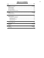
TABLE OF CONTENTS
Page
Safety .......................................................................................................................................i-iv
Installation.......................................................................................................................Section A
Technical Specifications.......................................................................................................A-1
Safety Precautions ...............................................................................................................A-2
General Description..............................................................................................................A-2
Electrical Installation.............................................................................................................A-2
Mechanical Installation.........................................................................................................A-2
Use with hose and suction devices ......................................................................................A-3
Operation.........................................................................................................................Section B
Safety Instructions................................................................................................................B-1
Operating Instructions ..........................................................................................................B-1
Maintenance....................................................................................................................Section C
Safety Precautions...............................................................................................................C-1
Routine and Periodic Maintenance ......................................................................................C-1
Emptying the Particulate Bin.........................................................................................C-1
Replacing the filter ........................................................................................................C-1
Timer for Filter Cleaning ...............................................................................................C-1
Tightening the belts.......................................................................................................C-2
Trouble Shooting............................................................................................................Section D
Trouble Shooting Chart........................................................................................................D-1
Wiring Diagram ...............................................................................................................Section E
Diagram................................................................................................................................E-1
Parts Manual ..................................................................................................................Appendix
Parts Pages.......................................................................................................................P307

X-TRACTOR 4G
A-1
INSTALLATION
A-1
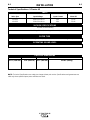
Sales Spec Input Voltage Input Current Motor HP
K1613-1 460V 3 Ph 60 Hz 11A 7.5 HP
K1613-2 230V 3 Ph 60 Hz 23A 7.5 HP
INPUT
HEIGHT WIDTH DEPTH WEIGHT
61.0” (1550 mm) 31.9” (810 mm) 30.7” (780 mm) 396 lbs. (180 kg)
FILTER TYPE
Polyester Cartridge >99% efficiency - 54 ft
2
(5 m
2
) Filter Area - Cleanable using Compressed Air
PHYSICAL DIMENSIONS
Air Flow / Pressure Rating
200 CFM @ 50” WG (340 m
3
/h @ 1270 mm WG)
VACUUM SPECIFICATIONS
OPERATING SOUND LEVEL
<74 dB(A)
Technical Specifications- X-Tractor 4G
NOTE: Technical Specifications are subject to change without prior notice. Specifications and guarantees are
valid only when specified spare parts and filters are used.

A-2
INSTALLATION
X-TRACTOR 4G
A-2
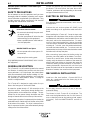
Read this entire installation section before you
start installation.
SAFETY PRECAUTIONS
Do not attempt to use this equipment until you have
thoroughly read all installation, operating and mainte-
nance information supplied with your equipment. They
include important safety precautions and detailed
operating and maintenance instructions.
ELECTRIC SHOCK can kill.
• Do not touch electrically live parts such
as internal wiring.
• Turn the input power off at the fuse box
before working on this equipment.
• Have a qualified person install and ser-
vice this equipment.
------------------------------------------------------------------------
MOVING PARTS can injure.
• Do not operate with covers open or fil-
ter removed.
• Keep away from moving parts.
------------------------------------------------------------------------
Only qualified personnel should install, use or service
this equipment.
GENERAL DESCRIPTION
The X-Tractor 4G is a self contained system for the removal
and filtration of welding fume particles and other point
source particulate. It is a high vacuum, low volume system
which also automatically cleans the filter cartridge. It is suit-
able for heavy duty welding applications and continuous
use, powered by a three phase AC blower. A cooling fan
assists in cooling the blower.
The X-Tractor 4G is designed to supply suction for up to
three or four fume guns or small suction heads.
Air enters the system through a 3" OD connection on the
side of the machine. It then passes through the filter, leav-
ing fume particles on the outside of the cartridge. This par-
ticulate free air then passes through the blower and exits
through an internal silencer and out the top of the machine.
A timer signals a jet-pulse of compressed air that shakes the
particulate from the outside surface of the filter so that it falls
to the bottom of the canister. This air jet is released from a
tank of compressed air that is pressurized externally through
a fitting on the front of the machine.
Vacuum level depends upon the amount of airflow through
the blower. The more airflow, the lower the suction.
Therefore, performance will vary depending on the number
and type of extraction devices in use.
ELECTRICAL INSTALLATION
Only qualified personnel should install, use or service
this equipment.
------------------------------------------------------------------------
Connect the unit to three phase AC (60HZ) input
power according to all applicable codes and stan-
dards.
When installing the X-Tractor 4G - Route the input cable
through the hole at the bottom of the machine, up the inside
wall between the shelf and the sound insulation foam on the
side panel, and into the starter/overload box. For easier
access to the starter/overload box, remove the outside
cover from the box and detach the starter/overload from the
mounting rail. To do this, press the starter/overload down,
and rotate the bottom toward you. To remount, catch the
starter/overload on the top rail and rotate the bottom toward
the bottom rail; it will snap into place.
After connecting input power but before using the
machine, check the rotation of the blower. Turn the X-
Tractor 4G on and off once. As the motor slows down,
visually verify the direction of rotation of the motor fan
with the red arrow sticker on the motor (the motor fan
should be rotating counter-clockwise). If the motor is
rotating backwards, disconnect the unit from input
power and switch two of the input leads to reverse the
direction of rotation; then reconnect the input power.
MECHANICAL INSTALLATION
Install on a flat, level surface. Connect 90 PSI of
clean, dry, compressed air to the foster plug in the
front of the machine.
Do not apply more than 140 psi (10 bar) to the com-
pressed air fitting.
------------------------------------------------------------------------
The blower in the X-Tractor 4G is belt-driven. The
belts must be tightened after the first 100 hours of
use, or when they start to slip (making a loud, squeal-
ing noise). See the MAINTENANCE section for
details.
WARNING
CAUTION
WARNING

A-3
INSTALLATION
X-TRACTOR 4G
A-3
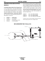
USE WITH HOSE AND SUCTION
DEVICES
A complete package consists of the X-Tractor 4G, one
to four suction devices and the corresponding number
of 1 3/4" (45mm) hoses. All Lincoln suction devices
come with adapters that mate with either 1 3/4" (45mm)
ID Lincoln flexhose (S19947 series) or 1 3/4" (45mm)
OD Lincoln rubber hose (S14927-8). These adapters
connect to the flexhose by “screwing” onto the wire
helix that reinforces the hose. These hoses connect to
the X-Tractor 4G by using the following equipment sup-
plied with the X-Tractor 4G:
2 S22598-14 Rubber Seals
2 S22295 VV-50 Adapters
4 S10888-33 Hose clamps
2 M17321-7 VV-50 distribution valves
4 S20591-8 SR-4550 adapters
The VV-50 valve connects to the 3" (76mm) connec-
tion on the canister by using a S22295 VV adapter
and a S22598-14 rubber seal mounted on the
unvalved connection of the VV-50 valve with two hose
clamps for stability.The second VV-50 valve connects
into the first with another adapter, rubber seal, and
two more hose clamps. Hose connects to the VV-50
valves by using the SR-4550 adapters for the two 2”
(50mm) connections as shown. Recommended hose
for the X-Tractor 4G are:
S19947-9 10 ft., 1 3/4" (45mm) flexhose
S19947-5 16 ft., 1 3/4" (45mm) flexhose
S19947-10 25 ft., 1 3/4" (45mm) flexhose
S14927-8 15 ft., 1 3/4" (45mm) OD rubber hose
Consult Lincoln’s Environmental Systems Division
before using any other size or length of hose.
INCLUDED WITH THE X-Tractor 4G:
HOSE CLAMPS AND RUBBER SEAL
VV ADAPTER
SR-4550
X-TRACTOR 4G
TO 1 3/4 " FLEX HOSE
VV-50 VALVE

B-1
OPERATION
B-1
Read and understand this entire section before oper-
ating your X-Tractor 4G.
SAFETY INSTRUCTIONS
Do not attempt to use this equipment until you have
thoroughly read all operating and maintenance man-
uals supplied with your equipment and any related
welding machine it will be used with. They include
important safety precautions, operating and mainte-
nance instructions and parts lists.
ELECTRIC SHOCK can kill.
•Do not touch electrically live parts such
as output terminals or internal wiring.
•Insulate yourself from the work and
ground.
•Always wear dry insulating gloves.
------------------------------------------------------------------------
WELDING SPARKS can cause fire or
explosion.
•Keep flammable material away.
•Do not weld upon containers which
have held combustibles.
------------------------------------------------------------------------
ARC RAYS can burn.
•Wear eye, ear and body protection.
------------------------------------------------------------------------
FUMES AND GASES
can be dangerous.
• Although the removal of the particu-
late matter from welding smoke may
reduce the ventilation requirement,
concentrations of the clear exhausted
fumes and gases may still be haz-
ardous to health. Avoid breathing
concentrations of these fumes and
gases. Use adequate ventilation
when welding. See ANSI Z49.1,
"Safety in Welding and Cutting", pub-
lished by the American Welding
Society.
------------------------------------------------------------------------
Only qualified personnel should operate this equip-
ment.
ADDITIONAL SAFETY PRECAUTIONS
Always operate this equipment with the filters installed
and covers in place as these provide maximum pro-
tection from moving parts and insure proper vacuum
operation and cooling air flow.
OPERATING INSTRUCTIONS
When a qualified individual has connected the X-Tractor
4G to input power and proper rotation has been verified,
and when the compressed air has been connected, turn
the machine on. The X-Tractor 4G provides enough suc-
tion for up to four fume guns or small suction heads.
A timer triggers the jet-pulse filter cleaning. This time
can be adjusted on timer T1 inside the side door of
the machine. See the MAINTENANCE section.
Disconnect the machine from input power before
opening the side door. Close the door before restor-
ing input power to the machine.
------------------------------------------------------------------------
The blower in the X-Tractor 4G is belt-driven. The
belts must be tightened after the first 100 hours of
use, or when they start to slip (making a loud, squeal-
ing noise). See the MAINTENANCE section for
details.
X-TRACTOR 4G
WARNING
WARNING

C-1
MAINTENANCE
C-1
Before any service or maintenance work is carried
out, the following safety precautions must be
observed.
- Main power supply must be switched off and locked
in the “OFF” position. A warning sign must be put on
the switch to be sure that no one enters the start
cabinet or tries to switch on the power supply.
- Always follow the warning stickers on the unit.
- Do not remove any protective guards before all mov-
ing parts have stopped.
- All service and maintenance must be done by quali-
fied individuals.
- Always use spare parts as described in the Spare
Part List or Lincoln Electric Brown Parts Book.
------------------------------------------------------------------------
ROUTINE MAINTENANCE
Since the X-Tractor 4G is a three-phase, brushless
system with automatic filter cleaning, maintenance is
minimal. Periodic disposal of the particulate should
be the only routine maintenance. The motor and
blower bearings are permanently lubricated.
EMPTYING THE PARTICULATE BIN
The particulate matter collected in the canister may be
dangerous to your health. Take necessary precau-
tions so that you and your fellow workers do not
breathe the dust and particulate. Wear a suitable res-
pirator when disposing of the particulate.
------------------------------------------------------------------------
Check with local authorities for regulations governing
the disposal of this material.
REPLACING THE FILTER
The filter is a long life, polyester filter designed to be
repeatedly cleaned by the X-Tractor’s automatic jet
pulse cycle. Therefore, it should need replacement
only after an extended period of time. Certain applica-
tions can reduce this period, especially those involving
very oily smoke or excessive moisture. Replacement
is necessary when, after several cleaning cycles, the
suction performance of the system is still lower than
normal. Overall filter life depends on a great number
of variables such as type of smoke, duty cycle, operat-
ing factor, capture efficiency, etc.
When replacing the filter, fold down the rubber seals
that seal the canister to the unit. Slide the canister out
of the cabinet. Unlock the canister clamp and lift the
lid. Unscrew the nut under the filter, remove the filter,
install a new filter and replace the nut. Replace the lid
on the canister and clamp down.
The canister should be emptied on a regular basis.
Frequency of emptying depends upon a number of
factors such as the type of welding fume and the fre-
quency of use. In many cases, a good procedure
would be to empty the canister once per month.
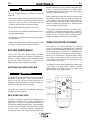
TIMER FOR FILTER CLEANING
(See Figure C.1 for timer illustration) The Cleaning
cycle is controlled by the adjustable timer. Cleaning
frequency can be adjusted by setting the Pause Time
(time between pulses). Pause Time is adjustable from
0.2 to 45 minutes. Pulse Duration can also be adjust-
ed from 0.1 to 30 seconds. The timer is factory preset
at 2 seconds Pulse Duration and 45 minutes Pause
Time. Thus every 45 minutes, the system pulses air
into the filter for 2 seconds.
The system can be manually triggered by pressing the
“Test” button. The green LED is lit when the timer
senses power to its control circuit; the Yellow LED
lights when the timer signals a pulse.
X-TRACTOR 4G
WARNING
WARNING
Figure C.1
10
20
30
0.1
15
30
45
0.2
SEC
A
SUPPLY
ON
LOAD
TEST
MIN
B
X
0.7 A
24/240 V
50/60 HZ
PAUSE TIME
GREEN LED =
(SHOWS POWER TO)
(THE TIMER)
YELLOW LED =
(LIGHTS WHEN PULSE)
(IS SIGNALED)
PULSE DURATION
PUSH-BUTTON
(MANUAL PULSE)

C-2
MAINTENANCE
C-2
X-TRACTOR 4G
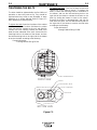
TIGHTENING THE BELTS
The belts should be tightened after the first 100hrs of
operation or when they start to slip. They should be
replaced when they break or are damaged, or when
tightening is no longer effective. Refer to Figure C.2
when tightening or replacing belts.
To tighten the belts:
Open the front door of the cabinet
and remove the dust canister (fold down the rubber
seals that seal the canister to the unit, and slide the
canister out of the cabinet); remove the round cover
plate from the underside of the shelf. Loosen the four
mounting bolts on the bottom of the blower, and use
the belt-tensioning bolt on the right side of the blower
to tension the belts according to the following:
Proper belt tension:
10mm@[email protected]
To replace the belts: Take out the dust canister and
remove the cover plate as above (“To tighten the
belts”). Loosen the mounting bolts on the bottom of
the blower, and use the belt-tensioning bolt on the
right side of the blower to release the tension on the
belts (by sliding the blower in closer to the motor).
Remove the broken or damaged belts, and slip the
new belts into place. Use the belt-tensioning bolt on
the right side of the blower to tension the new belts
according to the following:
Proper belt tension:
10mm@[email protected]
COVER PLATE
PULLEY ON BLOWER
(4) BLOWER MTG. BOLTS
(2) BELTS
FRONT VIEW
BOTTOM VIEW
BELT-TENSIONING BOLT
Figure C.2

D-1
TROUBLESHOOTING
D-1
X-TRACTOR 4G
Observe all Safety Guidelines detailed througout this manual
If for any reason you do not understand the test procedures or are unable to perform the tests/repairs safely, contact your
Local Lincoln Authorized Field Service Facility for technical troubleshooting assistance before you proceed.
CAUTION
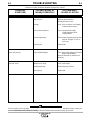
PROBLEMS
PROBLEMS
(SYMPTOMS)
POSSIBLE AREAS OF
MISADJUSTMENTS(S)
RECOMMENDED
COURSE OF ACTION
Poor Suction
Motor not Running
Abnormal noise
Suction device is too far
away from arc
Leakage
Filter not being cleaned
Improper application
Filter blocked
Motor overload tripped
Voltage out of range
Damaged bearings
Belts slipping
Position suction head closer to arc
Optimum capture distance is
generally less than 4 inches.
Check: Hose connections, Hose integrity,
Air path inside the machine.
Check: Compressed air supply
Cleaning frequency timer
Solenoid valves
Check: Number of operators(less than four)
Hose dia. & length.(1
3
/
4
” dia. up
to 50’ long)
Replace filter
Check: proper input voltage on all phases,
proper overload setting
Reset circuit breaker or replace fuse if
necessary
Check: input voltage
Replace bearings or blower
Tighten belts

E-1
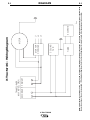
DIAGRAMS
X-TRACTOR 4G
NOTE: This diagram is for reference only. It may not be accurate for all machines covered by this manual. The specific diagram for a particular code is pasted inside
the machine on one of the enclosure panels. If the diagram is illegible, write to the Service Department for a replacement. Give the equipment code number..
PRIMARYSECONDARY
TIMER
OVERLOAD
FAN
MOTOR
SOLENOID
STARTER
L1
L2
L3
COOLING
TRANSFORMER
(460V MODEL ONLY)
C
S22312
X-Tractor 4G - Wiring Diagram
E-1

Now Available...12th Edition
The Procedure Handbook of Arc Welding
With over 500,000 copies of previous editions published
since 1933, the Procedure Handbook is considered by many to
be the “Bible” of the arc welding industry.
This printing will go fast so don’t delay. Place your
order now using the coupon below.
The hardbound book contains over 750 pages of welding
information, techniques and procedures. Much of this material
has never been included in any other book.
A must for all welders, supervisors, engineers and
designers. Many welding instructors will want to use the book
as a reference for all students by taking advantage of the low
quantity discount prices which include shipping by
4th class parcel post.
$15.00 postage paid U.S.A. Mainland
How To Read Shop Drawings
The book contains the latest information and application
data on the American Welding Society Standard Welding
Symbols. Detailed discussion tells how engineers and
draftsmen use the “short-cut” language of symbols to pass
on assembly and welding information to shop personnel.
Practical exercises and examples develop the reader’s
ability
to visualize mechanically drawn objects as they will appear
in their assembled form.
187 pages with more than 100 illustrations. Size 8-1/2” x
11”
Durable, cloth-covered board binding.
$4.50 postage paid U.S.A.
Mainland
New Lessons in Arc Welding
Lessons, simply written, cover manipulatory techniques;
machine and electrode characteristics; related subjects,
such as distortion; and supplemental information on arc
welding applications, speeds and costs. Practice materials,
exercises, questions and answers are suggested for each
lesson.
528 pages, well illustrated, 6” x 9” size, bound in simulated,
gold embossed leather.
$5.00 postage paid U.S.A.
Mainland
Need Welding Training?
The Lincoln Electric Company operates the oldest and
most respected Arc Welding School in the United States at its
corporate
headquarters in Cleveland, Ohio. Over 100,000 stu-
dents have graduated. Tuition is low and the training is
“hands on”
For details write: Lincoln Welding School
22801 St. Clair Ave.
Cleveland, Ohio 44117-1199.
and ask for bulletin ED-80 or call 216-383-2259 and ask
for the
Welding School Registrar.
Lincoln Welding School
BASIC COURSE $700.00
5 weeks of fundamentals
There is a 10% discount on all orders of $50.00 or more for shipment at one time to one location.
Orders of $50 or less before discount or orders outside of North America must be prepaid with charge, check or money order in U.S. Funds Only.
Prices include shipment by 4thClass Book Rate for U.S.A. Mainland Only. Please allow up to 4 weeks for delivery.
UPS Shipping for North America Only. All prepaid orders that request UPS shipment please add:
$5.00 For order value up to $49.99
$10.00 For order value between $50.00 & $99.99
$15.00 For order value between $100.00 & $149.00
For North America invoiced orders over $50.00 & credit card orders, if UPS is requested, it will be invoiced or charged to you at cost.
Outside U.S.A. Mainland order must be prepaid in U.S. Funds. Please add $2.00 per book for surface mail or $15.00 per book for air parcel post shipment.
METHOD OF PAYMENT: (Sorry, No C.O.D. Orders)
CHECK ONE:
Name: _______________________________________________
Please Invoice (only if order is over $50.00)
Address: _______________________________________________
Check or Money Order Enclosed, U.S. Funds only
_______________________________________________
Credit Card - Telephone:_______________________________________________
Signature as it appears on Charge Card:
Account No.
|_|_|_|_|_|_|_|_|_|_|_|_|_|_|_|_|_|_|_|_|_| Exp Date |_|_| |_|_|
______________________
Month Year
USE THIS FORM TO ORDER:
Order from: BOOK DIVISION, The Lincoln Electric Company, 22801 St. Clair Avenue, Cleveland, Ohio 44117-1199
BOOKS OR FREE INFORMATIVE CATALOGS Telephone: 216-383-2211 or, for fastest service, FAX this completed form to: 216-361-5901.
Lincoln Welding School Titles: Price Code Quantity Cost
(ED-80)
New Lessons in Arc Welding $5.00 L
Seminar Information Procedure Handbook “Twelfth Edition” $15.00 PH
(ED-45)
How to Read Shop Drawings $4.50 H
Educational Video Information Incentive Management $5.00 IM
(ED-93)
A New Approach to Industrial Economics $5.00 NA
James F. Lincoln Arc Welding The American Century of John C. Lincoln $5.00 AC
Foundation Book Information Welding Preheat Calculator $3.00 WC-8
(JFLF-515)
Pipe Welding Charts $4.50 ED-89
SUB TOTAL
Additional Shipping Costs if any
TOTAL COST
VISA
®
MasterCardMasterCard
®

WARNING
AVISO DE
PRECAUCION
ATTENTION
WARNUNG
ATENÇÃO
Spanish
French
German
Portuguese
Japanese
Chinese
Korean
Arabic
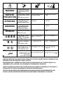
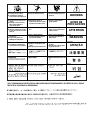
READ AND UNDERSTAND THE MANUFACTURER’S INSTRUCTION FOR THIS EQUIPMENT AND THE CONSUMABLES TO BE
USED AND FOLLOW YOUR EMPLOYER’S SAFETY PRACTICES.
SE RECOMIENDA LEER Y ENTENDER LAS INSTRUCCIONES DEL FABRICANTE PARA EL USO DE ESTE EQUIPO Y LOS
CONSUMIBLES QUE VA A UTILIZAR, SIGA LAS MEDIDAS DE SEGURIDAD DE SU SUPERVISOR.
LISEZ ET COMPRENEZ LES INSTRUCTIONS DU FABRICANT EN CE QUI REGARDE CET EQUIPMENT ET LES PRODUITS A
ETRE EMPLOYES ET SUIVEZ LES PROCEDURES DE SECURITE DE VOTRE EMPLOYEUR.
LESEN SIE UND BEFOLGEN SIE DIE BETRIEBSANLEITUNG DER ANLAGE UND DEN ELEKTRODENEINSATZ DES HER-
STELLERS. DIE UNFALLVERHÜTUNGSVORSCHRIFTEN DES ARBEITGEBERS SIND EBENFALLS ZU BEACHTEN.
● Do not touch electrically live parts or
electrode with skin or wet clothing.
● Insulate yourself from work and
ground.
● No toque las partes o los electrodos
bajo carga con la piel o ropa moja-
da.
● Aislese del trabajo y de la tierra.
● Ne laissez ni la peau ni des vête-
ments mouillés entrer en contact
avec des pièces sous tension.
● Isolez-vous du travail et de la terre.
● Berühren Sie keine stromführenden
Teile oder Elektroden mit Ihrem
Körper oder feuchter Kleidung!
● Isolieren Sie sich von den
Elektroden und dem Erdboden!
● Não toque partes elétricas e elec-
trodos com a pele ou roupa molha-
da.
● Isole-se da peça e terra.
● Keep flammable materials away.
● Mantenga el material combustible
fuera del área de trabajo.
● Gardez à l’écart de tout matériel
inflammable.
● Entfernen Sie brennbarres Material!
● Mantenha inflamáveis bem guarda-
dos.
● Wear eye, ear and body protection.
● Protéjase los ojos, los oídos y el
cuerpo.
● Protégez vos yeux, vos oreilles et
votre corps.
● Tragen Sie Augen-, Ohren- und Kör-
perschutz!
● Use proteção para a vista, ouvido e
corpo.

WARNING
AVISO DE
PRECAUCION
ATTENTION
WARNUNG
ATENÇÃO
Spanish
French
German
Portuguese
Japanese
Chinese
Korean
Arabic
LEIA E COMPREENDA AS INSTRUÇÕES DO FABRICANTE PARA ESTE EQUIPAMENTO E AS PARTES DE USO, E SIGA AS
PRÁTICAS DE SEGURANÇA DO EMPREGADOR.
● Keep your head out of fumes.
● Use ventilation or exhaust to
remove fumes from breathing zone.
● Los humos fuera de la zona de res-
piración.
● Mantenga la cabeza fuera de los
humos. Utilice ventilación o
aspiración para gases.
● Gardez la tête à l’écart des fumées.
● Utilisez un ventilateur ou un aspira-
teur pour ôter les fumées des zones
de travail.
● Vermeiden Sie das Einatmen von
Schweibrauch!
● Sorgen Sie für gute Be- und
Entlüftung des Arbeitsplatzes!
● Mantenha seu rosto da fumaça.
● Use ventilação e exhaustão para
remover fumo da zona respiratória.
● Turn power off before servicing.
● Desconectar el cable de ali-
mentación de poder de la máquina
antes de iniciar cualquier servicio.
● Débranchez le courant avant l’entre-
tien.
● Strom vor Wartungsarbeiten
abschalten! (Netzstrom völlig öff-
nen; Maschine anhalten!)
● Não opere com as tampas removidas.
● Desligue a corrente antes de fazer
serviço.
● Não toque as partes elétricas nuas.
● Do not operate with panel open or
guards off.
● No operar con panel abierto o
guardas quitadas.
● N’opérez pas avec les panneaux
ouverts ou avec les dispositifs de
protection enlevés.
● Anlage nie ohne Schutzgehäuse
oder Innenschutzverkleidung in
Betrieb setzen!
● Mantenha-se afastado das partes
moventes.
● Não opere com os paineis abertos
ou guardas removidas.

• Sales and Service through Subsidiaries and Distributors Worldwide •
Cleveland, Ohio 44117-1199 U.S.A. TEL: 216.481.8100 FAX: 216.486.1751 WEB SITE: www.lincolnelectric.com
World's Leader in Welding and Cutting Products Premier Manufacturer of Industrial Motors
STATEMENT OF LIMITED WARRANTY
The Lincoln Electric Company (Lincoln) warrants to the
end user (purchaser) of all new welding and cutting equip-
ment, electrode and flux (collectively called the “Goods”)
that it will be free of defects in workmanship and material.
This warranty is void if Lincoln or its Authorized Service
Facility finds that the equipment has been subjected to
improper installation, improper care or abnormal opera-
tions.
WARRANTY PERIOD
(1) (2) (3)
Lincoln will assume both the parts and labor expense of
correcting defects during the full warranty period. All war-
ranty periods date from the date of purchase to the original
end user and are as follows:
7 Years
• Main power rectifiers on all non-inverter low frequency
(50 and 60 Hz) type welders.
3 Years
• All Lincoln welding machines, wirefeeders and plasma
cutting machines unless listed below.
2 Years
• Power Arc 5000
Ranger 10, Ranger 10-LX
Weldanpower 125, Weldanpower 150
1 Year
• AC-100
Invertec V100-S, Invertec V130-S, Invertec V200-T
Power Arc 4000
Pro-Cut 20
• All water coolers (internal or external models)
• All stick electrode, welding wire and flux.
• Arc welding and cutting robots and robotic controllers
• All Environmental Systems equipment, including portable
units, central units, gun and cable assemblies and acces-
sories. (Does not include consumable items listed under
30 day warranty.)
• All welding and cutting accessories including gun and
cable assemblies, TIG and plasma torches, spool guns,
wire feed modules, undercarriages, field installed options
that are sold separately, unattached options, welding
supplies, standard accessory sets, replacement parts,
and Magnum products. (Does not include expendable
parts listed under 30 day warranty)
30 Days
• All consumable items that may be used with the environ-
mental systems described above. This includes hoses,
filters, belts and hose adapters.
• Expendable Parts - Lincoln is not responsible for the
replacement of any expendable part that is required due
to normal wear.
CONDITIONS OF WARRANTY
TO OBTAIN WARRANTY COVERAGE:
The purchaser must contact Lincoln or Lincoln’s Authorized
Service Facility about any defect claimed under Lincoln’s
warranty.
Determination of warranty on welding and cutting equip-
ment will be made by Lincoln or Lincoln’s Authorized
Service Facility.
WARRANTY REPAIR:
If Lincoln or Lincoln’s Authorized Service Facility confirms
the existence of a defect covered by this warranty, the
defect will be corrected by repair or replacement at
Lincoln’s option.
At Lincoln’s request, the purchaser must return, to Lincoln
or its Authorized Service Facility, any “Goods” claimed
defective under Lincoln’s warranty.
FREIGHT COSTS:
The purchaser is responsible for shipment to and from the
Lincoln Authorized Service Facility.
WARRANTY LIMITATIONS
Lincoln will not accept responsibility or liability for repairs
made outside of a Lincoln Authorized Service Facility.
Lincoln’s liability under this warranty shall not exceed the
cost of correcting the defect of the Lincoln product.
Lincoln will not be liable for incidental or consequential
damages (such as loss of business, etc.) caused by the
defect or the time involved to correct the defect.
This written warranty is the only express warranty provided
by Lincoln with respect to its products. Warranties implied
by law such as the warranty of merchantability are limited
to the duration of this limited warranty for the equipment
involved.
This warranty gives the purchaser specific legal rights. The
purchaser may also have other rights which vary from state
to state.
(1)
Equipment manufactured for the Lincoln Electric Company is subject to
the warranty period of the original manufacturer.
(2)
All engines and engine accessories are warranted by the engine or
engine accessory manufacturer and are not covered by this warranty.
(3)
SAE400 WELD N’ AIR compressor is warranted by the compressor man-
ufacturer and not covered by this warranty.
LIMITED WARRANTY
Dec, ‘97
-
 1
1
-
 2
2
-
 3
3
-
 4
4
-
 5
5
-
 6
6
-
 7
7
-
 8
8
-
 9
9
-
 10
10
-
 11
11
-
 12
12
-
 13
13
-
 14
14
-
 15
15
-
 16
16
-
 17
17
-
 18
18
-
 19
19


Lincoln Electric X-Tractor 4G Mode d'emploi
- Catégorie
- Système de soudage
- Taper
- Mode d'emploi
dans d''autres langues
Documents connexes
-
Lincoln Electric X-Tractor 3G Mode d'emploi
-
-
-
-
-
-
-
-
-