SYNAPSE EMB-S2-A Controller Guide d'installation
- Taper
- Guide d'installation

21-EMBS2A-INS A-1
SPECIFICATIONS
• Dim Control Max Load: 30 mA Source/Sink
• Radio Frequency: 2.4 GHz (IEEE 802.15.4)
• RF Transmission Output Power: +19dBM
• Operating Temperature: -40 to +80 C
• Operating Humidity: 10 to 90%, non-condensing
• Max D4i Drivers: Limited to a maximum of 6
D4i LED Drivers, any D4i LED Drivers >4 will need
the power supply disabled.
• Wire Size: 20 AWG, 7” Wires, 600V
• Dimensions: 3.05” L x 2.21” W x .47” H
(77.6 x 56.1 x 11.8 mm)
CAUTION
EMB-S2-A controllers must be installed in accordance
with national, state, and local electrical codes and
requirements.
DESIGN CONSIDERATIONS
Below are some recommendations for successful
dimming using the EMB-S2-A. The dimming control
wires are referenced as DIM+ and DALI-/COM. The
dimming signals have a Maximum voltage of 10V DC.
• Do not ground the DALI-/COM wire to chassis
ground; this is a return signal and is critical for
proper dimming.
• Route dimming wires away from AC lines if
possible.
• Maximum of 4 DALI-2/D4i LED Drivers per
controller for DALI-2/D4i Designs.
• Maximum 0f 8 DIM to OFF LED Drivers for DIM to
OFF Designs.
• Do not mount to a heatsink or to a LED driver.
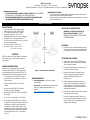
• When installing the EMB-S2-A into an enclosure,
consideration of the external antenna position and
interference is required in order to provide the
most optimum wireless signal strength. Prior to
permanently mounting it, make sure the antenna
points directly upward or downward and is free of
any metal objects within 12 in. of the antenna
(Figure 1).
Figure 1 - Proper Antenna Installation
NEEDED MATERIALS
• Mounting Hardware: (2) #4 and M3 screws
recommended
• Antenna Kit: For available antenna options please
refer to our latest documents located on our
website.
www.synapsewireless.com/documentation
INSTALLATION INSTRUCTIONS
WARNING: TO AVOID FIRE, SHOCK, OR
DEATH: TURN OFF POWER AT CIRCUIT
BREAKER OR FUSE AND VERIFY THAT POWER IS
OFF BEFORE WIRING!
MOUNTING
1. Place the controller in desired location and secure
it using #4 or M3 sized screws using the mounting
holes located on the back edge of the EMB-S2-A.
ATTACHING THE ANTENNA
2. Make sure the power is off. When handling the
antenna cable, the technician must be grounded
with a proper ground strap.
3. Remove red rubber dust cover, the washer, and
nut from the antenna connector.
4. Determine best location for external antenna
position and create an opening to mount the
antenna and bulkhead (See Figure 2 for
measurements).
5. Feed the bulkhead through the opening in the
fixture. (Note: Recommended max thickness of
fixture wall is 6mm or 0.25 inches. This allows
enough threads on the outside of the fixture for a
good antenna connection.)
6. Place the washer and the nut back on the antenna
connector and secure to fixture.
7. Screw on the antenna hand tight. Tighten a 1/4
turn with a pair of needle nose pliers. Do not over
tighten or the RF pin in the bulkhead will crack,
creating poor RF link quality.
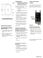
EMB-S2-A Controller
Load Ratings: 12 to 24VDC, +/-10%, 700mW max
Operating Temperature: -40 to +80 C / Operating Humidity: 10 to 90%, non-condensing
WARNING AND CAUTIONS:
•TO AVOID FIRE, SHOCK, OR DEATH: TURN OFF POWER AT CIRCUIT BREAKER
OR FUSE AND TEST THAT POWER IS OFF BEFORE INSTALLING!
•PROPER GROUNDING REQUIRED TO AVOID STATIC DISCHARGE WHICH
CAN DAMAGE CONTROLLERS DURING INSTALLATION.
INSTALLATION GUIDE
WARNING AND CAUTIONS:
•If you are unsure about any part of these instructions, consult an electrician; all
work should be performed by qualified personnel.
•Disconnect power at circuit breaker or fuse when servicing, installing or removing
fixture or changing lamps.

21-EMBS2A-INS A-1
Figure 2 – Recommended mounting hole for
1/4-36UNS-2A threaded antenna with flat
WIRING THE EMB-S2-A CONTROLLER
Note: Unless specified, the connections to a
standard Dim to Off LED driver and the DALI 2
LED driver are the same.
8. Connect the 12-24VDC Aux output from the LED
driver to the (POWER = BROWN wire of the
EMB-S2-A.
9. Connect the (DALI-/COMMON = PINK/WHITE
STRIPE) wire of the EMB-S2-A to the
COMMON/DALI- or COMMON/DIM- based on the
LED driver you have.
CONNECTING SENSORS
• Note: Steps 10-14 are for adding sensors
to the EMB-S2-A controller; if you are not
connecting sensors skip this section.
There are two sensor inputs on the EMB-S2-A designed
for low powered (24V DC) type sensors.
• The (SENSOR A = YELLOW) wire is used to
connect sensor A.
• The (SENSOR B = ORANGE) wire is used to
connect sensor B.
10. Connect the sensor power wire to the AUX out on
the LED driver (the LED driver powers the sensor).
11. Connect the sensor DALI-/COMMON to the
COMMON/DALI- or COMMON/DIM- based on the
LED driver you have.
12. Connect the sensor CTRL/Control wire to the
(SENSOR A = YELLOW) wire or the (SENSOR B =
ORANGE) wire of the EMB-S2-A controller.
13. If you are using more than one sensor then
duplicate the installation as described above.
14. Sensors must be configured in software before
they are functional in a SimplySnap system.
(See Figures 3 AND 4)
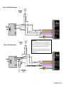
CONNECTING THE DIMMING CIRCUIT
Note: Steps 15-17 are for connecting up to a
Standard Dim to Off LED driver; if you are using a
DALI 2 LED driver skip to steps 18-20.
15. Connect the (DIM+ = PURPLE) wire from the EMB-
S2-A to the DIM+ wire on the LED driver.
16. Connect the (DALI-/COMMON = PINK/WHITE
STRIPE) wire from the EMB-S2-A to the DIM- wire
on the LED driver.
17. Cap unused (DALI+ = PURPLE/WHITE STRIPE)
wires.
(See Figure 3)
Note: Steps 18-20 are for connecting up to a
DALI 2 LED driver.
18. Connect the EMB-S2-A (DALI-/COMMON =
PINK/WHITE STRIPE) to the COMMON/DALI- wire
on the LED driver.
19. Connect the (DALI+ = PURPLE/WHITE STRIPE)
wire from the EMB-S2-A to the LED driver DALI+.
20. Cap the unused (DIM+ = PURPLE) wire.
(See Figure 4)
POWERING UP THE FIXTURE AND
CONTROLLER
After connecting the Controller to the LED Driver and
any sensors, make sure to cap any unused wires.
Switch power on to the fixture. The light should turn
on.
STATUS LED
Note: When the controller is powered the
following colors indicate the current status.
• Red = No Network Found (Communication Lost)
• Blinking Green = Network Found, Controller Not
Configured (Device not yet added to SimplySnap)
• Green = Network Found, Controller Configured
(Normal Operation)
Refer to the SimplySnap User’s Manual for information
on provisioning the EMB-S2-A.
STATUS LED

21-EMBS2A-INS A-1
Figure 3 - DIM to OFF Wiring Diagram
Figure 4 - DALI-2 Wiring Diagram
WARNING:
· If a single Synapse controller is used to drive the DIM+
input of multiple LED drivers, then all of the DIM- lines
from all drivers MUST be directly tied/shorted together to
provide a common return/ground to the controller.
· Synapse will not warranty or be liable for designs with
any other electronic means of coupling DIM- lines from
multiple drivers.

21-EMBS2A-INS A-1
REGULATORY INFORMATION AND
CERTIFICATIONS
RF Exposure Statement: This equipment complies
with FCC radiation exposure limits set forth for an
uncontrolled environment. This equipment should be
installed and operated with minimum distance of 20cm
between the radiator and your body. This transmitter
must not be co-located or operating in conjunction with
any other antenna or transmitter.
Industry Canada (IC) certifications: This digital
apparatus does not exceed the Class B limits for radio
noise emissions from digital apparatus set out in the
Radio Interference Regulations of the Canadian
Department of Communications.
Le present appareil numerique n’emet pas de bruits
radioelectriques depassant les limites applicable aux
appareils numeriques de la class B prescrites dans le
Reglement sur le brouillage radioelectrique edicte par
le ministere des Communications du Canada.
FCC certifications and regulatory information
(USA only)
FCC Part 15 Class B: This device complies with part
15 of the FCC rules. Operation is subject to the
following two conditions: (1) These devices may not
cause harmful interference, and (2) These devices
must accept any interference received, including
interference that may cause harmful operation.
RADIO FREQUENCY INTERFERENCE (RFI) (FCC
15.105): This equipment has been tested and found to
comply with the limits for a Class B digital device,
pursuant to Part 15 of the FCC rules. These limits are
designed to provide reasonable protection against
harmful interference in a residential installation. This
equipment generates, uses, and can radiate radio
frequency energy and, if not installed and used in
accordance with the instructions, may cause harmful
interference to radio communications. However, there
is no guarantee that interference will not occur in a
particular installation. If this equipment does cause
harmful interference to radio or television reception,
which can be determined by turning the equipment off
and on, the user is encouraged to try to correct the
interference by one or more of the following measures:
(1) Re-orient or relocate the receiving antenna; (2)
Increase the separation between the equipment and
the receiver; (3) Connect the equipment into an outlet
on a circuit different from that to which the receiver is
connected; (4) Consult the dealer or an experienced
radio/TV technician for help.
Declaration of Conformity (FCC 96-208 & 95-19):
Synapse Wireless, Inc. declares that the product name
“EMB-S2-A” to which this declaration relates, meet the
requirements specified by the Federal Communications
Commission as detailed in the following specifications:
• Part 15, Subpart B, for Class B equipment
• FCC 96-208 as it applies to Class B personal
computers and peripherals
• This product has been tested at an External Test
Laboratory certified per FCC rules and has been found
to meet the FCC, Part 15, Emission Limits.
Documentation is on file and available from Synapse
Wireless, Inc.
If the FCC ID for the module inside this product
enclosure is not visible when installed inside another
device, then the outside of the device into which this
product is installed must also display a label referring
to the enclosed module FCC ID. Modifications (FCC
15.21): Changes or modifications to this equipment not
expressly approved by Synapse Wireless, Inc., may
void the user’s authority to operate this equipment.
CERTIFICATIONS
Model : EMB-S2-A
Contains FCC ID : U9O-SM520
Contains IC : 7084A-SM520
UL File No : E346690
DALI-2 Certified Application Controller
Contact Synapse for Support- (877) 982-7888
Patented – virtual marking at
https://www.synapsewireless.com/about/patents
-
 1
1
-
 2
2
-
 3
3
-
 4
4


