Hobart CLeN Dishwasher Manuel utilisateur
- Taper
- Manuel utilisateur

– 1 –
E
E
701 S. RIDGE AVENUE
TROY, OHIO 45374-0001
937 332-3000
www.hobartcorp.com F47607 (November 2021)
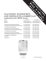
CLeN-SERIES DISHWASHERS
LAVE-VAISSELLE DE LA GAMME CLeN
LAVAVAJILLAS SERIE CLeN
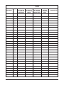
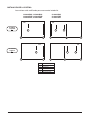
MODEL R-L OPERATION L-R OPERATION
MODÈLE EXPLOITATION D A G EXPLOITATION G A D
MODELO FUNCIONAMIENTO D-I FUNCIONAMIENTO I-D
CL44eN-BAS/CL44eN-EGR/CL44eN-ADV ML-138401-0000Z ML-138402-0000Z
CLPS66eN-BAS/CLPS66eN-EGR/CLPS66eN-ADV ML-138403-0000Z ML-138404-0000Z
CLCS66eN-BAS/CLCS66eN-EGR ML-138409-0000Z ML-138410-0000Z
CL54eN-BAS/CL54eN-EGR/CL54eN-ADV ML-138405-0000Z ML-138406-0000Z
CLPS76eN-BAS/CLPS76eN-EGR/CLPS76eN-ADV ML-138407-0000Z ML-138408-0000Z
CLCS76eN-BAS/CLCS76eN-EGR ML-138411-0000Z ML-138412-0000Z
CL64eN-BAS/CL64eN-EGR/CL64eN-ADV ML-138413-0000Z ML-138414-0000Z
CLPS86eN-BAS/CLPS86eN-EGR/CLPS86eN-ADV ML-138415-0000Z ML-138416-0000Z
CLCS86eN-BAS/CLCS86eN-EGR ML-138417-0000Z ML-138418-0000Z
CL44eN-VL ML-138470-0000Z ML-138471-0000Z
CLPS66eN-VL ML-138472-0000Z ML-138473-0000Z

– 2 –
IMPORTANT FOR YOUR SAFETY
THIS MANUAL HAS BEEN PREPARED FOR PERSONNEL QUALIFIED
TO INSTALL GAS EQUIPMENT, WHO SHOULD PERFORM THE INITIAL
FIELD START-UP AND ADJUSTMENTS OF THE EQUIPMENT COVERED
BY THIS MANUAL.
POST IN A PROMINENT LOCATION THE INSTRUCTIONS TO BE
FOLLOWED IN THE EVENT THE SMELL OF GAS IS DETECTED. THIS
INFORMATION CAN BE OBTAINED FROM THE LOCAL GAS SUPPLIER.
IMPORTANT
IN THE EVENT A GAS ODOR IS DETECTED, SHUT DOWN UNITS
AT MAIN SHUTOFF VALVE AND CONTACT THE LOCAL GAS
COMPANY OR GAS SUPPLIER FOR SERVICE.
FOR YOUR SAFETY
DO NOT STORE OR USE GASOLINE OR OTHER FLAMMABLE
VAPORS OR LIQUIDS IN THE VICINITY OF THIS OR ANY OTHER
APPLIANCE.
FOR YOUR SAFETY
READ BEFORE OPERATING
DO NOT USE THIS APPLIANCE IF ANY PART HAS BEEN
UNDER WATER. IMMEDIATELY CALL A QUALIFIED SERVICE
TECHNICIAN TO INSPECT THE APPLIANCE AND TO REPLACE
ANY PART OF THE CONTROL SYSTEM AND ANY GAS
CONTROL WHICH HAS BEEN UNDER WATER.
IN THE EVENT OF A POWER FAILURE, DO NOT ATTEMPT TO
OPERATE THIS DEVICE.
© HOBART CORPORATION, 2021

– 3 –
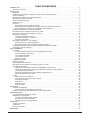
TABLE OF CONTENTS
GENERAL .....................................................................................4
Chemical Sanitizing. . . . . . . . . . . . . . . . . . . . . . . . . . . . . . . . . . . . . . . . . . . . . . . . . . . . . . . . . . . . . . . . . . . . . . . . . . . 5
INSTALLATION .................................................................................5
Unpacking ..................................................................................5
Ventless Heat Pump Assembly Installation .........................................................5
Installation Codes ............................................................................5
Adjust Machine Height and Level Machine .........................................................5
Dish Table Assembly ..........................................................................5
Splash Shields ..............................................................................6
Water Requirements ..........................................................................7
Plumbing Connections ........................................................................7
Drain Connection .........................................................................7
Drain Water Tempering Kit (If Equipped) .......................................................8
Water Connections .......................................................................8
Chemical Feeder Installations ...................................................................9
Detergent Feeder .........................................................................9
Rinse Agent Feeder .......................................................................9
Chemical Sanitizer Feeder. . . . . . . . . . . . . . . . . . . . . . . . . . . . . . . . . . . . . . . . . . . . . . . . . . . . . . . . . . . . . . . . . . 9
Steam Connection (When Equipped for Steam Heat) ...............................................10
Gas Connection (When Equipped for Gas Heat) ...................................................10
Venting Requirements .......................................................................11
Type II Canopy Hood ....................................................................11
Pant-Leg Vent Connections ................................................................12
Exhaust Flow Requirements ...............................................................14
Electrical Connections – Dishwasher ............................................................14
Motor Rotation – Three-Phase Only .........................................................16
Optional Equipment Control Connections .....................................................16
CLeN-EGR and CLeN-ADV Energy Recovery Set-Up ...............................................17
DelimeNoticationSetup .....................................................................19
OPERATION ..................................................................................20
Preparation ................................................................................20
If Equipped with Scrapper (PS/CS) ..........................................................20
Wash/Rinse Tanks .......................................................................20
CLeN-ADV Models. . . . . . . . . . . . . . . . . . . . . . . . . . . . . . . . . . . . . . . . . . . . . . . . . . . . . . . . . . . . . . . . . . . . . . . 21
CLeN-VL Models ........................................................................21
Curtains & Doors ........................................................................21
Curtain Installation ..........................................................................22
Keypad and Display .........................................................................25
Filling the Dishwasher ........................................................................25
Starting the Gas Heat Dishwasher (When Equipped with Gas Heat) ....................................25
Minimum Temperatures .......................................................................25
Minimum Temperatures Using High-Temperature Sanitizing .......................................26
Minimum Temperatures Using Low-Temperature, Chemical Sanitizing ...............................26
Alternative Temperature Display Names ......................................................26
Low FR Temp Alert .......................................................................26
Tank Temperature Alert ...................................................................26
Dishwashing ...............................................................................27
Pot and Pan Mode .......................................................................28
Optional Table Limit Switch ................................................................28
Auto-Timer .............................................................................28
Idle Mode ..............................................................................28
Energy Saver Mode ......................................................................28
Dirty Water Mode ........................................................................28
CLEANING ....................................................................................29
Deliming Procedure. . . . . . . . . . . . . . . . . . . . . . . . . . . . . . . . . . . . . . . . . . . . . . . . . . . . . . . . . . . . . . . . . . . . . . . . . . 31
Clearing the DelimeRecommendedNotication ................................................32
DOs and DON'Ts for Your New Hobart Warewasher ................................................32
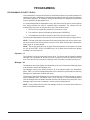
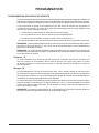
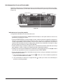
PROGRAMMING ...............................................................................33
Programming Security Levels ..................................................................33
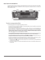
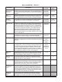
Programming Instructions .....................................................................34
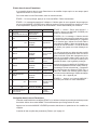
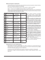
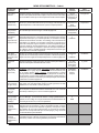
Menu Display Prompts ....................................................................34
Entering the Parameters Menu .............................................................35
Navigating the Parameters Menu ...........................................................35
MAINTENANCE ................................................................................37
Vent ......................................................................................37
Lubrication. . . . . . . . . . . . . . . . . . . . . . . . . . . . . . . . . . . . . . . . . . . . . . . . . . . . . . . . . . . . . . . . . . . . . . . . . . . . . . . . . 37
Service ...................................................................................37
TROUBLESHOOTING ...........................................................................38

– 4 –
Installation, Operation and Care Of
CLeN-SERIES DISHWASHERS
SAVE THESE INSTRUCTIONS
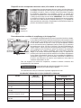
GENERAL
CLeN machines are rack-type warewashers that move the racks from one end of the machine to the
other,exposingthewaretoprogressivewashandrinsezones.Pumpsandnalrinseareactivated
bytheinsertedracktoenergizethespecicwashorrinseactionneeded.TheCLeN-series machines
are offered in optional lengths, sections, features, and provide different speeds to meet productivity
and performance requirements. All CLeN-Series Dishwashers have electronic controls with digital
temperature displays.
The CLeN-EGR models have a drain water energy recovery system which includes drain water
tempering and all of the standard features of the CLeN. They use a heat exchanger to capture the
energyfromthedrainwaterandpreheatincomingcoldwaterforthenalrinse.TheCLeN-EGR
units are only available in hot water sanitizing mode, three phase, and come standard with a built-in
30kWboosterheater,whichisdesignedtomaintainnalrinsetemperatureof180°Fwithaminimum
incomingcoldwatertemperatureof55°F.
The CLeN-ADV models have an Automatic Soil Removal (ASR) system and include all of the
standard features of the CLeN-EGR. The ASR system automatically redirects food soil left over
after pre-scrapping to an external scrap basket located at the load end of the machine. This helps
to keep the wash water cleaner, reducing the frequency of water changes. This saves the customer
money on chemicals and water/energy. The CLeN-ADV-Series machines are only available in hot
water sanitizing mode, electric heat, three phase voltage supply, and come standard with a 30KW
built-in booster heater. The CLeN-ADV models are not available with a corner scrapper unit (CLCS).
The CLeN-VL models have a ventless system and include all the standard features of the CLeN
Basemodels.The ventlesssystemuses energyefcientheat-pumptechnology combined with
energy recovery to remove the need for direct venting while providing auxiliary heat to the wash
tank. The CLeN-VL machines require only a single cold-water supply and are only available in hot
water sanitizing mode, electric heat, three phase voltage supply, and come standard with a 30KW
built-in booster heater.
Tanks, chambers, frames, legs and adjustable feet are made of welded stainless steel construction.
Hinged inspection doors provide access to the interior wash and rinse zones. CLPS models provide
a 22-inch power scrapper section and hinged access door. The power scrapper removes the heavy
soil before the rack enters the wash zone.
Machines can be ordered as left-to-right or right-to-left operation. Either electric, gas, or steam tank
heatisspeciedattimeoforder.Machinescomestandardreadytooperatewithhigh-temperature
sanitizing mode.
Hobart offers three right-angle possibilities to put your machine in a corner installation (not available
on CLeN-VL models):
• The Side Loader moves the rack at a right angle into the machine from the scrapping area.
• The Direct Drive Unloader moves the rack at a right angle coming out of the machine to tabling
where the clean ware can be unracked.
• The Corner Scrapper (CLCS models) puts a Power Scrapper in the corner location at the load
end of your machine, combining right angle entry with a scrapper section.

– 5 –
CHEMICAL SANITIZING
CLeN machines can be converted to operate with low-temperature sanitizing mode (with
the use of chemical sanitizers). Refer to Sanitation Mode programming instructions on
page 36. NOTE: Chemical sanitization is not available on the CLeN-EGR, CLeN-ADV, or
CLeN-VLmodels.
Hot water sanitizing mode is designated by "High Temp." on the display when the machine
is turned on. Low-temperature or chemical sanitizing mode is designated by "Low Temp."
on the display when the machine is turned on.
CLeNmodelsthatoperatewithchemicalsanitization,useincomingwaterandnalrinse
waterat120°Fminimum.Tankheatersraisethattemperatureto130°Fforwash(andpower
rinse, if equipped).
INSTALLATION
UNPACKING
Immediately after unpacking the dishwasher, check for possible shipping damage. If the
machine is found to be damaged, save the packaging material and contact the carrier within
5 days of delivery.
NOTE: For CLeN-VL models, ventless heat pump assembly ships separate on its own skid.
Priortoinstallation,verifythattheelectricalserviceagreeswiththespecicationsonthe
machine data plate, which is located on the left-hand side of the control box.
Afterunpackingthedishwasher,removetheitemsshippedloose(overowtubeorstandpipe,
splash shields, curtains, extra wash arm caps, and literature envelope with instructions and
chamber hole plug kit) from inside the dishwasher. For CLeN-ADV models only, remove the
external ASR basket from inside the dishwasher and install in the ASR housing located at
the load end of the machine.
VENTLESS HEAT PUMP ASSEMBLY INSTALLATION
Refer to Hobart Service CLeN Ventless Installation manual, F-45820.
INSTALLATION CODES
Installation must be in accordance with state and local codes, or in the absence of local
codes, with the National Fuel Gas Code, ANSI Z223.1 (latest edition), if applicable, and the
National Electrical Code ANSI/NFPA 70 (latest edition). In Canada, the installation standards
are: CAN/CSA B149.1 and CSA C22.1 (latest editions).
ADJUST MACHINE HEIGHT AND LEVEL MACHINE
Set the dishwasher in its proper location. Adjust the height and level the machine by turning
the adjustable feet in or out as necessary.
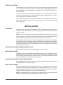
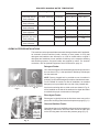
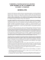
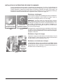
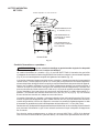
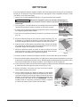
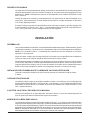
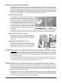
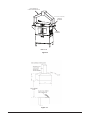
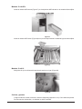
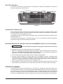
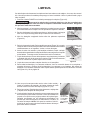
DISH TABLE ASSEMBLY
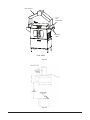
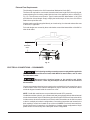
Dishtablesshouldbettedintothedishwasher(Figs.1,2&3).Usesiliconesealantbetween
table and lip of tank to prevent leakage. Rack track height should be from 1/4 to 5/16" (Fig. 2)
above the tank lip. Dish tables should be sloped so that any water carried from the dishwasher
will drain back into the machine, but not from the scrapping area.
NOTE: Thedishwashermustbeinitsnalposition,adjustedforproperheightandproperly
leveled before table assembly and plumbing connections are made.

– 6 –
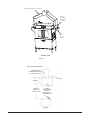
Fig. 1
Fig. 2 Fig. 3
For CLeN-VL installations, the extended hoods can be adjusted to accomodate variances
in dish tables by loosening the three screws.
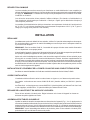
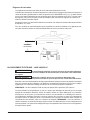
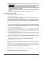
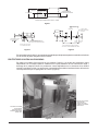
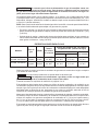
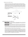
SPLASH SHIELDS
On all CLeN models (except CLeN-VL models), two splash shields are shipped with machine
for installation on the front side of the load and unload ends of the machine. Mount splash
shields to chamber ends using hardware provided. Splash shields should be installed inside
tablerimtopreventwaterfromdrippingontooor(Fig.4).
SPLASH SHIELD
(INSTALLED INSIDE
ROLLED RIM)
SPLASH SHIELD
(INSTALLED INSIDE
ROLLED RIM)
Fig. 4

– 7 –
WATER REQUIREMENTS
Proper water quality can improve ware washing performance by reducing spotting, enhancing
effectiveness of labor and extending equipment life. Water conditions vary from one location
toanother.Therecommendedproperwatertreatmentforeffectiveandefcientuseofthis
equipment will also vary depending on the local water conditions. Ask your municipal water
supplierfordetailsaboutlocalwaterspecicspriortoinstallation.
Recommended water hardness is 3 grains of hardness per gallon or less. Chlorides must not
exceed 30 parts per million. Water hardness above 3 grains per gallon should be treated by
a water conditioner (water softener or in-line treatment). Water treatment has been shown
to reduce costs associated with machine cleaning, reduce deliming of the dishwasher and
reduce detergent usage in the dishwasher.
NOTE: For CLeN-VL models, damage to heat pump system due to improper water quality
may not be covered under Hobart warranty.
Sediment,silica,chloridesorotherdissolvedsolidsmayrequireparticulateltrationorother
water treatment.
If an inspection of the dishwasher or booster heater reveals lime buildup after the equipment
has been in service, in-line water treatment is recommended. Contact your local Hobart
Serviceofceforspecicrecommendations.
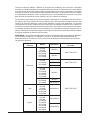
PLUMBING CONNECTIONS
Plumbing connections must comply with applicable sanitary, safety
and plumbing codes.
The plumber who connects this machine is responsible for making certain that both water
and steam lines are THOROUGHLY FLUSHED OUT BEFORE connecting to any manual
valve or solenoid valve.
This‘‘ush-out’’isnecessarytoremoveallforeignmatter,suchaschips(resultingfrom
cuttingorthreadingofpipes),pipejointcompoundfromthelinesor,ifsolderedttingsare
used, bits of solder or cuttings from the tubing. Debris, if not removed, may lodge in the
valves and render them inoperative. Manual valves or solenoid valves found defective by
foreign matter and any expenses resulting from this debris are NOT the responsibility of
the manufacturer.
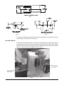
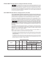
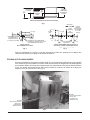
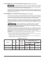
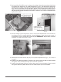
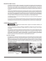
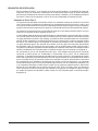
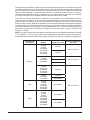
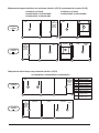
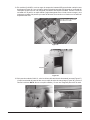
Drain Connection
Thecommondrainforthetank(s)requiresonlyoneconnectiontotheoordrain.Thedrain
can be connected at either end. A pipe plug is provided for the opposite end. NOTE: For
CLeN-EGR and CLeN-ADV models, the factory drain plumbing may need to be relocated to
opposite side of drain body (Fig. 5). Connect the drain (Fig. 6) through a trap to the sewer
using2"NPTpipe.Ifagreasetrapisrequiredbycode,itshouldhaveaminimumow
capacity of 38 gallons per minute.

– 8 –
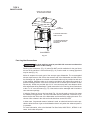
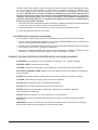
Drain Water Tempering Kit (If Equipped)
A drain water tempering kit is factory installed on all CLeN-EGR and
CLeN-ADV models and is available as an accessory for all CLeN-BAS
and CLeN-VL models. Refer to F-45654 CLeN Drain Water Tempering
Kit Installation Instructions supplied with the kit for proper installation.
NOTE: For CLeN-EGR and CLeN-ADV models, the DWT thermostat
is mounted to the frame behind the front panel (Fig. 7). The thermostat
capilliary must be routed and installed in the drain line at the factory
connection point.
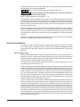
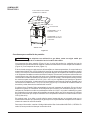
Water Connections
CLeN-BAS models require a single incoming hot water supply. CLeN-
EGR and CLeN-ADV models require a hot and a cold water supply.
CLeN-VL models require a single cold-water supply. Use 1/2" minimum
I.D. pipe size for the incoming water supply line(s) to the machine
(Fig.8).Aowingpressureof15to25psigmustbemaintainedat
the machine. For long runs, use larger pipe and insulation to ensure
adequate pressure and temperature. On CLeN-BAS models without
built-inboosterheater,ifowpressureexceeds25psig,apressure-
reducing valve (by others) must be installed in the water supply line
prior to booster heater. On CLeN-BAS models with built-in booster
heater and all CLeN-EGR, CLeN-ADV, and CLeN-VL models, pressure
reducing valves are factory installed in the water supply lines.
For temperature requirements, refer to the Required Incoming Water Temperature
table below.
The water pressure regulator must have a relief bypass. Failure to use
the proper type of pressure regulator may result in damage to the machine.
Apressuregaugeisprovidedforvericationofproperwaterpressure.
Fig. 8
STRAINER
CLEANOUT INCOMING WATER
DRAIN CONNECTION
AT EITHER END
Fig. 5 Fig. 6
CLeN-EGR & CLeN-ADV
DRAIN PLUMBING
DRAIN WATER
TEMPERING KIT
THERMOSTAT
Fig. 7

– 9 –
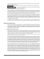
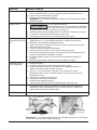
CHEMICAL FEEDER INSTALLATIONS
This machine must be operated with an automatic detergent feeder and, if applicable,
an automatic chemical sanitizer feeder, including a visual means to verify that
detergents and sanitizers are delivered or a visual or audible alarm to signal if
detergents and sanitizers are not available for delivery to the respective washing
and sanitizing systems. Chemical feeders are supplied by others. For electrical
connection, refer to Optional Equipment Control Connections, page 16.
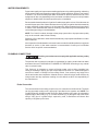
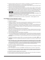
Detergent Feeder
Your chemical supplier will install a detergent feeder port similar to
the one shown in Fig. 9, that provides for discharge of detergent
into the wash tank.
NOTE: Factory plugged hole is provided at rear of machine in
tank wall. Do not install detergent port above chamber/tank seam.
For CLPS66eN-VL models, for ease of installation, an extended
detergent port is provided at the rear side of the prewash tank.
An electric monitoring device, similar to the one shown in Fig. 10,
will be installed on the side of the wash tank to signal the feeder
to maintain the proper concentration of detergent.
Rinse Agent Feeder
Rinseagentistypicallyfedintothenalrinsewateratoneofthe
ports on the incoming water line below the pressure gauge (Fig. 11).
Chemical Sanitizer Feeder
Chemical sanitizer (on CLeN-BAS machines using low-temperature
sanitizing)isfedintothenalrinsewaterlineattheotherport
on the incoming water line below the pressure gauge (Fig.11).
RINSE AID
AND / OR
CHEMICAL
SANITIZER
FEED PORTS
Fig. 11
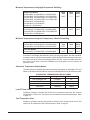
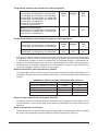
REQUIRED INCOMING WATER TEMPERATURE
Model Sanitizing Mode Connection Water Supply
Minimum Maximum
CLeN-BAS without
Built-in Booster
Hot Water Sanitizing Hot Water 180°F (82°C) 194°F (82°C)
CLeN-BAS without
Built-in Booster
Chemical Sanitizing Hot Water 120°F (49°C) N/A
CLeN-BAS with 15kW
Built-in Booster
Hot Water Sanitizing Hot Water 140°F (60°C) N/A
CLeN-BAS with 30kW
Built-in Booster
Hot Water Sanitizing Hot Water 110°F (43°C) N/A
CLeN-EGR and
CLeN-ADV with 30kW
Built-in Booster
Hot Water Sanitizing Cold Water 55°F (13°C) 80°F (27°C)
Hot Water 110°F (43°C) N/A
CLeN-VL with 30kW
Built-in Booster
Hot Water Sanitizing Cold Water 55°F (13°C) 80°F (27°C)
Fig. 9 Fig. 10

– 10 –
STEAM CONNECTION (When Machine is Equipped with Steam Tank Heat)
Steam supply pressure must agree with the steam trap (supplied) which is rated
for 10 to 50 psig differential pressure. Ifowingpressureexceeds50psig,apressureregulator
(by others) must be installed in the supply line. Steamowiscontrolledbysolenoidvalves.
For single-tank steam coil installations, two connections are required, one for supply and
one for return. For two-tank steam coil installations, one common supply connection and
two return connections are required.
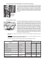
GAS CONNECTION (When Machine is Equipped with Gas Tank Heat)
Check the gas data plate attached to the dishwasher on the side of the control box or refer
to the tag attached to the gas burner tubing for the type of gas to be used. All machines are
shippedconguredfornaturalgas.IfconversiontoLPgas(propane)isrequired,aconversion
kit with instructions is supplied and must be installed before the machine is operated.
Theburnerisnotadjustable.Ifowinggaspressureisabove7"W.C.(naturalgas)or11"W.C.
(propane gas), an additional regulator valve (by others) must be installed in the supply line.
Static incoming line pressure should not exceed 14.0" W.C. for either propane or natural gas.
The gas supply line to the dishwasher must be provided with a shut-
off valve per code. The appliance and its gas connections must be leak tested before
placing the appliance in operation. Use soapy water for leak tests. DO NOT use an
open ame.
The installation must conform with local codes, or in the absence of local codes, with the
National Fuel Gas Code, ANSI Z223.1 (latest edition), available from the American Gas
Association, Inc., 1515 Wilson Blvd., Arlington, VA 22209. In Canada, comply with CAN/
CSA B149.1 and CSA C22.1 (latest editions).
NOTE: For gas line pipe connections, use Loctite 565, Hobart part number 546292, or a
exiblesealantsuitableforusewithNaturalandPropaneGases.
• The appliance and its individual shutoff valve must be disconnected from the gas supply
piping system during any pressure testing of that system at test pressures in excess of
1/2 psig (3.45 kPa).
• The appliance must be isolated from the gas supply piping system by closing its individual
manual shutoff valve during any pressure testing of the gas supply piping system at test
pressures equal to or less than 1/2 psig (3.45 kPa).
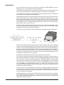
GAS SPECIFICATIONS
Models Type of
Gas BTU/Hr Connection
Line Size
Flowing Gas Pressure - Not Static
Inches W.C. (Water Column)
Incoming Line Pressure Manifold
Pressure
Minimum Maximum
CL44eN, CLPS66eN
CL54eN, CLPS76eN
Natural
Propane
78,000
78,000
1/2" NPT
1/2" NPT
3.5" W.C.
9.0" W.C.
7.0" W.C.
11.0" W.C.
3.2" W.C.
8.2" W.C.
CL64eN, CLPS86eN Natural
Propane
156,000
156,000
3/4" NPT
3/4" NPT
3.5" W.C.
9.0" W.C.
7.0" W.C.
11.0" W.C.
3.2" W.C.
8.2" W.C.

– 11 –
Dissipate test pressure from the gas supply line before reconnecting the appliance and its
manual shutoff valve to the gas supply line.
Failure to follow this procedure may damage the gas valve.
Gas heat machines must be provided with a means to exhaust the
ue gases to the exterior of the building.
Refer to Venting Requirements on pages 11 – 14.
Thedishwashermustbeinstalledsothattheowofcombustionandventilationairwillnot
beobstructed.Ensurethatnoelectricalcablesorplumbingareroutedoverthegasue
area. Adequate clearances for air openings into the combustion chamber must be provided.
Make sure there is an adequate supply of make-up air in the room to allow for combustion
of the gas at the burner(s).
Keep the appliance area free and clear from all combustible substances. Do not obstruct
theowofcombustionandventilationair.Thedishwashermusthaveaminimumclearance
from combustible construction of 3" at the rear and 0" at the sides. A clearance of 23" must
be provided at the front and 20" at each end of the dishwasher for servicing and proper
operation.
The burner is ignited automatically by solid-state electronic circuitry. There is no pilot light.
Gasowisregulatedbythetemperaturecontrolcircuit.
VENTING REQUIREMENTS
For CLeN-VL models, no pant leg duct or canopy hood venting is required. Ensure dish
room HVAC system is adequately sized to handle dish machine heat dissipation (latent
and sensible heat). No HVAC supply or return grills to be installed within 24” of heat pump
assembly.
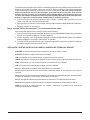
Type II Canopy Hood
Most commercial dishwashers must be provided with external venting per local codes. The
exception is electric or steam heat machines operating in the chemical or low temperature
sanitizing mode where the existing room ventilation will compensate for the vapors produced.
Thelocalauthorityhasnaljurisdictionoverthismatter.
Venting can be provided by either a canopy hood over the whole machine (Fig. 12) or by
the pant-leg duct connection (Fig. 13).
A Hobart CLeN-Seriesdishwasherequippedforgastankheatisnotprovidedwithauecollar
andisnotintendedtohavetheuedirectlyconnectedtoaventilationsystem.However,the
products of combustion must be vented to the outside air. Exhaust air must not be vented into
a wall, a ceiling, or a concealed space of a building. A vent hood over the entire dishwasher
(Fig. 12) can be employed to vent both the moist air from the dishwashing chamber and
theuegasesfromthegasheater.Thevolumeofueexhaustrequiredforventingmoist
airanduegasesusingasingleventhoodovertheentiredishwashermustbecalculated
using the Exhaust Flow Requirements on page 14.
A Type II canopy hood is recommended. A factory-built commercial exhaust hood may be
listed as conforming to Underwriters Laboratory's Standard 710 titled, Exhaust Hoods for
Commercial Cooking Equipment. Hoods must be installed according to the manufacturer's
instructions.Makeupairmustbeprovidedsothattheexhaustowrateresultsinapositive
building pressure in the room where the unit is located (more outside air than exhaust air).
Factory-built hoods not tested to UL Standard 710 and custom built hoods must comply with
thefollowingspecications:Theymustbebuiltfromstainlesssteel,0.022"[No.24Gage]
minimum thickness, or copper sheet weighing at least 24 ounces per square foot; the hood
must be secured in place by noncombustible supports and the hood must meet the Exhaust
Flow Requirements on page 14.

– 12 –
Pant-Leg Vent Connections
Gas heat machines must be provided with a means to exhaust the
ue gases to the exterior of the building.
Pant-Leg duct connectors (Fig. 13) alone DO NOTprovideventilationforthegasueat
the rear of the machine. A mini-vent hood (Fig. 14) must be used or a canopy type hood
may be used (Fig. 12).
Moist air escapes from each end of the conveyor type dishwasher. The recommended
exhaust requirement is 200 CFM at the entrance end of the dishwasher and 400 CFM at
the discharge end. Optional vent hoods or extended hoods may be provided at each end
ofthemachine.Sufcientmake-upairmustbeprovidedsotheexhaustowresultsina
positive building pressure in the room in which the unit is located (more outside air than
exhaust air). Hoods are provided with 4" x 16" vent connectors with vent dampers which
allow adjustment during installation. Typical construction is for 'Pant-Leg' hood connections
tothe4"x16"ventconnectors(Fig.13).Ventstacksmustbewatertightandtinsidethe
vent connector openings.
Ifusingthe'Pant-Leg'duct,amini-venthood(Fig.14)mustbeusedtoventtheuegases
on machines using gas heat. The mini-vent hood must be positioned a minimum of 18"
abovetheueexitattherearofthedishwasherandconnectedtoexistingductwork.The
volumeofueexhaustinthemini-venthoodshouldnotexceed200CFM.
In either case, if a powered means of exhaust is used, an electrical interlock must be pro-
videdtoallowtheowofgastothedishwasherburneronlywhentheexhaustsystemis
in operation.
For more information, refer to the National Fuel Gas Code, ANSI Z223.1, NFPA54. In all
cases, local codes will prevail.
Fig. 12
TYPE II
CANOPY HOOD
EXHAUST DUCT SHOULD
BE CENTERED IN HOOD
1' TO 4'
CLEARANCE
6" MINIMUM OVERHANG
FRONT & BACK
18" MINIMUM OVERHANG
AT LOAD AND UNLOAD
OPENINGS
CLeN SERIES

– 13 –
PANT-LEG DUCT
4” x 16”
VENT
CONNECTOR
EXTENDED
HOOD
CLeN-SERIES
Fig. 13
Fig. 14

– 14 –
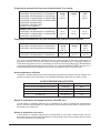
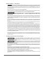
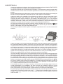
Exhaust Flow Requirements
The following is based on the 2015 International Mechanical Code (IMC):
Theow of air required for a vent hood is based on the linear length of the face of the hood,
measured along the front side, parallel with the front of the appliance (refer to LENGTH in
Fig.15).TheminimumnetairowforTypeIIhoodsusedwithdishwashersis100 CFM
per linear foot of hood length. Simply multiply the hood's length, in feet, times 100 CFM to
obtaintherequiredowrate.
Subtractmake-upairowsupplieddirectlytoahoodcavity,fromthetotalexhaustowrate
of the hood, if applicable.
For hood designs not covered by these calculations consult the latest edition of the IMC or
other local codes.
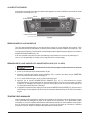
ELECTRICAL CONNECTIONS — DISHWASHER
Electrical and grounding connections must comply with the applicable
portions of the National Electrical Code, ANSI / NFPA 70, latest edition, and / or other
local electrical codes.
Disconnect the electrical power to the machine and follow
lockout / tagout procedures. There may be multiple circuits. Be sure all circuits are
disconnected.
Connect a permanent electrical power supply to the terminal block in the control box on top
of the machine. Refer to the machine data plate for proper connection information and the
electrical diagram located inside the control box cover.
NOTE: CLeN dish machines are not provided with internal GFCI protection.
CLeN dish machines (electric, gas or steam tank heat) not equipped with the Hobart internal
electric booster heater, ship from the factory wired for a Single Point Electric Connection which
includesmotors&controlsandtankheat.Electrictankheatmodelscanbeeldconverted
todualormultiplepointelectriccongurations.Conversioninstructionsarelocatedinthe
dishmachine’scontrolboxlocatedontopoftheunit.NOTE: For electric heat machines,
SinglePointElectricConnectionisonlyavailableon3-phasevoltagecongurations.Single
phaseelectricheatunitsshipwithadualpointelectricconguration.
CLEARANCE
HEIGHT
LENGTH
Fig. 15

– 15 –
All 480/60/3, 380/60/3 (except for electric heat two-tank models) and 600/60/3 machines
equipped with the Hobart internal electric booster heater ship from the factory wired for a
Single Point Electric Connection which includes motors & controls, electric tank heat (if
equipped)andtheelectricboosterheater.Theunitcanbeeldconvertedtodualormultiple
pointelectriccongurations.Conversioninstructionsarelocatedinthedishmachine’scontrol
box located on top of the unit.
For all other voltages on CLeN dish machines equipped with the Hobart internal electric
boosterheater,theunitwillshipfromthefactoryconguredfordualelectricconnections;eld
installed Single Point Electric Connection kits are available. The kits include all necessary
wires,fuses,terminalblocksandwiringinstructionstocongurethemachineforaSingle
Point Electric Connection which includes motors & controls, electric tank heat (if equipped)
and the electric booster heater. Refer to the chart below to determine which single point kit
is required based on model, tank heat type and voltage.
NOTE:SinglePointElectricConnectionisnotavailableasastandardcongurationon
CL44eN-VL, CLPS66eN-VL,CL64Tandothervariousspecialdevicecongurations.Contact
HobartSalesforspecicquestionsregardingspecialcongurations.
Tank Heat Model Volts / Hz / Ph Sales Accessory Kit
Electric
CL44eN
CL54eN
CLPS66eN
CLCS66eN
CLPS76eN
CLCS76eN
200/50/3
SGLPT-KIT4-CLE
208/60/3
CL64eN
CLPS86eN
CLCS86eN
200/50/3
SGLPT-KIT3-CLE
208/60/3
240/60/3
CL44eN
CL54eN
CLPS66eN
CLCS66eN
CLPS76eN
CLCS76eN
240/60/3
SGLPT-KIT2-CLE
CL64eN
CLPS86eN
CLCS86eN
380/60/3
380-415/50/3
Gas
CL44eN
CL54eN
CL64eN
CLPS66eN
CLPS76eN
CLPS86eN
208-240/60/3
Steam
CL44eN
CL54eN
CL64eN
CLPS66eN
CLCS66eN
CLPS76eN
CLCS76eN
CLPS86eN
CLCS86eN
200-240/50/3
208-240/60/3

– 16 –
Motor Rotation — Three-Phase Only
Before placing a three-phase machine into service, check to verify that the
conveyor motor rotates in the correct direction. (The control box is pre-wired at the factory
so that all motors are phased together. If the conveyor motor rotation is correct, the pump
motors will also be correct.) Incorrect rotation will result in unacceptable performance.
To check the conveyor motor's rotation:
Closethemachinedoors,pressPOWERonthekeypadandallowthemachinetoll.When
themachineiscompletelylled,pressPOWERtoturnthemachineoff.
Disconnect the electrical power to the machine and follow
lockout / tagout procedures. There may be multiple circuits. Be sure all circuits are
disconnected.
Remove the front panel below the doors. Reconnect the electrical power to the machine,
being careful not to touch any uninsulated electrical parts exposed by removing the front
panel. Press START/ENTER on the keypad and verify proper motor rotation, as follows:
The conveyor motor and clutch must rotate counterclockwise for machines with right-to-left
operation, and clockwise for machines with left-to-right operation.
If the rotation of the conveyor motor is correct, press POWER to turn the machine off.
Disconnect electrical power to the machine, and replace the front panel.
If the conveyor motor does not rotate in the proper direction, disconnect the electrical power
to the machine. At the machine control box on top of the machine, reverse any two of the
incoming power supply leads, either the leads to the entire machine, or the leads to the
motor and controls if they are wired independent of the heaters. Do not simply reverse the
leads to the conveyor motor.
Reconnect the electrical power to the machine. Re-check the conveyor motor's rotation.
The conveyor motor and clutch must rotate counterclockwise for machines with right-to-left
operation, and clockwise for machines with left-to-right operation.
If the rotation of the conveyor motor is correct, press POWER to turn the machine off.
Disconnect the electrical power to the machine. Replace the top cover to the control box,
and replace the front panel.
Optional Equipment Control Connections
Electrical and grounding connections must comply with the applicable
portions of the National Electrical Code, NFPA 70 (latest edition) and/or other local
electrical codes.
Disconnect the electrical power to the machine and follow lockout/
tagout procedures. There may be multiple circuits. Be sure all circuits are disconnected.
Detergent Feeder
The maximum rating for a detergent dispenser connected to DPS1 and DPS2 is
1.5 amps at line voltage. Refer to Chemical Feeder Installations, page 9.
Rinse Aid Feeder and/or Chemical Sanitizer Feeder
The maximum rating for a rinse aid dispenser and/or chemical sanitizer feeder connected to
RPS1 and RPS2 is 1.5 amps at line voltage. Refer to Chemical Feeder Installations, page 9.

– 17 –
Vent Fan Control (Not Available on CLeN-VL models)
The maximum rating for a vent fan connected to VFC1 and VFC2 is 1HP @ 120VAC, 2.5HP
@ 240VAC.
The vent fan control circuit will turn the roof exhaust fan on and off with the power on the
dish machine, eliminating the need for a separate switch on the wall. When this circuit is
utilized, the exhaust fan on the roof will turn on when the power button on the CLeN dish
machine is pressed turning the dish machine on and the fan will turn off when the power
button is pressed turning the dish machine off.
The dish machine does not supply any voltage thru this circuit. It is a controlling circuit utilizing
a dry contact. A hot wire from the roof fan control connects to one of the VFC terminals
located on the 5TB terminal block in the CLeN control box on top of the unit and a second
wire connects to the second VFC terminal and wires to the roof fan control completing the
circuit. The dish machine will then open and close this circuit as it is powered on and off,
which will turn the roof exhaust fan on and off with the dish machine.
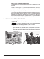
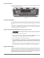
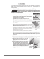
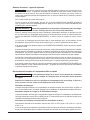
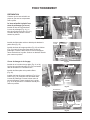
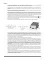
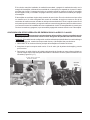
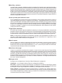
CLeN-EGR AND CLeN-ADV ENERGY RECOVERY SETUP
Disconnect the electrical power to the machine and follow lockout/
tagout procedures. There may be multiple circuits. Be sure all circuits are disconnected.
Set up procedures must be performed after hot and cold water connections
have been completed, tank(s) are full, and machine is ready for operation.
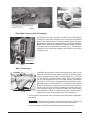
1. Turn main power to machine OFF at customers disconnect.
2. Ensure tank(s) are empty. If not empty, pull drain lever(s) and allow tank(s) to drain.
3. Disconnectoneelectricalleadathotllsolenoidvalvecoillocatedatthetoprearof
unit by sliding the coil cover off and disconnecting one of the coil wires (Figs. 16 & 17).
Fig. 16
SLIDE OFF COVER
Fig. 17
REMOVE
COIL WIRE

– 18 –
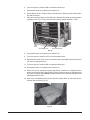
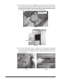
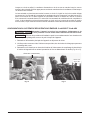
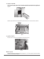
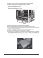
Fig. 18
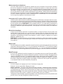
4. Turn main power to machine ON at customers disconnect.
5. Press power button on keypad to turn machine on.
6. Ensuredisplayshows“Tank(s)Filling”andthatwaterisowingintothemachinethru
thenalrinsearms.
7. Whilethemachineisllingthruthenalrinse,adjustthenalrinsehotwaterpressure
regulatingvalve(Fig.18)untilthenalrinsepressuregaugereads20±5PSI.
8. Press power button on keypad to turn machine off.
9. Turn main power to machine OFF at customers disconnect.
10.Reconnectthehotllvalvecoilwireremovedinstep3andreplacethesolenoidvalve
coil cover by sliding it back on.
11. Turn main power to machine ON at customers disconnect.
12. Press power button on keypad to turn machine on.
13.Ensurellcycleisoperatingcorrectlyandallowthemachinetocompletelyllthe
tank(s) and enter the Idle mode (“Tank(s) Filling” should no longer be displayed once
theunitiscompletelylled).NOTE: Duringthisllprocess,thepressuregaugeshould
read approximately 5 PSI.
14.Opendoorofdishwasherandinsertadishrackupsidedowninnalrinsezoneto
activatenalrinseow(Fig.19).
COLD WATER PRVHOT WATER PRV
Fig. 19

– 19 –
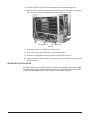
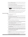
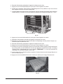
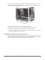
15.PresstheSTARTkeylocatedonthekeypadandensurethenalrinseison.
16.Whilenalrinsewaterisrunning,adjustthenalrinsecoldwaterpressureregulating
valve(Fig.20)untilthenalrinsepressuregaugereads20±5PSI.
17. Press power button on keypad to turn machine off.
18. Turn main power to machine OFF at customers disconnect.
19.Opendoorofdishwasherandremovedishrackfromnalrinsezone.
20. Turn main power to machine ON at customers disconnect; machine is now ready for
normal operation.
DELIME NOTIFICATION SETUP
All CLeN models have the ability to notify the operator when to delime based on the water
hardnessoftheincomingwatersupplytothemachineandthenalrinsewaterusage.Refer
tothe‘PROGRAMMING’sectionofthismanualtosetthewaterhardness.
Fig. 20
COLD WATER PRVHOT WATER PRV

– 20 –
OPERATION
PREPARATION
Make sure the dishwasher is clean and all parts are in place.
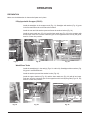
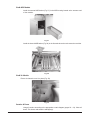
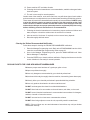
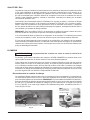
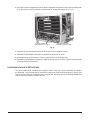
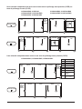
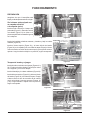
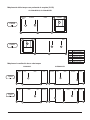
If Equipped with Scrapper (PS/CS)
Install the standpipe in the scrapper tank (Fig. 21). Standpipe with strainer (Fig. 21) goes
inthersttankwheretherackentersthemachine.
Install the rear and side strainer pans and lower the strainer bucket (Fig. 23).
Install the upper wash arm (Fig. 22) and the lower wash arm (Fig. 23) in the scrapper with
all end caps. Push arm onto the connector pipe so the opposite end is held by the guide;
then lift or lower into position.
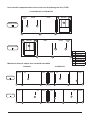
Wash/Rinse Tanks
Install the standpipe(s) in the tank(s) (Figs. 21 and/or 24). Standpipe without strainer (Fig.
24) goes in second/third tank.
Install the strainer pan and the strainer bucket (Fig. 26).
Install the upper wash arm (Fig. 25) and the lower wash arm (Fig. 26) with all end caps.
Push arm onto the connector pipe so the opposite end is held by the guide (Figs. 25, 26);
then lift or lower into position.
Fig. 26
STRAINER
PAN
STRAINER
BUCKET
WASH ARM
GUIDE
CONNECTOR PIPE
END CAPS
Fig. 21 Fig. 22
END CAPS
PREWASH ARM
CONNECTOR PIPE
GUIDE
LATCH
Fig. 23
STRAINER
PANS
CONNECTOR
PIPE
STRAINER
BUCKET
PREWASH ARM
GUIDE
STANDPIPE
STRAINER
CONNECTOR
PIPE
WASH ARM
GUIDE
LATCH
END
CAPS
Fig. 24 Fig. 25
La page est en cours de chargement...
La page est en cours de chargement...
La page est en cours de chargement...
La page est en cours de chargement...
La page est en cours de chargement...
La page est en cours de chargement...
La page est en cours de chargement...
La page est en cours de chargement...
La page est en cours de chargement...
La page est en cours de chargement...
La page est en cours de chargement...
La page est en cours de chargement...
La page est en cours de chargement...
La page est en cours de chargement...
La page est en cours de chargement...
La page est en cours de chargement...
La page est en cours de chargement...
La page est en cours de chargement...
La page est en cours de chargement...
La page est en cours de chargement...
La page est en cours de chargement...
La page est en cours de chargement...
La page est en cours de chargement...
La page est en cours de chargement...
La page est en cours de chargement...
La page est en cours de chargement...
La page est en cours de chargement...
La page est en cours de chargement...
La page est en cours de chargement...
La page est en cours de chargement...
La page est en cours de chargement...
La page est en cours de chargement...
La page est en cours de chargement...
La page est en cours de chargement...
La page est en cours de chargement...
La page est en cours de chargement...
La page est en cours de chargement...
La page est en cours de chargement...
La page est en cours de chargement...
La page est en cours de chargement...
La page est en cours de chargement...
La page est en cours de chargement...
La page est en cours de chargement...
La page est en cours de chargement...
La page est en cours de chargement...
La page est en cours de chargement...
La page est en cours de chargement...
La page est en cours de chargement...
La page est en cours de chargement...
La page est en cours de chargement...
La page est en cours de chargement...
La page est en cours de chargement...
La page est en cours de chargement...
La page est en cours de chargement...
La page est en cours de chargement...
La page est en cours de chargement...
La page est en cours de chargement...
La page est en cours de chargement...
La page est en cours de chargement...
La page est en cours de chargement...
La page est en cours de chargement...
La page est en cours de chargement...
La page est en cours de chargement...
La page est en cours de chargement...
La page est en cours de chargement...
La page est en cours de chargement...
La page est en cours de chargement...
La page est en cours de chargement...
La page est en cours de chargement...
La page est en cours de chargement...
La page est en cours de chargement...
La page est en cours de chargement...
La page est en cours de chargement...
La page est en cours de chargement...
La page est en cours de chargement...
La page est en cours de chargement...
La page est en cours de chargement...
La page est en cours de chargement...
La page est en cours de chargement...
La page est en cours de chargement...
La page est en cours de chargement...
La page est en cours de chargement...
La page est en cours de chargement...
La page est en cours de chargement...
La page est en cours de chargement...
La page est en cours de chargement...
La page est en cours de chargement...
La page est en cours de chargement...
La page est en cours de chargement...
La page est en cours de chargement...
La page est en cours de chargement...
La page est en cours de chargement...
La page est en cours de chargement...
La page est en cours de chargement...
La page est en cours de chargement...
La page est en cours de chargement...
La page est en cours de chargement...
La page est en cours de chargement...
La page est en cours de chargement...
La page est en cours de chargement...
La page est en cours de chargement...
La page est en cours de chargement...
La page est en cours de chargement...
La page est en cours de chargement...
La page est en cours de chargement...
La page est en cours de chargement...
La page est en cours de chargement...
La page est en cours de chargement...
-
 1
1
-
 2
2
-
 3
3
-
 4
4
-
 5
5
-
 6
6
-
 7
7
-
 8
8
-
 9
9
-
 10
10
-
 11
11
-
 12
12
-
 13
13
-
 14
14
-
 15
15
-
 16
16
-
 17
17
-
 18
18
-
 19
19
-
 20
20
-
 21
21
-
 22
22
-
 23
23
-
 24
24
-
 25
25
-
 26
26
-
 27
27
-
 28
28
-
 29
29
-
 30
30
-
 31
31
-
 32
32
-
 33
33
-
 34
34
-
 35
35
-
 36
36
-
 37
37
-
 38
38
-
 39
39
-
 40
40
-
 41
41
-
 42
42
-
 43
43
-
 44
44
-
 45
45
-
 46
46
-
 47
47
-
 48
48
-
 49
49
-
 50
50
-
 51
51
-
 52
52
-
 53
53
-
 54
54
-
 55
55
-
 56
56
-
 57
57
-
 58
58
-
 59
59
-
 60
60
-
 61
61
-
 62
62
-
 63
63
-
 64
64
-
 65
65
-
 66
66
-
 67
67
-
 68
68
-
 69
69
-
 70
70
-
 71
71
-
 72
72
-
 73
73
-
 74
74
-
 75
75
-
 76
76
-
 77
77
-
 78
78
-
 79
79
-
 80
80
-
 81
81
-
 82
82
-
 83
83
-
 84
84
-
 85
85
-
 86
86
-
 87
87
-
 88
88
-
 89
89
-
 90
90
-
 91
91
-
 92
92
-
 93
93
-
 94
94
-
 95
95
-
 96
96
-
 97
97
-
 98
98
-
 99
99
-
 100
100
-
 101
101
-
 102
102
-
 103
103
-
 104
104
-
 105
105
-
 106
106
-
 107
107
-
 108
108
-
 109
109
-
 110
110
-
 111
111
-
 112
112
-
 113
113
-
 114
114
-
 115
115
-
 116
116
-
 117
117
-
 118
118
-
 119
119
-
 120
120
-
 121
121
-
 122
122
-
 123
123
-
 124
124
-
 125
125
-
 126
126
-
 127
127
-
 128
128


Hobart CLeN Dishwasher Manuel utilisateur
- Taper
- Manuel utilisateur
dans d''autres langues
- English: Hobart CLeN Dishwasher User manual
- español: Hobart CLeN Dishwasher Manual de usuario

