
AP1 & RP SERIES
PROF
GE AL
HOOD STYLE Page 1
To register this
product visit:
www.broan.com
FOR DOMESTIC
WAR.I.G
TO REDUCE THE RISK OF FIRE, ELECTRIC SHOCK, OR IN-
JURY TO PERSONS, OBSERVE THE FOLLOWING:
1. Use this unit only in the manner intended by the manufac-
turer. If you have questions, contact the manufacturer at the
address or telephone number listed in the warranty.
2. Before servicing or cleaning unit, switch power off at service
panel. Lock or tag service panel to prevent power from being
switched on accidentally.
3. Installation work and electrical wiring (including switch loca-
tion) must be done by a qualified person(s) in accordance
with all applicable codes and standards, including fire-rated
construction.
4. Provide sufficient air for proper combustion and exhausting
of gases through the flue (chimney) dfuel burning equip-
ment to prevent backdrafting. Follow the combustion equip-
ment standards such as those published by the National
Fire Protection Association (NFPA), the American Society
for Heating, Refrigeration and Air Conditioning Engineers
(ASHRAE), and local codes.
5. This product may have sharp edges. Be careful to avoid cuts
and abrasions during installation and cleaning.
6. When cutting or drilling into walt or ceiling, do not damage
electrical wiring and other hidden utilities.
7. Ducted fans must always be vented to the outdoors.
8. Use only metal ductwork.
9. As an alternative, this product may be installed with the UL-
approved cord kit designated for the product, following in-
structions packed with the cord kit.
10. This unit must be grounded.
TO REDUCE THE RISK OF A RANGE TOP GREASE FIRE:
1. Never leave surface units unattended at high settings.
Boitovers cause smoking and greasy spitlovers that may ig-
nite. Heat oils slowly on low or medium settings.
2. Always turn hood ON when cooking at high heat or when
flambeing food (i.e. Crepes Suzette, Cherries Jubilee, Pep-
percorn Beef Ftambe).
3. Clean ventilating fans frequently. Grease should not be al-
lowed to accumulate on fan or filter.
4. Use proper pan size. Always use cookware appropriate for
the size of the surface element.
COOKING ONLY
TO REDUCE THE RISK OF INJURY TO PERSONS iN THE
EVENT OF A RANGE TOP GREASE FIRE, OBSERVE THE
FOLLOWING:*
1. SMOTHER FLAMES with a close-fitting lid, cookie sheet,
or metal tray, then turn off the burner. BE CAREFUL TO
PREVENT BURNS. If the flames do not go out immediately,
EVACUATE AND CALL THE FIRE DEPARTMENT.
2. NEVER PICK UPA FLAMING PAN --You may be burned or
spread the fire.
3. DO NOT USE WATER, including wet dishcloths or towels
- violent steam explosion will result.
4. Use an extinguisher ONLY if:
A. You know you have a Class ABC extinguisher and you
already know how to operate it.
B. The fire is small and contained in the area where it started.
C. The fire department is being called.
D. You can fight the fire with your back to an exit.
* Based on "Kitchen Fire Safety Tips" published by NFPA.
CAUTION
1. For general ventilating use only. Do not use to exhaust haz-
ardous or explosive materials and vapors.
2. For best capture of cooking impurities, range hood should be
mounted so that the bottom of the hood is 18"-24" above the
cooking surface.
3. Read specification label on product for information and re-
quirements.
_These instructions are for ducted installations only.
If hood is to be installed non-ducted:
Purchase a non-ducted filter kit from your local distributor or
retailer. (Available forAP1 & RP2 Series hoods only.) Follow
instructions included with the non-ducted kit.
Homeowner: Installer: Leavethis manualwith the homeowner.
Cleaning, MaintenanceandOperating instructions on page2.

AP1 & RP SERIES
Page 2
CLEANING & MAINTENANCE
For performance, appearance, and health reasons, clean filter,
fan and grease-laden surfaces. Use only a clean cloth and mild
detergent solution on stainless and painted surfaces. Clean all-
metal filters in the dishwasher.
The motor is permanently lubricated and never needs oiling. If
the motor bearings make excessive or unusual noise, replace
the motor with the exact service motor. The impeller should also
be replaced.
Use 120 V, 50 W, shielded halogen bulbs - MR16 or PAR16 with
GUI0 base. Purchase bulbs separately.
The grease filters, bottom panel, and blower wheel should be
cleaned frequently. Use a warm detergent solution. The grease
filters and blower wheel are dishwasher safe.
Note: Some minerals, when in contact with dishwasher
soap additives, may cause filters to discolor. This discol-
oration is not covered by the warranty.
AP SERIES HOOD
Operate the hood as follows:
© •
®
e
o
FAN
0
LIGHT
FAN
The 2-position switch (in center) turns blower ON and OFF.
The 5-position switch (at left) controls blower speed.
O Blower is OFF (secondary blower OFF).
• Blower is ON at highest speed.
• ® • As dots get smaller - blower speed decreases.
O
OPERATION
Always turn the hood ON before cooking in order to establish an
air flow in the kitchen. After turning off the range, let the hood run
for a few minutes to clear the air.
HEAT SENTRY TM
The hood is equipped with a Heat Sentry TM thermostat. This safety
device wilt turn on or speed up the blower if it senses excess heat
above the cooking surface.
If the blower is not on, or if it is running at tow speed, the Heat
Senttry TM will override the normal blower control and trun the
blower on the high speed. When the temperature level drops to
normal levels, the blower will return to its original setting.
RP SERIES HOOD
Operate the hood as follows:
J
_ BLOWER SWITCH
This 3-position switch turns blower ON and OFF and controls
blower speed.
Set switch to (1) position to turn blower ON to tow speed.
Set switch to (2) position to turn blower ON to high speed.
Set switch to (0) position to turn blower OFF.
"_ LIGHT SWITCH
This 3-position switch turns lights ON and OFF and controls
their intensity.
Set switch to (1) position to turn lights ON to tow intensity.
Set switch to (2) position to turn lights ON to high intensity.
Set switch to (0) position to turn lights OFF.
LIGHT
This 3-position switch (at right) turns lights ON and OFF and
controls their intensity.
O Lights are OFF.
(_ Lights are ON to low intensity.
Lights are ON to highest intensity.
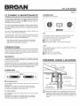
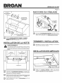
PREPARE HOOD LOCATION
ROOF CAP 3%"X 10"
(For vertical
SOFFIT
HOUSE WIRING
or Back of hood)
WALL CAP
A 3¼" X 10" DUCT
|(For horizontal discharge
18" - 24" ABOVE
COOKING SURFACE
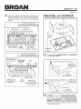
E3Determine whether hood will discharge vertically or hori-
zontally. For vertical or horizontal discharge, run ductwork
between the hood location and a roof cap or wall cap. For
best results, use a minimum number of transitions and
elbows.

AP1 & RP SERIES
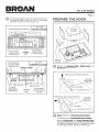
[_ Use the diagram below, for placement of ductwork
proper
and electrical cutout in cabinet or wall. For a non-ducted
installation, DO NOT cut a duct access hole.
31/4"X 10"
HOOD MOUNTING SCREWS (4) VERTICAL DUCTING
121¼'' (30" hood) /121¼" (30" hood) ====_
_J=== 1" . 1 n .
15_ (36 hood)_15_ (36 hood)
F CAB! l
| 6 /8" BOTTOM _=====7 2"=-_ / I "
/ _,.--_'_/9÷,8,, /
105,8,,I vERT,oA,ooo_I11 IJ_! 9"
t ELECTRICAL
WOOD SHIMS ACCESS HOLE
(recessed-bottom CENTER
cabinets only) LINE (in cabinet bottom)
WOOD SHIMS
(recessed-bottom
cabinets only)
,====_
I
/
\\
MOUNTING
l3¼" X I0"HORIZONTAL DUCTING
SCREWS (4)
CABINET FRONT 3/4"
lJ8"1 J Ii
_--- ! L !
'T 'i °
3718,, HORIZONTAL DUCT I T
CABINETJL ACCESS HOLE J
I._,,,==61,,/4_== 61,,/4'L==_
BOTTOM
12¼" (30" hood) _. 71/2"
,== ,, _ 12¼ (30"hood)
15¼" (36 hood) Ii5Y:" <36" hood)
HOOD _,
CENTER
LINE
ELECTRICAL
ACCESS HOLE
(in wall)
Page 3
PREPARE THE HOOD
WIRING
COVER
I
= i ! =
AL_UMINUM I
FILTERS '
Remove the Aluminum Filters. Bottom and
Cover,
Wirinq Cover from the hood.
fVERTICAL DISCHARGE POSITION
-- BLOWER
_.__ /"-_----?".. _ MOUNTING
_'_':', I _<_ ROD <2)
HORIZONTAL DISCHARGE POSITION
-,-IT BLOWER
i _i i -- _ _ _ I _ MOUNTING
[!1 Blower is shipped in Vertical Dischar_cLe_Position.
To change blower to Horizontal Dischar_cLe_Position:
Remove Knurled Nuts from Blower Mountin_ Rods.
Disengage mounting rods from blower and rotate blower
to horizontal discharge position. Re-engage mounting
rods and tighten blower in place with knurted nuts.

AP1 & RP SERIES
Page 4
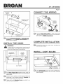
DAMPER /
DUCT
CONNECTOR
VERTICALDUCT
KNOCKOUT
/
i11 i/I
HORIZONTAL DUCT
•"KNOCKOUT
CONNECT THE WIRING
HOUSE
POWER
CABLE
GREEN
GROUND
SCREW
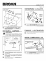
[_ Connect House Power Cable to hood wiring
range
- BLACK to BLACK, WHITE to WHITE, and GREEN or
BARE WIRE to GREEN Ground Screw.
3 Remove Vertical Duct Knockout or Horizontal Duct
Knockout and attach Damper /Duct Connector with
two (2) screws (supplied).
INSTALL THE HOOD
_ ARNING
To reduce the risk of electrical shock, switch power off
at service panel. Lock or tag service panel to prevent
power from being switched on accidentally.
COMPLETE INSTALLATION
Re-install the wiring cover, bottom cover, and filters that
were removed in Step 3.
m
MOUNTING
SCREWS (4)
J
<t>
I
© HOUSE
POWER
CABLE
o!
,, //.,d
DUCTWORK
m
m
Run House Power Cable between service panel and
hood location. Attach power cable to hood using appropri-
ate connector.
Hold the hood in position under the cabinet. Make sure
the damper /duct connector enters the Ductwork and
that the damper opens and closes freely.
Tighten the four (4) Mountin,,q Screws completely to se-
cure the hood to the cabinet.
INSTALL LIGHT BULBS
t
(2) ROTATE
CLOCKWISE
[_ Install Halogen_ Bulbs. Use 120 V, 50 W, shielded halo-
gen bulbs - MR16 or PAR16 with GUI0 base. Purchase
bulbs separately.

AP1 & RP SERIES
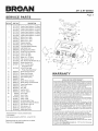
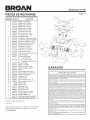
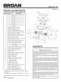
SERVICE PARTS
KEYNO,
1
4
5
6
7
8
9
10
11
12
13
14
PARTNO. DESCRIPTION
97017222
97017223
97017224
97017324
97017325
97017326
97009517
97007895
97007631
97017429
97007656
97017428
98006546
99400084
99271346
97017312
97017264
99111379
97017455
97017456
99420464
99150617
15 99170245
16 99260476
17 97007313
18 99100491
19 98005212
20 99080597
21 99020142
22 99020143
23 99400055
24 99500323
25 98010342
26 99260491
27 99260470
28 600348
600349
29 97016970
97016971
30 99260485
** 99400052
** 99770113
** 99770115
** 99030132
** 97016439
Feature Panel Weldment - RP-Black
Feature Panel Weldment -RP-White
Feature Panel Weldment - RP-Silver
Feature Panel Weldment - AP-Black
Feature Panel Weldment -AP-White
FeaturePanelWeldment- AP-Silver
BottomCover- Black
BottomCover- White
BottomCover- Silver
DamperAssembly
WireCoverAssembly
ThermostatBracketAssembly
LightSocketCover
BushingSplitHeyco#2873
Socket/TrimRingAssembly
Control-RP,Black
Control- RP,White
Spacer.50x .375Nylon
Filter,Aluminum(Qty.2)
Filter,AluminumwithMicroban(Qty.2)
BlowerMountingRod
8-18x .375TrussHead
SheetMetalScrew*
8-18x.375HexHead
PhillipsSheetMetalScrew*
BlowerMountingRodNut
BlowerScrollHousing
MotorIsolationBushing
MotorRetainingRing
Motor
BlowerWheel,Clockwise
BlowerWheel,Counterclockwise
HeycoSnapBushing
PVCFoam
Ring,Inlet
HexNut3/8-32
HexNut15/32-32
Knob- Black
Knob-White
Switch-Black
Switch-White
NutSheetMetalU-Type
BushingStrainRelief(NotShown)
WireHarness- NSP,RP
WireHarness- AP
RotaryFanControl
RotaryLightControl
* Standard hardware - may be purchased locally.
** Not illustrated
Order replacement parts by PART NO. -not by KEY NO.
Replacement parts can now beordered on our website.
Please visit us at www.broan.com.
12
25
23
6
Page 5
7
I8
/
4
15 i
WARRANTY
BROANONEYEARLIMITEDWARRANTY
Broanwarrantstotheoriginalconsumerpurchaserofitsproductsthatsuchproducts
will befreefromdefectsin materialsorworkmanshipfora periodof oneyearfrom
thedateoforiginalpurchase,THEREARE NOOTHERWARRANTIES,EXPRESS
OR IMPLIED,INCLUDING,BUTNOT LIMITEDTO, IMPLIEDWARRANTIESOF
MERCHANTABILITYORFITNESSFORAPARTICULARPURPOSE,
Duringthisone-yearperiod,Broanwill,atitsoption,repairorreplace,withoutcharge,
anyproductor partwhichis foundtobedefectiveundernormaluseand service,
THISWARRANTYDOESNOTEXTENDTOFLUORESCENTLAMPSTARTERS
AND TUBES.This warrantydoes notcover(a)normalmaintenanceandservice
or (b)any productsor partswhich havebeensubjecttomisuse,negligence,ac-
cident,impropermaintenanceorrepair(otherthan by Broan),faultyinstallationor
installationcontrarytorecommendedinstallationinstructions,
Thedurationofanimpliedwarrantyislimitedtotheone-yearperiodasspecifiedfor
theexpresswarranty.Somestatesdo notallowlimitationon howlonganimplied
warrantylasts,sothe abovelimitationmaynotapply toyou.
BROAN'S OBLIGATIONTO REPAIROR REPLACE,AT BROAN'SOPTION,
SHALLBETHEPURCHASER'SSOLEANDEXCLUSIVEREMEDYUNDERTHIS
WARRANTY.BROANSHALLNOTBELIABLEFORINCIDENTAL,CONSEQUEN-
TIALOR SPECIALDAMAGESARISINGOUT OFOR IN CONNECTIONWITH
PRODUCTUSE OR PERFORMANCE.Somestates do not allow theexclusion
or limitationof incidentalor consequentialdamages,so theabove limitationmay
notapplytoyou.
Thiswarrantygivesyou specificlegalrights,andyou mayalsohaveotherrights,
whichvaryfromstate tostate.Thiswarrantysupersedesallpriorwarranties.
Toqualifyforwarrantyservice,youmust(a)notifyBroanattheaddressortelephone
numberbelow,(b)givethemodelnumberandpartidentificationand(c)describe
thenatureof anydefectin theproductor part.At thetime ofrequestingwarranty
service,you mustpresentevidenceof theoriginalpurchasedate.
IntheUnitedStates,contact:Broan-NuToneLLC,926WestStateStreet,Hartford,
WI53027(1-800-637-1453)
InCanada,contact:Broan-NuToneCanada,Inc.,1140TristarDrive,Mississauga,
OntarioL5t1H9(1-888-882-7626)

SERIES APt ET RP
OTTE C
STYLE PROF I IE EL
Page 6
Pour enregistrer ¢e
produit, visitez:
WWW. broan.corn
POUR USAGE
AVERTISSEMENT
DOMESTIQUE SEULEMENT
AVERTISSEMENT ,
AFJN DE RCrDUIRE LES RISQUES D'INCENDIE, DE CHOC
ri=LECTRIQUE OU DE BLESSURES CORPORELLES,
VEUJLLEZ OBSERVER LES DIRECTIVES SUIVANTES :
1. N'utilJsez cet appareJl que de la maniere prevue par le fabricant. SJ
vous avez des questions, communiquez avec le fabricant a I'adresse
ou au numero de telephone indiques dans la garantJe.
2. Avant d'effectuer I'entretien ou le nettoyage de cet appareil,
coupez le courant au panneau electrique. Verrouillez ou installez
un sceau sur le panneau afin d'eviter que le courant ne soit retabli
accidentellement.
3. La pose de I'appareil et les travaux d'electricit6 (y comprJs la pose
de I'Jnterrupteur) doivent 6tre effectues par des personnes qualifiees
conformement a la reglementation en vJgueur, notamment lesnormes
de construction ayant trait ala protection contre les incendJes.
4. Pour eviter les refoulements, I'apport d'aJr doJt 6tre suffisant pour
brQler les gaz produits par les appareJJs a combustion et les
evacuer dans le conduit de fumee (cheminee). Respectez les
directives du fabdcant de I'appareJJ de chauffage et les normes de
securite, notamment celJes publiees par la National Fire Protection
Association (NFPA), I'Amedcan Society for Heating, Refrigeration
and Air Conditioning Engineers (ASHRAE) et lescodes des autorites
locales.
5. Ce produit peut comporter des arEtes tranchantes. Prenez garde
aux coupures et aux eraflures lots de I'installatJonet du nettoyage.
6. VeJllez & ne pas endommager Je c_blage electrique ou d'autres
equipements non apparents lots de la decoupe ou du pergage du
tour ou du plafond.
7. Les ventilateurs canalises doivent toujours rejeter I'air aI'exterieur.
8. N'utilisez que des conduits metalliques.
9. Ce produit peut egalement 6tre installe avec un ensemble de cordon
electrique homologue UL de conception speciale, en suivant les
instructions accompagnant I'ensemble de cordon electrique.
10. Cet appareil dolt 6tre relie a une raise a la terre.
POUR RCrDUIRE LES RISQUES D'INCENDJE CAUS¢:S PAR
DE LA GRABSE SUR LE PLAN DE CUBSON :
1. Ne laissez jamaJs Jes eJEments de surface allumes a haute
temperature. Les debordements peuvent causer de Ja fumee et
occasionner des ecoulements de graisse inflammables. L'huJJedolt
6tre chauffee graduellement a basse ou a moyenne temperature.
2. Mettez toujours la hotte en MARCHE lots de la cuisson a feu vJf
ou Iors de la cuisson d'alJments a flamber (par ex., crepes Suzette,
cerises jubiJe, boeuf au poivre flambe).
3. Nettoyez souvent la hotte. Ne laissez pas la graisse s'accumuler sur
le ventilateur ou Jefiltre.
4. UtJiJsez des casseroles de dimension appropriee. Utilisez toujours
une battene de cuisine adaptee a la dimension de la surface
chauffante.
OBSERVEZ LES CONSIGNES SUIVANTES DE MANI€:RE A
R#DUIRE LES RISQUES DE BLESSURES CORPORELLES
EN CAS D'INCENDJE CAUSe: PAR DE LA GRABSE SUR LE
PLAN DE CUISSON :*
1. ETOUFFEZ LES FLAMMES a I'aJde d'un couvercle etanche,
d'une t61e a biscuits ou d'un plateau en metal puJ,s eteignez le
brQieur. FAITES ATTENTION DE NE PAS VOUS BRULER. SI LES
FLAMMES NE S'ETEIGNENT PAS IMMEDIATEMENT, QUITTEZ
LES LIEUX ETAPPELEZ LES POMPIERS.
2. NE SOULEVEZ JAMAIS UNE CASSEROLE EN FLAMMES- vous
pourriez vous brQler ou propager I'Jncendie.
3. N'UTILISEZ PAS D'EAU, ni de serviettes ou de linges mouilles - une
violente explosion de vapeur pourrait survenir.
4. Utilisez un extincteur SEULEMENT si :
A. Vous savez qu'il est de classe ABC et vous connaissez deja son
mode de fonctJonnement.
B. L'incendie n'est pas tres important et ne se propage pas.
C. Les pompiers ont ete avises.
D. Vous pouvez combattre I'incendie en faisant dos a une sortie.
* Conseils tires de la publication de la NFPA <<Kitchen Fire Safety Tips >>.
ATTENTION
1. Cet appareJl ne doit servir qu'a la ventilation generale. Ne pas
I'utiliser pour I'evacuation de matieres ou de vapeurs dangereuses
ou explosives.
2. Pour un captage optimal des impuretes, installez la hotte de sorte
que sa partie inferieure soit entre 46 et 61 cm (18 et 24 pouces) au-
dessus de la surface de cuisson.
3. Veuillez lire I'etiquette de specifications du produJt pour obtenir plus
de renseignements, notamment sur les exigences.
_Ces correspondent aux
instructions uniQ_uernent
installations avec conduits,
Si la hotte est installee sans conduit •
Veuillez vous procurer un ensemble de filtres pour hotte sans
conduit chez votre distributeur local ou votre detaillant, (Disponible
pour hottes de serie AP1 et RP2 seulement,) Suivez les instructions
accompagnant I'ensemble pour hotte sans conduit,
lnstallateur : Veuillez remettre ce manuelau proprietaire.
Proprietaire : Nettoyage,entretien et moded'emploi a la page7.

SERIES APt ET RP
NETTOYAGE ET ENTRETIEN
Pour des raisons de sante, de performance et d'apparence, nettoyez le
filtre, le ventilateur et les surfaces graisseuses. Utilisez seulement un
chiffon propre et une solution de detergent doux sur I'acier inoxydable et
les surfaces peintes. Lavez les filtres d'aluminium au lave-vaisselle.
Le moteur est lubrifie en permanence et n'a pas besoin d'6tre huile. Si
les roulements du moteur sont anormalement bruyants, remplacez le
moteur exactement par le m6me modele. La roue a ailettes dolt aussi
6tre remplacee.
Utilisez des ampoules halogenes avec ecran de 120 V, 50 W - MR16 ou
PAR16 a culot GU10. Les ampoules sont vendues separ6ment.
Les filtres a graisses, le panneau inf@ieur et ia roue a ailettes doivent
6tre nettoyes frequemment. Utilisez une solution tiede de detergent. Les
filtres a graisses et la roue a ailettes sont lavables au lave-vaisselle.
Remarque : Certains min@aux, Iorsqu'ils entrent en contact
avec les additifs des savons pour lave-vaisselle, peuvent
decolorer les filtres. Cette decoloration n'est pas couverte par
la garantie.
FONCTIONNEMENT
Mettez toujours la hotte en MARCHE avant de cuisiner afin d'etablir une
circulation d'air dans la cuisine. Laissez la hotte fonctionner quelques
minutes apres I'arr6t de la cuisini@e afin de nettoyer I'air.
DC:TECTEUR HEAT SENTRY Mc
Votre hotte est equip6e d'un thermostat HEAT SENTRY Me.II s'agit d'un
detecteur de chaleur qui actionne le ventilateur ou en augmente le regime
en cas de chaleur excessive degag6e par les el6ments de cuisson.
Si le ventilateur est arr6t6 ou tourne a bas regime, le detecteur Heat
Sentry Mcsupplante la commande normale du ventilateur et I'actionne
haut regime, Une fois la temp@ature revenue a la normale, le ventilateur
revient a son reglage d'origine,
HOTTE DE St_RIE RP
Pour utitiser la hotte, faites comme suit :
__ [] I p BROAN 0 I 2 X
_ INTERRUPTEUR DU VENTILATEUR
Cet interrupteur a trois positions met la hotte en MARCHE, sur ARRET
et commande la vitesse du ventilateur,
Placez I'interrupteur sur (1) pour mettre le ventilateur en MARCHE au
regime lent,
Placez I'interrupteur sur (2) pour mettre le ventilateur en MARCHE au
regime elev6,
Placez I'interrupteur sur (0) pour mettre le ventilateur sur ARRET,
':_ INTERRUPTEUR D'C:CLAIRAGE
Cet interrupteur a trois positions permet d'ALLUMER et d'ETEINDRE les
lumi@es et de commander leur intensite.
Placez I'interrupteur sur (1) pour ALLUMER les lumieres a faible intensite.
Placez I'interrupteur sur (2) pour ALLUMER les lumi@es &haute intensite.
Placez I'interrupteur sur (0) pour ETEINDRE les lumi@es.
HOTTE DE SCRIE AP
Pour utitiser la hotte, faites comme suit
0 • 0
Page 7
0
VENTILATEUR
L'interrupteur a deux positions (au centre) actionne ou arr6te le
ventilateur.
L'interrupteur a cinq positions (a gauche) commande la vitesse
du ventitateur.
O Le ventilateur est ARRETE (ventilateur secondaire ARRETE).
• Le ventitateur est en MARCHE au regime etev6.
• ® • Plus les points sont petits - plus le regime diminue.
LAMPE
Cet interrupteur a trois positions permet d'ALLUMER et
d'E_TEINDRE les tumieres et de commander leur intensite.
O Les lumieres sont €:TEINTES.
(_ Les lumieres sont ALLUM¢:ES a faible intensite.
Les lumi@es sont ALLUM¢:ES a haute intensite.
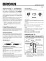
PRI PARATION DE
L'EMPLACEMENT DE LA HOTTE
CAPUCHON DETOIT CONDUIT 8,3 x 25,4 cm
(3-1/4 X 10 po.)
Pour evacuation verticale)
SOFFITE _ C,&,BLAGE ELECTRIQUE
Haut ou arriere de la hotte)
CAPUCHON MURAL
-T
46 tk 61 CM (18 A 24 PO.)
AU-DESSUS DE
LA SURFACE DE CUISSON
CONDUIT 8,3 x 25,4 cm
(3-1/4 X 10 po.) (Pour
evacuation horizontale)
El Determinez si I'evacuation de la hotte sera verticale ou
horizontale, Que I'evacuation soit verticale ou horizontale,
installez les conduits entre la hotte et le capuchon mural ou de
toit, Pour obtenir les meilleurs resultats, utilisez un minimum de
coudes et de transitions,

SERIES APt ET RP
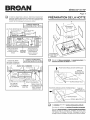
ik I'aide des diagrammes ci-dessous, determinez I'emplacement
exact des coupes a effectuer pour le conduit et le fil d'alimentation
electrique dans I'armoire ou lemur. Pour une installation sans
conduit, NE PAS decouper de trou pour le conduit.
i CONDUIT VERTICAL
8,3 X 25,4 CM (3-1/4 X 10 PO.)
(4) VIS DE MONTAGE DE LA HOTTE
31 cm (12-1/4 po.) 31cm (12-1/4 po.)
hotte de 30 po.) L,.,.._te ae 6u po.)
38 6 cm(15-1/4 po.)l 38,6 cm(15-1/4 po.)
hotte de 36 po.) "I (hotte de 36 po.)
-AVANT DE L'ARM IRE
r-l-t 0EssousoE, 19cm
I|27:5ocm L'ARMOIRE _ (7-I/2po.)=_.I I I_
|_b-//_ po.) 15,8 cm I 15,8 cm "125,t cml
| _L_ I_O-l/4po. 6-1/4po._ _9-7/8po)I
! 270m I TROUPOUR I/ I I:
_ I<10.5/8po-)I CONI]'UI_- _!ERTIOAL | _ t!:
I-\"
CALES DE BOIS t
(seulement pour LIGNE DE
armoires & base en CENTRE
retrait)
_L
3,8 cm
ml/2 po.)
3
TROU POUR FIL
D'ALIMENTATION
€:LECTRIQUE
(dans le dessous
de I'armoire)
Page 8
PRI=PARATION DE LA HOTTE
I
COUVERCLE
DU BOtTlER DE
CABLAGE
CALES DE BOIS
(armoires a dessous
encastre seulement)
l CONDUIT HORIZONTAL
8,3 X 25,4 CM (3-1/4 X 10 PO.
AVANT DE L'ARMOIRE 1,9 cm (3/4 po.)
0,3cm (1/8 po.) i
k----. 1
TROU POUR T
DESSOUS CONDUITHORIZONTAL
nu H^pMn pu _, 15,8 cm =_ .15,8 cm
.............. (6-1/4 po.) 16-1/4po. _or
I 31cm(12-1/4p0.)(hottede30p0.) _ '2I
_ 31cm(12-1/4p0)(h
3'°86cm(151/4p0)(hottede36p0)
' - ' ' 38,6cm(15-1/4i0.)(hottede36p0.)
,(4) VlS DE f TROU POUR FIL
MONTAGE LIGNE DE D'ALIMENTATION
DE LA HOTTE CENTRE €:LECTRIQUE
(dans lemur)
5] Enlevez les filtres en aluminium le couvercle du fond et le
couvercle du boitier de c_blaq#, de la hotte.
tPOSITION D'EVACUATION VERTICALE
-- TIGE DE
-- MONTAGE DU
_JJf?Z'-_o_\ I _ VENTILATEUR
POSITION D'EVACUATION HORIZONTALE TIGE DE
...... _.. i _. MONTAGE DU
F t_,, ",,o I _VENTILATEUR (2)
EL
[!1 Le ventilateur est livre en position d'_vacuation verticale.
Pour placer le ventilateur en position d'6vacuation horizontale •
Enlevez les _crous molet_s des tiqes de montaqe du ventilateur.
Degagez les tiges de montage du ventilateur et tournez celui-
ci en position d'evacuation horizontale. Reengagez les tiges de
montage et fixez le ventilateur en place avec les ecrous moletes.

SERIES APt ET RP
Page 9
CLAPET/ ? RACCORD DU C.&,BLAGE
I
RACCORD DE _
CONDUIT __ ? OUVERTURE
PRI_AMORCI_E
VERTICALE
/
/i / ///
OUVERTURE PREAMORCI_E
•"HORIZONTALE
VIS VERTE
DE MISEA
LA TERRE
Connectez le fil d'alimentation _lectrique a la hotte en raccor-
dant le fil NOIR au fil NOIR, le fil BLANC au fil BLANC, et le fil
VERT ou le FIL D#NUDI_ a la vis VERTE de raise _ la terre.
3 Enlevez I'ouverture pr6amorc_e verticale ou I'ouverture
pr_amorc_e horizontale et fixez le clapet /raccord de
conduit avec deux (2) vis (fournies).
INSTALLATION DE LA HOTTE
_ VERTISSEMENT
Pour reduire les risques de choc electrique, coupez le courant
du panneau electrique. Verrouillez ou posez un sceau sur le
panneau afin d'eviter que le courant ne soit retabli accidentel-
lement.
VlS DE
MONTAGE (4)
JO FIL
D'ALIMENTATION
ELECTRIQUE
of
IA,__I'!
l> <,.nl
CONDUITS
El
El
El
Acheminez le fil d'alimentation _lectri Ue_huedu panneau elec-
trique jusqu'a I'emplacement de la hotte. Fixez le fil d'alimentation
la hotte avec le connecteur appropri&
Maintenez la hotte en place sous I'armoire. Assurez-vous que le
clapet /raccord de conduit s'insere a I'interieur du conduit et que
le clapet s'ouvre et se ferme librement.
Serrez completement les quatre (4) vis de montage: pour fixer la
hotte sous I'armoire.
TERMINER L'INSTALLATION
Reinstallez le couvercle du boftier de le couvercle du
c_blage,
fond et les filtres enleves a I'etape 3.
INSTALLATIONDESAIVlPOULES
t
(2) TOURNER
VERS LA DROITE
I_ Installez les ampoules haloq_nes. Utilisez des ampoules
halogenes avec ecran de 120 V, 50 W - MR16 ou PAR16 a culot
GU 10. Les ampoules sont vendues separ6ment.

SERIES APt ET RP
PIECES DE RECHANGE
REPEREN°DEPIECE.
1 97017222
97017223
97017224
97017324
97017325
97017326
97009517
97007895
97007631
97017429
97007656
97017428
98006546
99400084
99271346
97017312
97017264
99111379
97017455
97017456
99420464
99150617
4
5
6
7
8
9
10
11
12
13
14
15 99170245
16 99260476
17 97007313
18 99100491
19 98005212
20 99080597
21 99020142
22 99020143
23 99400055
24 99500323
25 98010342
26 99260491
27 99260470
28 600348
600349
29 97016970
97016971
30 99260485
** 99400052
** 99770113
** 99770115
** 99030132
** 97016439
DESCRIPTION
BoTtlersoude - RP-Noir
BoTtlersoude - RP-Blanc
BoTtlersoude - RP-Argent
BoTtlersoude - AP-Noir
Boftier soude - AP-Blanc
Bottler soude - AP-Argent
Couvercle de fond - Noir
Couvercle de fond - Blanc
Couvercle de fond - Argent
Ensemble de clapet
Ensemble de couvercle de c_blage
Ensemble de support de thermostat
Couvercle de douille de lumi@e
Manchon, butee fendue, n° 2873
Ensemble de douille/contour
Commande - RP, Noire
Commande - RP, Blanche
Cale .50 x .375 pc. en nylon
Filtre, aluminium (qte 2)
Filtre, aluminium avec Microban (qte 2)
Tige de montage
Vis a t61ea t¢te bombee
n° 8-18 x 0,375 pc.*
Visa t61ecruciforme a tCte
hexagonale n° 8-18 x 0,375 pc.
Ecrou de montag
Boftier du ventilateur
Manchon isolant du moteur
Anneau de retenue du moteur
Moteur
Roue a ailettes, sens horaire
Roue a ailettes, sens antihoraire
Manchon, butee fendue
Mousse en PVC
Anneau, entree
Ecrou hexagonal 3/8 pc. - 32
Ecrou hexagonal 15/32 pc. - 32
Bouton -Noir
Bouton -Blanc
Interrupteur -Noir
Interrupteur -Blanc
Ecrou a t61e,Type U
Bride de cordon (non illustre)
Socle de c_blage - NSP, RP
Socle de c_blage - AP
Commande rotatoire de ventilateur
Commande rotatoire de lumiere
* Quincaillerieordinairevendues@ar6ment.
** Nonillustr6.
Veuillezcommanderlespi_cesparN° DEPIECEet nonpar N° DEREPERE.
Lespi_cesderechangepeuvent_trecommand6essur notresiteWeb.
Visitezwww.broan.com.
12
25
23
6
Page 10
7
!8
15
GARANTIE
GARANTIE LJMITEE D'UNAN DE BROAN
Broangarantit _ I'acheteur consommateur original de ses produits quils sont exempts de
vice de materiaux ou de fabrication pour une periode d'un an _ compter dela date d'achat
original. ILN'YA PASD'AUTRES GARANTIES, EXPRIMEESOU IMPLICITES,INCLUANT
MAIS NON LIMITEES AUX GARANTIES IMPLICITES DE QUALITE MARC14ANDEET DE
CONVENANCE DANS UN BUT PARTICULIER.
Durantcette p@ioded'un an, Broan, _ sa discr6tion, r@arera ou remplacera gratuitement
tout produit ou piece qui s'av@era d6fectueux et ayant et6 utilis6 normalement et d'une
maniere nonabusive.
CETTE GARANTIENE COUVREPAS LESSTARTERSDETUBES FLUORESCENTSNI LES
TUBES FLUORESCENTS.Cettegarantie ne couvrepas (a)I'entretien et leservice normalou
(b)tout produit ou piece endommage a la suite d'un mauvais usage d'une n6gligence, d'un
accident, d'unentretien inad@uat ou d'une r@aration (autre que par Broan),d'une mauvaise
installationou d'une installation nonconforme au moded'installation recommand&
Laduree de toute garantie im,pliciteest limitee _ unep@iode d'un an tel que sp6cifi6 pourla
garantie exprim6e. Certains Etats ou provinces ne permettent pas de limitation de la duree
d'une garantie implicite. Cettecondition ne s'applique donc peut-_tre pas dans votre cas.
L'ENGAGEMENTDE BROAN/_ REPARER OU _,REMPLACER, AU CHOIX DE BROAN,
SERA LA SEULE OBLIGATION EXCLUSIVE SOUS CETTE GARANTIE BROAN NE SE
TIENDRA PASRESPONSABLE DES DOMMAGES DIRECTS,INDIRECTS OUSPEClAUX
AYANTUN LIENDIRECT OU INDIRECTAVEC L'UTILISATIONOULA PERFORMANCE DE
SES PRODUITS. Certains Etats ou provinces ne permettent pas I'exclusion ou la limitation
de dommages directs ou indirects. Cette condition nes'applique doric peut-6tre pas dans
votre cas.
Cette garantie vous donne des droits specifigues et il se peut que vous ayez d'autres droits
qui varient d'une province a I'autre ou d'un Etat _ {'autre. Cette garantie annule toutes les
garanties prec6dentes.
Pourle servicesousgarantie,vous devez(a)aviser Broan _I'adresseou num@ode t_l@hone
mentionnee cFdessous, (b) donner le num@oou le mod¢leet Hdentification de la piece et
(c)decrire la nature detout d_faut dans le produit ou la piece. Au moment de la demande
de service sous garantie, vous devez presenter une preuve de la date d'achat original du
produiten question.
Aux Etats-Unis,contactez: Broan-NuTone LLC 926 West State Street, Hartford Wl 53027
(1-800-637-1453)
Au Canada,contactez:Broan-NuTone Canada, Inc., 1140Tristar Drive, Mississauga,Ontario,
L5T 1149(1-888-882-7626)

SERIE AP1 Y RP
ESTILO ACOC A
PROFESIONAL
P#gina 11
Para registrar este
producto visite:
WWW. broari.con3
SOLAMENTE PARA
ADVE.TE.CIA COCINAR EN CASA
ADVE.TE.CIA
PARA P,EDUCIP, EL P,IESGO DE INCENDIOS, DESCAP,GAS
EL#CTP,ICAS O LESIONES PEP,SONALES, OBSERVE LAS
SIGUIENTES PP,ECAUCIONES:
1. Use la unidad s61o de la manera indicada por ei fabdcante. Si tiene
preguntas, comuniquese con el fabricante a la direcci6n o al nQmero
telef6nico que se incluye en la garantia.
2. Antes de dar servicio a la unidad o de limpiarla, interrumpa el
suministro electrico al panel de servicio. BIoquee el panel de servicio
o p6ngale una etiqueta de seguridad para evitar que alguien conecte
accidentalmente la energia electrica.
3. El trabajo de instalaci6n y cableado electrico (incluida la ubicaci6n
del interruptor) debe set realizado pot personal calificado y de
conformidad con todos los c6digos y normas correspondientes,
incluidos los de construcci6n especificos contra incendios.
4. Proporcione suficiente aire para que se Ileve acabo la combusti6n
yescape adecuados de los gases a traves del tubo de humos
(chimenea) del equipo quemador de combustible, afin de evitar
el contratiro. Siga las normas de los equipos de combusti6n tales
como las establecidas en los c6digos locales y las publicadas por
la Asociaci6n Nacional de Protecci6n contra Incendios (National
Fire Protection Association, NFPA) y la Sociedad Americana de
Ingenieros de Calefacci6n, Refrigeraci6n y Aire Acondicionado
(American Society for Heating, Refrigeration and Air Conditioning
Engineers, ASHRAE).
5. Este producto podria tener bordes afilados. Trabaje con cuidado para
evitar cortadas y abrasiones durante la instalaci6n y la limpieza.
6. AI cortar o perforar a traves de la pared odel cielo raso, tenga cuidado
de no dafiar el cableado electrico ni otros servicios ocultos.
7. Los ventiladores con conductos siempre deben conectarse hacia el
exterior.
8. Utilice Qnicamente conductos metalicos.
9. Como alternativa, se puede instalar este producto con el juego de
cable de alimentaci6n aprobado pot UL y disefiado para el producto,
siguiendo las instrucciones incluidas con el cable.
10. Esta unidad debe conectarse a tierra.
PARA REDUCIR EL RIESGO DE INCENDIO PP,OVOCADO
POP, GRASA PP,ESENTE EN LA ESTUFA:
1. Nunca deje desatendidas las unidades de la superficie cuando
esten en ajustes altos de calor. Los alimentos en ebullici6n provocan
derrames grasosos y con humo que se pueden inflamar. Caliente el
aceite lentamente en ajustes de calor bajo o medio.
2. Siempre ENCIENDA la campana cuando este cocinando a altas
temperaturas o flamee alimentos (pot ejemplo crepas Suzette,
cerezas Jubilee, bistec con pimienta flameado).
3. Limpie frecuentemente los ventiladores. No se debe permitir la
acumulaci6n de grasa en el ventilador ni en el filtro.
4. Use una cacerola del tamafio adecuado. Siempre use utensilios
de cocina que sean apropiados para el tamafio del elemento de la
superficie.
PARA P,EDUCIR EL RIESGO DE LESIONES A LAS
PERSONAS EN CASO DE UN INCENDIO PRODUCIDO POP`
GP,ASA EN UNA ESTUFA, OBSERVE LO SIGUIENTE*:
1. APAGUE LAS LLAMAS con una tapa de ajuste exacto, una charola
para galletas o una bandeja de metal, y despues apague el quemador.
PROCEDA CON CUIDADO PARA EVITAR QUEMADURAS. Si las
llamas no se apagan inmediatamente, EVACUE EL AREA Y LLAME
A LOS BOMBEROS.
2. NUNCA LEVANTE UNA CACEROLA INCENDIADA porque podria
sufrir quemaduras o propagar el incendio.
3. NO TRATE DE APAGAR EL FUEGO CON AGUA ni con trapos o
toallas de cocina mojados, pues ocasionara una explosi6n violenta
de vapor.
4. Use un extintor SOLO si:
A. El extintor es de Clase ABC y usted sabe c6mo hacerlo
funcionar.
B. El incendio es pequefio y esta confinado al area en la que se
InlcIO.
C. Va a Ilamar al DepaFtamento de Bomberos.
D. Puede combatir el incendio teniendo la espalda orientada hacia
una salida.
*Basado en "Kitchen Fire Safety Tips" (Sugerencias para la seguridad
contra incendios en la cocina) publicado pot NFPA.
PRECAUCION
1. S61o para usarse como medio de ventilaci6n general. No debe
usarse para la extracci6n de materiales ni vapores peligrosos o
explosivos.
2. Para capturar mejor las impurezas resultantes al cocinar, debe
montar la parte inferior de la campana auna altura de 18 a 24 pulg.
(46 a 61 cm) sobre la superficie para cocinar.
3. Lea la informaci6n y los requisitos que aparecen en la etiqueta de
especificaciones.
E_ Estas instrucciones son solamente para
instalaciones con conductos.
Si la campana se va a instalar en un sistema sin conductos:
Compre un juego de filtros sin conductos con su distribuidor
o tienda minorista local. (Disponible para campanas de
la serie API y RP2 solamente.) Siga las instrucciones
incluidas con este juego de filtros.
Avisoal instalador:Dejeestemanual con eldueho de la casa.
Avisoal dueho de la casa:En la p&gina12encontrar&las instruccionesde limpieza,
mantenimiento yfuncionamiento.

SERIE AP1 Y RP
P4gina 12
LIMPIEZA Y MANTENIMIENTO CAMPANA SERIE AP
Para hacer funcionar la campana, haga to siguiente:
Por motJvos de desempeSo, apariencia y salud, IJmpie el filtro, el
ventilador y las superficies que tengan grasa. Utilice t_nicamente un
trapo limpio y una soluci6n de detergente suave en superficies de acero
inoxJdable y pintadas. Limpie los filtros completamente metaficos en el
lavaplatos.
El motor esta permanentemente lubricado y nunca necesitara aceite.
Si los cojJnetes del motor estan hacJendo ruido excesivo o inusual,
reemplace el motor con el motor de servicio exacto. Tambien debe
reemplazar el impulsor.
UtilJce bombJllas de hal6geno con escudo protector de 120V, 50 W (MR16
o PAR16 con base GU10). Las bombillas se compran pot separado.
Los filtros de grasa, el panel inferior y el disco del ventilador deben
IJmpJarse con frecuencJa con una soluci6n tibia de detergente y agua.
Los filtros de grasa y el disco del ventilador pueden lavarse en un
lavaplatos.
Nota: Ciertos mJnerales causan la decoloracJ6n de los filtros
al ponerse en contacto con los aditJvos de los detergentes
lavaplatos. Esta decoloraci6n no esta cubierta pot la
garantJa.
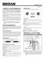
FUNCIONAMIENTO
0 • 0
ON FAN OFF
FAN LIGHT
BR N
0
VENTILADOR
El Jnterruptor de 2 posiciones (en el centro) ENCIENDE y APAGA el
ventiiador.
El interruptor de 5 posiciones (a la izquierda) controla la velocidad del
ventilador.
O El ventilador esta APAGADO (el ventilador secundario esta APAGADO).
O El ventilador esta ENCENDIDO a su maxima veJocJdad.
• ® ®Mientras mas pequehos sean los puntos, menor sera la velocidad
del ventJlador.
ENCIENDA siempre la campana antes de comenzar a cocinar, a fin de
establecer un flujo de aire en la cocina. Despues de apagar la estufa,
deje que la campana funcione durante unos cuantos mJnutos para
despejar el aire.
Termostato HEAT SENTRY TM
La campana est4t equipada con un termostato Heat Sentry TM. Este
dispositivo de seguridad encendera el ventilador o aumentara su
velocidad si detecta un calor excesivo sobre la superficie de cocinado.
SJ el ventJlador no esta encendido o sJ funciona a baja velocJdad, el
termostato Heat Sentry TM anulara el control que tenga el ventJlador y
Io hara funcionar a alta velocJdad. Cuando la temperatura dismJnuye a
niveles normales, el ventilador regresa a su ajuste original.
CAMPANA SERIE RP
Para hacer funcionar la campana, haga Io siguJente:
0 I 2 0 I 2
INTERRUPTOR DEL VENTILADOR
Este interruptor de 3 posiciones ENCIENDE y APAGA el ventilador y
controla su velocJdad.
Ponga el Jnterruptor en la posici6n (1) para ENCENDER el ventilador a
baja velocidad.
Ponga el Jnterruptor en la posici6n (2) para ENCENDER el ventilador a
alta velocidad.
Ponga el interruptor en la posici6n (0) para APAGAR el ventilador.
"_ INTERRUPTOR DE LUZ
Este Jnterruptor de 3 posiciones ENCIENDE yAPAGAlas luces y controla
su Jntensidad.
Ponga el interruptor en la posici6n (1) para ENCENDER las luces a baja
intensidad.
Ponga el interruptor en la posici6n (2) para ENCENDER las luces a alta
intensidad.
Ponga el interruptor en la posici6n (0) para APAGAR las luces.
LUCES
Este Jnterruptor de 3 posicJones (a la derecha) ENCIENDE yAPAGA las
luces y controla su intensidad.
O Las luces estan APAGADAS.
(_ Las luces estan ENCENDIDAS con baja intensidad.
Las luces estan ENCENDIDAS con alta intensidad.
PREPARE EL LUGAR DONDE
SEVAA INSTALARLACAMPANA
TAPON DE TECHO CONDUCTO DE
3¼pulg. xl0pulg.
(8,3x25,4cm)
(paradescargave_ical)
E3
CAM PANA
DE 46 cm a 61 cm (18 a 24 pulg.)
SOBRE LA SUPERFICIE PARA
COCINAR
CA BLEADO
ELEC,TRICO
(parte superior o
posterior de la
campana)
TAPON DE
PARED
CONDUCTO DE
3 t/4pulg. x 10 pulg.
(8,3 x 25,4 cm )
(para descarga
horizontal)
Determine si la descarga de la campana va a ser vertical o
horizontal, Para descarga vertical u horizontal, coloque la red
de conductos entre el lugar donde va a Jnstalar la campana y
el tap6n de techo o tap6n de pared, Para obtener los mejores
resultados, utilice una cantidad minima de transiciones y
codos,

SERIE AP1 Y RP
P4gina 13
GuieseporeJdJagramacorrespondiente(acontinuaci6n)para PREPARE LA CAMPANA
colocar Josconductos y hacer el corte exacto para la conexi6n
eJectrica en el gabinete o en Ja pared. Para instaJaciones en
sistemas sin conductos, NO haga ningQn orificio de acceso para
conducto.
i CONDUCTO VERTICAL DE
3%PULG. X 10 PULG. (8,3 X 25,4 CM
TORNILLOS DE MONTAJE DE LA CAMPANA (4)
12 ¼ pulg. (31cm ) 12 ¼ pulg. (31cm)
(campana de 30 pulg.) (campana de 30 pulg.)
,,=15 ¼ pulg. (38.6 cm_.._15 ¼ pulg. (38,6 cm)=_
(campana de 36 pulg.) - I " (campana de 36 pulg.)
"FRENTE DEL GABJNETE
"_!_ '--t' FOND0 DEL'1 7 ½ u, --l"""r
I I;"U! (17.5cm) 6¼putg. I 6¼putg. - _ _:
II;| _ !'_" (15.8 cm )'_"_(15.8 cm y'_d °_c-- !:;
_::,]!0_pulg. I 0R,F,O,ODEAOOESOI _._ I_:
II:o:,l(_7cml_ _ [:
, k-
CUKIAS DE MADERA f
(s61o gabinetes de LINEA
rondo empotrado) CENTRAL
_L
1 1/2 pulg.
(3,8 cm)
-r
9 pulg.
(22,8 cm)
ORIFICIO DE ACCESO
PARA CABLES
ELECTRICOS
(en el fondo del gabinete)
I I
i j
_ FILTROS DE
ALUMINIO '
/
CUBIERTA
DEL
CABLEADO
CONDUCTO HORIZONTAL DE
3%PULG. X 10 PULG. (98,3 X 25,4 CM
CUNAS DE MADEIRA
(s61o gabinetes de
fondo empotrado) FRENTE DEL 3/4pulg.
E 1 (I,9 cm) ,
½ pulg.
k/, I/
= :IR
/ (9,8 cm) | PARACONDUCT0 HORIZONTAL II
FONDO _ [ [ II
DELGABINETEl_-9,_2u'g:-_-,6,_2u'g;-4
_I_,_cm) j _I_,_cm)
12 ¼ pulg.(31cm) _ 7//2pul
(campanade 30 pulg.).,_] (19cm)
-_1/ ...... _ I.,_.-. 12 _¼pulg. (31 cm)
}1b /4 puIg; (3_,U c.m) I - (campana de30pulg.)
(campana de 4b pulg.) _15_¼pulg. (38.6 cm)
|(campana de36pulg.)
TORNILLOS DE LJNEA ORIFICIO DE
MONTAJE DE LA CENTRAL ACCESO PARA
CAMPANA (4) CABLES ELI'--CTRICOS
(en la pared)
Quite de la campana los flltros de aluminio la cubierta inferior
y la cubierta del cableado.
t POSICION DE DESCARGAVERTICAL
-- VARILLA DE
-- MONTAJE DEL
_/-_-_'-,, I _ VENTILADOR
POSlCION DE DESCARGA HORIZONTAL VARILLA DE
MONTAJE DEL
E-_"---""\° I _ VENTILADOR
[!1 El ventilador se envia en la _,oosici6n de descarcja vertical.
Para cambiar el ventilador a la j_osJcJ6n de descaLcLa horizontal:
Retire las tuercas moleteadas de las varillas de montaeLdel
ventilador. Desenganche las varillas de montaje del ventilador
y gire este a la posici6n de descarga horizontal. Enganche de
nuevo las varillas de montaje y apriete el ventilador en su lugar
con las tuercas moleteadas.

SERIE AP1 Y RP
PDgina 14
CONECTOR DEL II
i
REGULADOR DE i
TIRO/CONDUCTO_
AGUJERO CIEGO DEL
CONDUCTO VERTICAL
/
ii I iii
_" /AGUJERO CIEGO DEL
i>" CONDUCTO HORIZONTAL
Abra el a_clO del conducto vertical o el
c_lo del conducto horizontal y fije el conector del
requlador de tiro/conducto con dos (2) torniNos (incluidos).
INSTALE LA CAMPANA
CONECTE EL CABLEADO
TORNILLO
VERDE DE
CONEXION
ATIERRA
CABLE
DE LA
CASA
I_ Conecte el cable el_ctrico de la casa al cableado de la cam-
pana de cocina: cable NEGRO con NEGRO, BLANCO con
BLANCO y VERDE o SIN FORRO al tornillo de tierra VERDE.
FINALICE LA INSTALAClON
_ DVERTENCIA
Para reducir el riesgo de una descarga electrica, desconecte
el sumJnistro electrico al panel de servicio. Bloquee el panel
de servicio o p6ngale una etiqueta de seguridad para evitar
que alguien conecte accidentalmente la energia electrica.
m
TORNILLOS DE
MONTAJE (4)
j! © CABLE
EL#CTRICO
DE LA CASA
oI
<l> <,>'!I
CONDUCTO
m
m
I_ Tienda el cable el_ctrico de la entre el de servicio
casa panel
y la campana. Conecte el cable electrico a la campana con un
conector apropiado.
I_ Sostenga campana en su posici6n debajo gabinete.
la del
AsegQrese de que el conector del regulador de tiro/conducto en-
tre a los conductos y que el regulador de tiro pueda abrirse y
cerrarse libremente.
[_ Apriete completamente (4) montaj#_ para
los cuatro tornillos de
afianzar la campana al gabinete.
1_ Instale nuevamente la cubierta la cubierta inferior
para cableado,
y los filtros que quit6 en el paso 3.
INSTALE LAS BOMBILLAS
t
(2) GIRAR EN
SENTIDO DE
LAS AGUJAS
DEL RELOJ
Instale las bombillas de hal6 eqeno. Utilice bombillas de hal6geno
con escudo protector de 120 V, 50 W (MR16 o PAR16 con base
GU10). Las bombiNas se compran por separado.

SERIE AP1 Y RP
PIEZAS DE REPUESTO
CLAVEN.° PIEZAN. °
1 97017222
97017223
97017224
97017324
97017325
97017326
3 97009517
97007895
97007631
4 97017429
5 97007656
6 97017428
7 98006546
8 99400084
9 99271346
10 97017312
97017264
11 99111379
12 97017455
97017456
13 99420464
14 99150617
15 99170245
16 99260476
17 97007313
18 99100491
19 98005212
20 99080597
21 99020142
22 99020143
23 99400055
24 99500323
25 98010342
26 99260491
27 99260470
28 600348
600349
29 97016970
97016971
30 99260485
** 99400052
** 99770113
** 99770115
** 99030132
** 97016439
DESCRIPCION
Conjuntosoldadodel paneldefunciones-
RP- Negro
Conjuntosoldadodel paneldefunciones-
RP- Blanco
Conjuntosoldadodel paneldefunciones-
RP- Plata
Conjuntosoldadodel paneldefunciones-
AP- Negro
Conjuntosoldadodel paneldefunciones-
AP- Blanco
Conjuntosoldadodel paneldefunciones-
AP - Plata
Cubiertainferior- Negra
Cubiertainferior- Blanca
Cubiertainferior- Plata
Conjuntodel reguladordetiro
Conjuntodela cubiertaparaloscables
Conjuntodelsoporteparael termostato
Cubiertadel portaDmpara
SeparadordecasquilloHeycoN.° 2873
Conjuntodearc portaDmpara/moldura
Control- RP- Negro
Control- RP- Blanco
Separadorde0,50 x 0,375 pulg.de nailon
Filtrodealuminio(cant.2)
FiltrodealuminioconMicroban(cant.2)
Varilla demontajedel ventilador
Tornillomet_licocabezaredonda
8-18x 0,375pulg.*
Tornillomet_licoPhillipscabezahexagonal
8-18x 0,375pulg.*
Tuercaparavarillademontajedel ventilador
Cajadela espiraldel ventilador
Bujeparaaislamientodel motor
Anillo retenedordel motor
Motor
Discodelventilador,giroa la derecha
Discodelventilador,giroa la izquierda
BujedecierreHeyco
EspumadePVC
Arc, entrada
Tuercahexagonal,3/8pulg.- 32
Tuercahexagonal,15/32pulg.- 32
Perilla- Negra
Perilla- Blanca
Perilla- Negra
Interruptor-Blanco
Tuercamet_licatipo U
Bujedealiviode esfuerzo(nose ilustra)
Mazodecables- NSP,RP
Mazodecables- AP
Controlrotatoriodelventilador
Controlrotatoriode la luz
* Tornilleria estandar: se puede comprar en una ferreteria de la Iocalidad.
** No se ilustra.
AI pedir piezas de repuesto, indique el N.° DE PIEZA, no el N.° DE CLAVE
Ahora se puede hacer los pedidos de las piezas de repuesto en nuestro sitio
web.
Visitenos en www.broan.com.
12
25
P#gina 15
23
6 7
!8
15
GARANTiA
GARANTIA BROAN LIMITADAPOR UNANO
Broangarantiza al consumidor comprador original de sus productes que dichos prodactos
careceran de defectos en materiales o en mano de obra por un periodo de un aho a partir de
la facha originalde compra. NO EXISTENOTRAS GARANTIAS,EXPLICITAS0 IMPLICiTAS,
INCLUYENDO,PERONO LIMITADASA, GARANTIASIMPLICITASDE COMERCIALIZACION
O APTITUDPARAUN PROPOSITOPARTICULAR.
Duranteel periodo de un afio, y a su propio criterio, Broan repararao reemplazar&sin costo
alganocuaiqaier productoo pieza quese encuentredefectuosabajo condicionesnormales de
servicioy uso.
ESTAGARANTIANOSEAPLICAA TUBOS Y ARRANCADORESDE LAMPARASFLUORES-
CENTES.Estagarantia no cubre(a)mantenimientoyservicionormaleso (b)caalquierprodacto
o piezas que hayansido utilizadasde forma err6nea, negligente,que hayan caasado anac-
cidente,o qaehayansidoreparadaso mantenidasinapropiadamente(por otrascompar_iasque
no seanBroan), instalaci6ndefectuosa,o instalaci6ncontrariaa las instruccionesde instalaci6n
recomendadas.
Laduraci6ndecualquiergarantiaimplicitase limitaa anperiododean argocomoseespecificaen
la garantiaexpresa.Algunosestadosno permitenlimitacionesen cuantoaltiempo deexpiraci6nde
unagarantia implicit& por Io que la limitaci6nantes mencionadapaedeno aplicarsea usted.
LAOBLIGACIONDE BROANDEREPARARO REEMPLAZAR,SIGUIENDOELCRITERIODE
BROAN,DEBERASERELUNtCOYEXCLUSIVORECURSOLEGALDELCOMPRADORBAJO
ESTAGARANTIA.BROAN NO SERARESPONSABLEPOR DAiqOS INCIDENTALES,CON-
SIGUlENTES,O PORDAI_OSESPECtALESQUE SURJANARAIZDEL USO ODESEMPEI_O
DELPRODUCTO.AIgunosestadosno permitenla exclusi6no limitaci6n de dar_osincidentales
o consiguientes,potIoque la limitaci6nantes mencionadapuedeno aplicarsea usted.
Estagarantia le proporcionaderechoslegales especificos,y usted puede tambientener otros
derechos, los cuales varian de estado a estado. Esta garantia reemplaza todas las garantias
anteriores.
Paracalificaren la garantiade servicio,usteddebe (a)notificar a Broanal domicilioo al nOmero
de teldono abajo,(b) dar el nt_merodel modelo y la identificaci6nde la pieza, y (c)describir la
nataralezadecaalqaierdefectoen elprodactoopieza.Enel momentodesolicitarserviciocubierto
por la garantia, usteddebede presentarevidenciade la fecha originalde compra.
En los Estados Unidos, contacto: Broan-NuTone LLC, 926 West State Street, Hartford, Wl
53027 (1-800-637-1453)
En Canada,contacto: Broan-NuTone Canada, Inc., 1140Tristar Drive, Mississauga,Ontario
LSt1H9(1-888-882-7626)

®
SERIE AP1 Y RP
P_gina 16
99044040E
-
 1
1
-
 2
2
-
 3
3
-
 4
4
-
 5
5
-
 6
6
-
 7
7
-
 8
8
-
 9
9
-
 10
10
-
 11
11
-
 12
12
-
 13
13
-
 14
14
-
 15
15
-
 16
16


dans d''autres langues
- English: Broan AP130SS Owner's manual
- español: Broan AP130SS El manual del propietario