Frigidaire FARG1011MW2 Guide d'installation
- Catégorie
- Sèche-linge
- Taper
- Guide d'installation


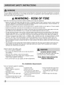
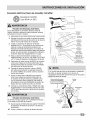
For your safety the information in this manual must be followed to minimize the risk of fire or explosion or to prevent
property damage, personal injury or loss of life. Do not store or use gasoline or other flammable vapors and liquids in
the vicinity of this or any other appliance.
A WARNING - RISK OF FIRE
Read all of the following instructions before installing and using this appliance:
- Destroy the carton and plastic bags after the dryer is unpacked. Children might use them for play. Cartons covered
with rugs, bedspreads, or plastic sheets can become airtight chambers causing suffocation. Place all materials in a
garbage container or make materials inaccessible to children.
- Clothes dryer installation and service must be performed by a qualified installer, service agency or the gas supplier.
- Install the clothes dryer according to the manufacturer's instructions and local codes.
- The electrical service to the dryer must conform with local codes and ordinances and the latest edition of the Na-
tional Electrical Code, ANSI/NFPA 70, or in Canada, the Canadian electrical code C22.1 part 1.
- The gas service to the dryer must conform with local codes and ordinances and the latest edition of the National
Fuel Gas Code ANSI Z223.1, or in Canada, CAN/ACG B149.1-2000. An individual manual shut-off valve must be
installed within 6 ft (1.83 m) of the dryer in accordance with the National Fuel Gas Code, ANSI Z223.1/NFPA 54.
- The dryer is designed under ANSI Z 21.5.1 or ANSI/UL 2158 - CAN/CSA C22.2 No. 112 (latest editions) for HOME
USE only. This dryer is not recommended for commercial applications such as restaurants, beauty salons, etc.
- Do not install a clothes dryer with flexible plastic or flexible foil venting material. Flexible venting materials are
known to collapse, be easily crushed and trap lint. These conditions will obstruct clothes dryer airflow and increase
the risk of fire.
- The instructions in this manual and all other literature included with this dryer are not meant to cover every pos-
sible condition and situation that may occur. Good safe practice and caution MUST be applied when installing,
operating and maintaining any appliance.
WHAT TO DO IF YOU SMELL GAS:
- Do not try to light any appliance.
- Do not touch any electrical switch; do not use any phone in
your building.
Clear the room, building or area of all occupants.
Immediately call your gas supplier from a neighbor's phone.
Follow the gas supplier's instructions.
If you cannot reach your gas supplier, call the fire department.
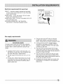
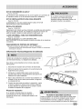
EXCESSIVE WEIGHT HAZARD
To avoid back or other injury, have more than
one person move or lift the appliance,
Save these instructionsfor
future reference.
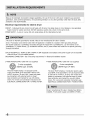
Pre-Installation Requirements
Tools and materials needed for installation:
- Adjustable pliers
- Phillips, straight, & square bit
screwd rivers
Adjustable wrench
Pipe wrench for gas supply (gas
dryer)
LP-resistant thread tape (for natu-
ral gas or LP supply, gas dryer)
- Carpenter's level
- External vent hood
- 4-inch (102 mm), rigid metal or
semi-rigid metal exhaust duct work
3-wire or 4-wire 240 volt cord kit
(electric dryer)
4 in. (102 mm) clamp
- Gas line shutoff valve (gas dryer)
- 1/2NPT union flare adapters (x2)
and flexible gas supply line (gas
dryer)
Metal foil tape (not duct tape)

Pleasereadallinstructionsbeforeusingthisdryer.
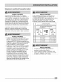
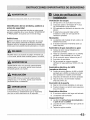
Recognize safety symbols, words and
labels
Safety items throughout this manual are labeled with
a WARNING or CAUTION based on the risk type as
described below:
Definitions
This is the safety alert symbol. It is used to alert
you to potential personal injury hazards. Obey all safety
messages that follow this symbol to avoid possible injury
or death.
DANGER indicates an imminently hazardous situation
which, if not avoided, will result in death or serious
injury,
WARNING indicates a potentially hazardous situation
which, if not avoided, could result in death or serious
CAUTION indicates a potentially hazardous situation
which, if not avoided, may result in minor or moderate
IMPORTANT indicates installation, operation or
maintenance information which is important but not
hazard-related,
Exhaust Venting
[] Free-flowing, clear of lint buildup
[] 4 inch (102 mm) rigid or semi-rigid ducting of
minimal length and turns
[] NO foil or plastic venting material
[] Approved vent hood exhausted to outdoors
Leveling
[] Dryer is level, side=to-side and front-to-back
[] Cabinet is setting solid on all corners
Gas Supply (Gas Dryer)
[] Manual shutoff valve present in supply
[] All connections sealed with approved sealer
and wrench tight
[] Conversion kit for LP system
[] Gas supply turned on
[] No leaks present at all connections -
check with soapy water, NEVERcheck with
flame
240v Electric Supply (Electric Dryer)
[] Approved NEMA 10-30R or 14-30R service
cord with all screws tight on terminal block
[] Approved strain relief installed
[] Terminal access cover installed before initial
operation
Door Reversal
[] Follow detailed instructions in this guide
[] Test hinge and latch for function
Electrical Power
[] House power turned on
[] Dryer plugged in
Final Checks
[] Installation Instructions and Use and
Care Guide read thoroughly
[] Door latches and drum tumbles when cycle
starts
[] Registration card sent in

Becauseofpotentiallyinconsistentvoltagecapabilities,theuseofthisdryerwithpowercreatedbygaspowered
generators,solarpoweredgenerators,windpoweredgeneratorsoranyothergeneratorotherthanthelocalutility
company!Snotrecommended:.............................................................................................................................................................................................................................................................................................................................................................................................................................................................................................................................................................
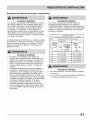
Electrical requirements for electric dryer
CIRCUIT - Individual 30 amp. branch circuit fused with 30 amp. time delay fuses or circuit breakers. Use separately
fused circuits for washer and dryer. DO NOT operate a washer and a dryer on the same circuit.
POWER SUPPLY- 3-wire or 4-wire, 240 volt, single phase, 60 Hz, Alternating Current.
This dryer is internally grounded to neutral unless it was manufactured for sale in Canada.
Only a 4-conductor cord shall be used when the appliance is installed in a location where grounding through
the neutral conductor is prohibited. Grounding through the neutral link is prohibited for: (1) new branch circuit
installations, (2) mobile homes, (3) recreational vehicles, and (4) areas where local codes do not permit grounding
OUTLET RECEPTACLE- NEMA 10-30R or NEMA 14-30R receptacle to be located so the power supply cord is accessible
when the dryer is in the installed position.
GROUNDING CONNECTION - See "Grounding requirements" in Electrical Installation section.
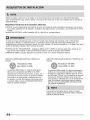
3-WIRE POWER SUPPLYCORD KIT (not supplied)
3-wire receptacle
(NEMA type 10-30R)
The dryer MUST employ a 3-conductor power
supply cord NEMA 10-30 type SRDT rated at 240
volt AC minimum, 30 amp, with 3 open end spade
lug connectors with upturned ends or closed
loop connectors and marked for use with clothes
dryers. For 3-wire cord connection instructions see
ELECTRICALCONNECTIONS FOR A 3-WIRE SYSTEM.
4-WIRE POWER SUPPLYCORD KIT (not supplied)
4-wire receptacle
(NEMA type 14-30R)
The dryer MUST employ a 4-conductor power supply
cord NEMA 14-30 type SRDT or ST (as required) rated
at 240 volt AC minimum, 30 amp, with 4 open end
spade lug connectors with upturned ends or closed
loop connectors and marked for use with clothes
dryers. For 4-wire cord connection instructions see
ELECTRICAL CONNECTIONS FOR A 4-WIRE SYSTEM.
Dryers manufactured for sale in Canada have factory-
installed, 4:w! re power Supply €ord (NEMA 14:30R):..................................

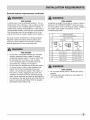
Electrical requirements for gas dryer
CIRCUIT - Individual, properly polarized and grounded
15 amp. branch circuit fused with 15 amp. time delay
fuse or circuit breaker.
POWER SUPPLY- 2-wire, with ground, 120 volt, single
phase, 60 Hz, Alternating Current.
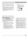
POWER SUPPLYCORD - The dryer is equipped with a 120
volt 3-wire power cord.
GROUNDING CONNECTION - See "Grounding
requirements" in Electrical Installation section.
Do not, under
any circumstances,
cut, remove,
or bypass the
grounding prong.
Powercord with
3-prong grounded plug
Gas supply requirements
1 Installation MUST conform with local codes, or in
the absence of local codes, with the National Fuel
Gas Code, ANSI Z223.1 (latest edition).
2 The gas supply line should be 1/2 inch (1.27 cm)
pipe.
3 If codes allow, flexible metal tubing may be used
to connect your dryer to the gas supply line. The
tubing MUST be constructed of stainless steel or
plastic-coated brass.
4 The gas supply line MUST have an individual
shutoff valve installed in accordance with the
B149.1, Natural Gas and Propane Installation Code.
B A 1/8 inch (0.32 cm) N.RT. plugged tapping,
accessible for test gauge connection, MUST be
installed immediately upstream of the gas supply
connection to the dryer.
6 The dryer MUST be disconnected from the gas
supply piping system during any pressure testing
of the gas supply piping system at test pressures in
excess of 1/2 psig (3.45 kPa).
7 The dryer MUST be isolated from the gas supply
piping system during any pressure testing of the
gas supply piping system at test pressures equal to
or less than 1/2 psig (3.45 kPa).
8 Connections for the gas supply must comply with
the Standard for Connectors for Gas Appliances,
ANSI Z21.24.

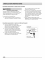
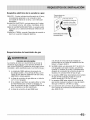
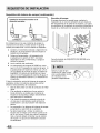
Exhaust system requirements
Use only 4 inch (102 mm) diameter (minimum) rigid
or flexible metal duct and approved vent hood which
has a swing-out damper(s) that open when the dryer
is in operation. When the dryer stops, the dampers
automatically close to prevent drafts and the entrance
of insects and rodents. To avoid restricting the outlet,
maintain a minimum of 12 inches (30.5 cm) clearance
between the vent hood and the ground or any other
obstruction.
FIRE HAZARD
Failure to follow these instructions can create excessive
drying times and fire hazards.
The following are specific requirements for proper
and safe operation of your dryer,
FIRE HAZARD
Do not install a clothes dryer with flexible plastic or
metal foil venting materials. Flexibleventing materials
are known to collapse, be easily crushed and trap lint.
These conditions will obstruct clothes dryer airflow and
increase the r!sk of fire: ..............................................................................................................................................................................................................
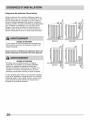
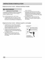
:If your present system is made up of plastic duct or
metal foil duct, replace it with a rigid or semi-rigid metal
duct. Also, ensure the present duct is free of any lint prior
to installing dryer duct.
Correct
Correct
Incorrect

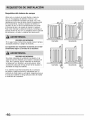
Exhaust system requirements, continued
FIRE HAZARD
A clothes dryer must be exhausted outdoors. Do not
exhaust dryer into a chimney, a wall, a ceiling, an attic,
a crawl space or any concealed space of a building. A
clothes dryer produces combustible lint. If the dryer is
not exhausted outdoors, some fine lint will be expelled
into the laundry area. An accumulation of lint in any
area of the home can create a health and fire hazard.
The dryer must be connected to an exhaust outdoors.
Regularly inspect the outdoor exhaust opening and
remove any accumulation of lint around the outdoor
exhaust opening and in the surrounding area.
FIRE HAZARD
Do not allow combustible materials (for example:
clothing, draperies/curtains, paper) to come in
contact with exhaust system. The dryer MUST NOT
be exhausted into a chimney, a wall, a ceiling,
or any concealed space of a building which can
ii
accumulate lint, resulting in a fire hazard.
Do not screen the exhaust ends of the vent system,
or use any screws, rivets or other fasteners that
extend into the duct to assemble the exhaust
system. Lint can become caught in the screen, on
the screws or rivets, clogging the duct work and
ii
creating a fire hazard as well as increasing drying
ii
times. Use an approved vent hood to terminate the
duct outdoors, and seal all joints with metal foil duct
tape. All male duct pipe fittings MUST be installed
downstream with the flow of air.
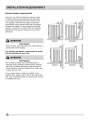
FIRE HAZARD
Exceeding the length of duct pipe or number of elbows
allowed in the "MAXIMUM LENGTH" charts can cause
an accumulation of lint in the exhaust system. Plugging
the system could create a fire hazard, as well as
z
€-
3
O-
o
E
S
go
MAXIMUM LENGTH
of 4" (102mm) Rigid Metal Duct
VENT HOOD TYPE
(Preferred)
4"
(102ram) Iouvered
64 ft. (19.5 m)
2.5"
(6.35cm)
48 ft. (14.6 m)
0
1 52 ft. (15.9 m) 40 ft. (12.2 m)
2 44 ft. (13.5 m) 32 ft. (9.8 m)
3 36 ft. (11 m) 24 ft. (7.3 m)
4 28 ft. (9.5 m) 16 ft. (4.9 m)
FIRE HAZARD
- Do not install flexible plastic or flexible foil venting
material.
If installing semi-rigid venting, do not exceed 8 ft.
(2.4 m) duct length.

Exhaust system requirements, continued
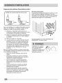
Install male fittings in correct direction"
CORRECT iNCORRECT
In installations where the exhaust system is not described
in the charts, the following method must be used to
determine if the exhaust system is acceptable:
:[ Connect an inclined or digital manometer between
the dryer and the point the exhaust connects to the
dryer.
2 Set the dryer timer and temperature to air fluff
(cool down) and start the dryer.
3 Read the measurement on the manometer.
4 The system back pressure MUST NOT be higher
than 0.75 inches of water column. If the
system back pressure is less than 0.75 inches of
water column, the system is acceptable. If the
manometer reading is higher than 0.75 inches of
water column, the system is too restrictive and the
installation is unacceptable.
Although vertical orientation of the exhaust system is
acceptable, certain extenuating circumstances could
affect the performance of the dryer:
o Only rigid metal duct work should be used.
Venting vertically through a roof may expose the
exhaust system to down drafts causing an increase
in vent restriction.
Running the exhaust system through an
uninsulated area may cause condensation and
faster accumulation of lint.
Compression or crimping of the exhaust system will
cause an increase in vent restriction.
The exhaust system should be inspected and
cleaned a minimum of every 18 months with
normal usage. The more the dryer is used, the
more often you should check the exhaust system
and vent hood for proper operation.
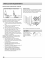
Exhaust direction
Directional exhausting can be accomplished by installing
a quick-turn 90° dryer vent elbow directly to exhaust
outlet of dryer. Dryer vent elbows are available through
your local parts distributor or hardware store.
See also Clearance Requirements on the next page.
Use of 90° quick-turn
elbow is required to meet
minimum installation
depth of free-standing

Manufactured or mobile home installation
1 Installation MUST conform to current Manufactured
Home Construction & Safety Standard, Title 24
CFR, Part 32-80 (formerly the Federal Standard
for Mobile Home Construction and Safety, Title 24,
HUD Part 280) or Standard CAN/CSAZ240 MH.
2 Dryer MUST be exhausted outside (outdoors, not
beneath the mobile home) using metal ducting
that will not support combustion. Metal ducting
must be 4 inches (10.16 cm) in diameter with no
obstructions. Rigid metal duct is preferred.
3 If dryer is exhausted through the floor and area
beneath the mobile home is enclosed, the exhaust
system MUST terminate outside the enclosure with
the termination securely fastened to the mobile
home structure.
4 Refer to previous sections in this guide for other
important exhaust venting system requirements.
5 When installing a gas dryer into a mobile home, a
provision must be made for outside make up air.
This provision is to be not less than twice the area
of the dryer exhaust outlet.
6 Installer MUST anchor this (1) dryer or (2) dryer
mounted on pedestal to the floor with approved
Mobile Home Installation Kit - P/N 137067200.
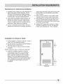
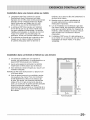
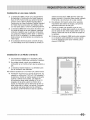
Installation in a Recess or Closet
1 A dryer installed in a bedroom, bathroom, recess or
closet, MUST be exhausted outdoors.
2 No other fuel burning appliance shall be installed in
the same closet as the gas dryer.
3 Your dryer needs the space around it for proper
ventilation.
DO NOT install your dryer in a closet with a solid door.
4 Closet door ventilation required: A minimum
of 120 square inches (774.2 cm 2) of opening,
equally divided at the top and bottom of the
door, is required. Openings should be located 3
inches (7.6 cm) from bottom and top of door.
Openings are required to be unobstructed when a
door is installed. A Iouvered door with equivalent
air openings for the full length of the door is
acceptable.
closet door

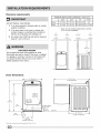
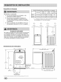
Clearance requirements
ili
DO NOT INSTALL YOUR DRYER:
1 In an area exposed to dripping water or outside
weather conditions.
2 In an area where it will come in contact with
curtains, drapes, or anything that will obstruct
the flow of combustion and ventilation air.
3 On carpet. Floor MUST be solid with a maximum
slope of 1 inch (2.54 cm).
EXPLOSION HAZARD
Do not install the dryer where gasoline or other
flammables are kept or stored. If the dryer is installed
in a garage, it must be a minimum of 18 inches (45.7
cm) above the floor. Failure to do so can result in
death, exp!os!on, fire or burns- ..............................................................................................................................................................
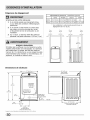
MINIMUM INSTALLATION CLEARANCES - Inches (cm)
SIDES REAR TOP FRONT
Alcove 0" (0 cm) 0" (0 cm)* 23" (58.5 cm) n/a
Closet 0" (0 cm) 0" (0 cm)* 23" (58.5 cm) 1" (2.5 cm)
* Dryer must be vented straight back to achieve
0" (0 cm) rear installation.
0" 0"
(0 cm) (0 cm)
1" 0"
(2.5 cm) (0 cm)
',', ,,,,
_..._,,'.,_..=. ...._,,,,_=.
f ;; l
Dryer Dimensions
I_ ------- 27" (68.5 cm)
"[
37"
(94 cm)
43"
1.6" fl .... , :
(109 cm)
(4 cm) ....
I"_!---- 13.50" -----_1
(34.5 cm)
to center of rear vent
centerline height
for rear vent
I (9357:'m)
50" (127 cm)
to clear open door
floorline
29" (73.5 cm)
to front of closed door
1Powersupply cord length on gas unit approximately 60 inches (t52.5 cm).

Electrical installation
The following are specific requirements for proper and
safe electrical installation of your dryer. Failure to follow
these instructions can create electrical shock and/or a fire
hazard.
ELECTRICAL SHOCK HAZARD
* This appliance MUST be properly grounded.
Electrical shock can result if the dryer is not properly
grounded. Follow the instructions in this manual for
proper grounding.
* Do not use an extension cord with this dryer. Some
extension cords are not designed to withstand the
amounts of electrical current this dryer utilizes
and can melt, creating electrical shock and/
or fire hazard. Locate the dryer within reach of
the receptacle for the length power cord to be
purchased, allowing some slack in the cord. Refer to
the pre-installation requirements in this manual for
the proper power cord to be purchased.
ELECTRICAL SHOCK HAZARD
* A U.L.-approved strain relief must be installed onto
power cord. If the strain relief is not attached, the
cord can be pulled out of the dryer and can be cut
by any movement of the cord, resulting in electrical
shock.
Do not use an aluminum wired receptacle with a
copper wired power cord and plug (or vice versa).
A chemical reaction occurs between copper and
aluminum and can cause electrical shorts. The
proper wiring and receptacle is a copper wired
power cord with a copper wired receptacle.
Dryers operating on 208 volt power supply will have
longer drying times than dryers operating on 240 volt
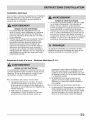
Grounding requirements - Electric dryer (USA)
ELECTRICAL SHOCK HAZARD
Improper connection of the equipment grounding
conductor can result in a risk of electrical shock. Check
with a licensed electrician if you are in doubt as to
whether the appliance is properly grounded.
ii
For a grounded, cord-connected dryer:
1 The dryer MUST be grounded. In the event of a
malfunction or breakdown, grounding will reduce
the risk of electrical shock by a path of least
resistance for electrical current.
2 After you purchase and install a 3 wire or 4 wire
power supply cord having an equipment-grounding
conductor and a grounding plug that matches you
For a
1
wiring system, the plug MUST be plugged into
an appropriate, copper wired receptacle that is
properly installed and grounded in accordance with
all local codes and ordinances. If in doubt, call a
licensed electrician.
DO NOT modify the plug you've installed on this
appliance. If it will not fit the outlet, have a proper
outlet installed by a qualified electrician.
permanently connected dryer:
The dryer MUST be connected to a grounded
metal, permanent wiring system; or an equipment
grounding conductor must be run with the circuit
conductors and connected to the equipmenb
grounding terminal or lead on the appliance.

Grounding requirements - Electric dryer (Canada)
ELECTRICAL SHOCK HAZARD
Improper connection of the equipment grounding
conductor can result in a risk of electrical shock. Check
with a licensed electrician if you are in doubt as to
whether the appliance is properly grounded.
For a grounded, cord-connected dryer:
1 The dryer MUST be grounded. In the event of a
malfunction or breakdown, grounding will reduce
the risk of electrical shock by a path of least
resistance for electrical current.
2 Since your dryer is equipped with a power supply
cord having an equipment-grounding conductor
and a grounding plug, the plug must be plugged
into an appropriate outlet that is properly installed
and grounded in accordance with all local codes
and ordinances. If in doubt, call a licensed
electrician.
3 DO NOT modify the plug provided with this
appliance. If it will not fit the outlet, have a proper
outlet installed by a qualified electrician.
Grounding requirements - Gas dryer (USA and Canada)
I The dryer is equipped with a three-prong
(grounding) plug for your protection against shock
hazard and should be plugged directly into a
properly grounded three-prong receptacle.
2 The plug must be plugged into an appropriate
outlet that is properly installed and grounded in
accordance with all local codes and ordinances. If
in doubt, call a licensed electrician.
3 DO NOT modify the plug provided with this
appliance. If it will not fit the outlet, have a proper
outlet installed by a qualified electrician.
Grounding type
wall receptacle
/- Do not, under "_
any circumstances, J
cut, remove,
or bypass the
k,_grounding prong, j

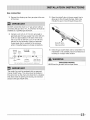
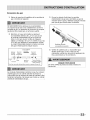
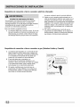
Gas connection
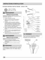
1 Remove the shipping cap from gas pipe at the rear
of the dryer,
3 Open the shutoff valve in the gas supply line to
allow gas to flow through the pipe. Wait a few
minutes for gas to move through the gas line.
DO NOT connect the dryer to LP. gas service without
converting the gas valve. An LP, conversion kit must be
installed by a qualified gas technician,
2
Connect a 1/2 inch (1.27 cm) I.D. semi-rigid or
approved pipe from gas supply line to the 3/8 inch
(0.96 cm) pipe located on the back of the dryer.
Use a 1/2 inch to 3/8 inch (1.27 cm to 0.96 cm)
reducer for the connection. Apply an approved
thread sealer that is resistant to the corrosive
action of liquefied gases on all pipe connections.
Shutoff Valve-
Open position
Manual GAS FLOW
Shutoff Flare _ Flare
Valve Union Union
:l°sed _-_ Nipple Flexible Inlet Pipe on
Open Connector Back of Dryer
All connections must be wrench-tightened
4
Check for gas system leaks with a manometer. If a
manometer is not available, test all connections by
brushing on a soapy water solution.
The supply line must be equipped with an approved
manual shutoff valve, This valve should be located in
the same room as the dryer and should be in a location
that allows ease of opening and closing, Do not block
access to the gas shutoff va!ve-..........................................................................................................................................................
EXPLOSION HAZARD
NEVER test for gas leaks with an open flame.

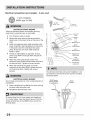
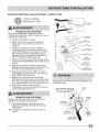
Electrical connection (non-Canada) _ 3 wire cord
3-wire receptacle
(NEMA type 10-30R)
ELECTRICA!. SHOCK HAZARD
Failure to disconnect power source before servicing
could result in personal injury or even death.
1 Turn off power supply to outlet.
2 Remove the screw securing the terminal block
access cover in the lower corner on the back of the
dryer.
3 Install a UUapproved strain relief according to the
power cord/strain relief manufacturer's instructions
in the power cord entry hole below the access
panel. At this time, the strain relief should be
loosely in place.
4 Thread an UNPLUGGED, UUapproved, 30 amp.
power cord, NEMA 10-30 type SRDT, through the
strain relief.
5 Attach the power cord neutral (center wire)
conductor to the SILVER colored center terminal on
the terminal block. Tighten the screw securely.
6 Attach the remaining two power cord outer
conductors to the outer, BRASScolored terminals
on the terminal block. Tighten both screws
securely.
ELECTR:ICAL SHOCK HAZARD
Do not make a sharp bend or crimp wiring/conductor at
connections.
7 Follow manufacturer's guidelines for firmly securing
the strain relief and power cord.
8 Reinstall the terminal block cover.
If moving dryer from a 4-wire system and installing it
in a 3-wire system, move the internal ground from the
center terminal back to the GREEN screw next to the
term!hal block:.................................................................................................................................................................................................................................................................
............. _ Install
UL-approved
strain relief here
Terminal screw
recovery slot
If a terminal screw falls during cord installation, it can
be retrieved in the terminal screw recovery slot below
the access panel.
DO NOT remove
internal ground in
a 3-wire system!!
Neutral
,terminal

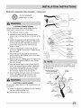
Electrical connection (non-Canada) - 4 wire cord
4-wire receptacle
(NEMA type 14-30R)
-- Neutral
(WHITE wire)
ELECTRICAL SHOCK HAZARD
Failure to disconnect power source before servicing
could result in personal injury or even death.
1 Turn off power supply to outlet.
2 Remove the screw securing the terminal block
access cover in the lower corner on the back of the
dryer.
3 Install a UL-approved strain relief according to the
power cord/strain relief manufacturer's instructions
in the power cord entry hole below the access
panel. At this time, the strain relief should be
loosely in place.
4 Thread an UNPLUGGED, UL-approved, 30 amp.
power cord, NEMA 14-30 type ST or SRDT,through
the strain relief.
5 Disconnect the internal (WHITE) dryer harness
ground wire from the (GREEN) ground screw next
to the terminal block.
6 Attach the ground (GREEN) power cord wire to the
cabinet with the ground (GREEN) screw. Tighten
the screw securely.
7 Move the internal dryer harness ground (WHITE)
wire to the terminal block and attach it along with
the neutral (WHITE) power cord wire conductor
to the center, SILVER colored terminal on the
terminal block. Tighten the screw securely.
8 Attach the RED and BLACKpower cord conductors
to the outer, BRASScolored terminals on the
terminal block. Tighten both screws securely.
ELECTRICAL SHOCK HAZARD
Do not make a sharp bend or crimp wiring/conductor at
connections,
9 Follow manufacturer's guidelines for firmly securing
the strain relief and power cord.
10 Reinstall the terminal block cover.
_ _ Access cover
_jj screw
___S T_lm icrka'
Line 2
__z'-L_- _ (BRASSterminal)
_ Line 1
..... (BRASSterminal)
_ internal ground
(GREEN screw)
Terminal screw
recovery slot
If a terminal screw falls during cord installation, it can
be retrieved in the terminal screw recovery slot below
Move internal ground (WHITE)
wire to neutral (SILVER)
terminal for 4-wire system.
GREEN
ground screw
GREEN
ground wir_
BLACKor
REDpower wire
Neutral
terminal
WHITE
neutral wire
BLACK
or RED
power wire

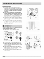
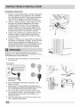
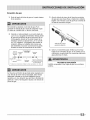
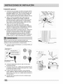
General installation
1 Connect the exhaust duct to the outside exhaust
system (see pages 6 through 8). Use of a 4" (102 mm)
clamp (item A) is recommended to connect the dryer to
the exhaust vent system. Use metal foil tape to seal all
other joints.
2 Use a carpenter's level to level your dryer front-to-
back and side-to-side. For front-to-back leveling, place
bottom edge of the level on the seam between the top
panel and side panel. For side-to-side leveling place the
bottom side of the level flush to the side panel.
3 Use adjustable pliers to adjust the leveling legs so the
dryer is level front-to-rear and side-to-side, and stable
corner-to-comer.
4 Press down on alternate corners and sides and feel for
the slightest movement. Adjust the appropriate leg(s)
so the dryer sits solidly on the floor on ALL four legs.
Keep the leveling leg extension at a minimum for best
performance of the dryer.
Be sure the power is off at a circuit breaker/fuse box before
PlUgging the power cord into an outlet: ................
5 Plug the power cord into a grounded outlet.
3=pron
6
7
8
9
Turn on the power at the circuit breaker/fuse box.
Read the Use & Care Guide provided with the dryer. It
contains valuable and helpful information that will save
you time and money.
If you have any questions during initial operation,
please review the "Avoid Service Checklist" in your Use
& Care Guide before calling for service.
Place these instructions in a location near the dryer for
future reference.
iii{i
...Jv
c
lower
ra

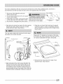
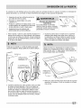
Yourdryerisdesignedsothedoorswingmaybereversedatanytimewithoutadditionalparts.Conversionis
accomplishedbytransferringhingesanddoorstriketotheoppositesidesofthecabinet.
1 Besureyouhaveadequateswingarea
beforereversingdoor.
2 Youwillneedascrewdriverwitha#2square
bitandapairofpliers.
3 Protectfiatworksurface,suchastopofdryer
orfloorneardryer,withasoftclothortowel.
4 Besuredryerisunpluggedfrompowersource!
ELECTRICAL SHOCK HAZARD
Failure to disconnect power source
before servicing could result in
...........personal inJu_ or even death:............................................................
Tools needed:
Screwdriver with #2 Adjustable
square bit pliers
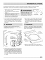
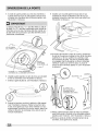
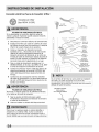
Open door and remove four plugs in the door opening
opposite the hinges. Retain all parts for use later,
unless otherwise noted. (Figure below)
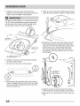
Place door on a towel (front side down) to prevent
scratches to paint or window (if equipped). Remove
all four remaining long hinge screws on edge of door.
(Figure below)
Youmayneeda plasticknifeto helppulloutthe plugs,
Be careful not to scratch the paint.
ii
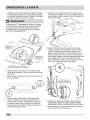
o
"D" STAMPED ON
DOOR SIDE OF
HINGE INTERIOR
Begin removing the four short screws that attach the
hinge to the front panel. (Figure Above) Start by only
removing one screw per hinge. Then only loosen the
two remaining screws while firmly holding the door to
prevent damage to hinge, front panel or door. After the
remaining screws are loosened, continue to remove all.
Observe the "D" stamped on the interior of the hinge
on the door side. When reversed to the other side, this
"D" must be visible after the hinge is remounted.
DOOR EDGE
SCREWS (x 4)
DOOR HINGE
SCREWS (x 4)
4 Remove the four long screws from edge of door
opposite hinges. (Figure above)

5 Installfourlongscrewssecuringhingetodoor
assemblyinthenewlocation,takenotetoplaceeach
hingeincorrectorientation.(Figurebelow)
9 Install new striker (included in literature bag) into hole
square plug was previously installed in. (Figure below)
The plate with the stamped "D" is mounted to the door.
The "D" must be visible after the hinge is remounted
and the spine of the hinge should be oriented toward
the front side of the door for correct operation.
DOOR EDGE
SCREWS (x 4)
DOOR HINGE
SCREWS (x 4)
10 Grasping firmly the top of the door, position the door
near the door opening and align the top hinge hole
to the top hole in the front panel door opening. Once
the first short screw is started, attach the second
short screw to the lower hinge. Once both screws
are tightened, install the remaining two short screws.
(Figure below)
"D" STAMPED ON DOOR SIDE
OF HINGE INTERIOR
6 Install four long screws into holes that had secured
the hinges. (Figure above)
7 Remove striker and discard. (Figure below)
8 Remove square plug opposite striker. (Figure above)
If plug is damaged during removal, discard and install
new plug (included in literature bag) into hole striker
was just removed from.
HOLE PLUGS (x 4)
"D" STAMPED ON
DOOR SIDE OF
HINGE INTERIOR
)
o
o
11 Install four plugs into the front panel door opening
where hinges were originally installed. (Figure above)
12 Close the door and test operation of hinge, strike and
latch.

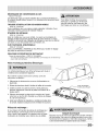
LP CONVERSION KIT
P/N PCK4200
Gas dryers intended for use in a location supplied with LP must use a
conversion kit prior to installation.
MOBILE HOME INSTALLATION KIT
P/N 137067200
Installation in a mobile home requires the use of a MOBILE HOME
INSTALLATION KIT.
Failure to use accessories manufactured by
approved by) the manufacturer could
result in personal injury, properly damage
or damage to the dryer.
DRYING RACK
P/N 137O673OO
Depending on the model you purchased, a drying rack may have been
included in the initial purchase of your dryer. If your model did not include
a drying rack or you desire another drying rack, you may order one.
UNIVERSAL APPLIANCE WRENCH
P/N 137019200
A UNIVERSAL APPLIANCE WRENCH is available to aid in dryer or washer
feet adjustment.
TOUCH UP PAINT PENS*
Classic White Touch Up Pen - P/N 5304468812
*Other colors may be available. Contact the source where you purchased your dryer.
///
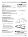
Technical Sheet/Wiring Diagram:
A wiring diagram and technical data sheet are located
To remove the console faceplate follow the directions
below:
1. Disconnect dryer from electrical source.
2. Remove the hole plugs on the back of the console
housing.
3. Insert a small, straight blade screw drive to gently pry
downward on each faceplate retaining tab.
4. Gently lay the console faceplate forward without
pulling wires to access technical/wiring diagram.
5. When finished with repair, return sheet inside console,
snap faceplate to console housing and reinstall hole
plugs.
TECH DATA SHEET/
WIRING DIAGRAM
Replacement parts:
If replacements parts are needed for your dryer, contact
the source where you purchased your dryer or refer to
your Use and Care Guide for more information. ELECTRICAL SHOCK HAZARD
Label all wires prior to disconnection when servicing
controls.Wiring errors can cause improper and dangerous
operation. Verify proper operation after servicing.

La page est en cours de chargement...
La page est en cours de chargement...
La page est en cours de chargement...
La page est en cours de chargement...
La page est en cours de chargement...
La page est en cours de chargement...
La page est en cours de chargement...
La page est en cours de chargement...
La page est en cours de chargement...
La page est en cours de chargement...
La page est en cours de chargement...
La page est en cours de chargement...
La page est en cours de chargement...
La page est en cours de chargement...
La page est en cours de chargement...
La page est en cours de chargement...
La page est en cours de chargement...
La page est en cours de chargement...
La page est en cours de chargement...
La page est en cours de chargement...
La page est en cours de chargement...
La page est en cours de chargement...
La page est en cours de chargement...
La page est en cours de chargement...
La page est en cours de chargement...
La page est en cours de chargement...
La page est en cours de chargement...
La page est en cours de chargement...
La page est en cours de chargement...
La page est en cours de chargement...
La page est en cours de chargement...
La page est en cours de chargement...
La page est en cours de chargement...
La page est en cours de chargement...
La page est en cours de chargement...
La page est en cours de chargement...
La page est en cours de chargement...
La page est en cours de chargement...
La page est en cours de chargement...
-
 1
1
-
 2
2
-
 3
3
-
 4
4
-
 5
5
-
 6
6
-
 7
7
-
 8
8
-
 9
9
-
 10
10
-
 11
11
-
 12
12
-
 13
13
-
 14
14
-
 15
15
-
 16
16
-
 17
17
-
 18
18
-
 19
19
-
 20
20
-
 21
21
-
 22
22
-
 23
23
-
 24
24
-
 25
25
-
 26
26
-
 27
27
-
 28
28
-
 29
29
-
 30
30
-
 31
31
-
 32
32
-
 33
33
-
 34
34
-
 35
35
-
 36
36
-
 37
37
-
 38
38
-
 39
39
-
 40
40
-
 41
41
-
 42
42
-
 43
43
-
 44
44
-
 45
45
-
 46
46
-
 47
47
-
 48
48
-
 49
49
-
 50
50
-
 51
51
-
 52
52
-
 53
53
-
 54
54
-
 55
55
-
 56
56
-
 57
57
-
 58
58
-
 59
59


Frigidaire FARG1011MW2 Guide d'installation
- Catégorie
- Sèche-linge
- Taper
- Guide d'installation