La page est en cours de chargement...

Model Numbers: QSGRJ-6E, QSGRJ-8E, QSGRJ-16E
QSGR-6E, QSGR-8E, QSGR-16E
120 V~
50/60 Hz
220 - 240 V~
50/60 Hz
Unit Capacity (watts) 2000 W 3000 W
MLV 2000 VA
1600 W
3000 VA
2400 W
Zone Capacity (watts) 25 – 800 W 40 – 1200 W
MLV 25 – 800 VA
25 – 600 W
40 – 1200 VA
40 – 960 W
See page 6 for EcoSystem bus ratings;
see page 7 for IEC PELV/NEC® Class 2 ratings.
For California residents only:
The batteries in these devices contain Perchlorate Material –
special handling may apply.
For more information visit
www.dtsc.ca.gov/hazardouswaste/perchlorate
LUTRON
with EcoSystem
Control Unit
Quick Installation and
Operation Guide
®
Please Read
Contents
Features and Functions of the GRAFIK Eye QS Control Unit ....2
Wiring the GRAFIK Eye QS Control Unit
Overview of Line Voltage/Mains and EcoSystem Wiring .......... 3
Line Voltage Wiring Details.................................. 4
EcoSystem Bus Wiring Details...............................6
Overview of IEC PELV/NEC® Class 2 Wiring .................... 7
QS Link Control Wiring Details............................... 8
Power Group Wiring Example ............................... 9
Completing Installation of the GRAFIK Eye QS Control Unit ....10
Programming Mode
Entering and Exiting Programming Mode ..................... 11
Navigating Menus in Programming Mode ..................... 11
Wireless Mode.......................................12
FCC Information ......................................... 12
Zone Setup
Assigning Load Types..................................... 13
Assigning Non-Dim Load Type.............................. 13
Setting Load Types.......................................14
EcoSystem Setup
Building the System ...................................... 15
Assigning/Unassigning an EcoSystem Device to a Zone......... 16
Scene Setup
Setting Zone Levels, Fade Rates, and Shade Group Actions ..... 17
Sensor Setup .......................................18
Scene Mode ............................................ 19
Configuring Occupancy Sensor Settings (optional) ............. 20
Pico Wireless Control Setup:
Associating with a GRAFIK Eye QS Wireless Control Unit........21
Troubleshooting .....................................22
Troubleshooting: EcoSystem Functions ..................23
Warranty ...........................................24
Contact Information ..................................24
For additional features and advanced functions, see the
complete installation and operation guide at www.lutron.com/qs
The GRAFIK Eye QS with EcoSystem control unit allows for
control of both lights and shades, without interfaces, using a
single control unit. Features include pushbutton scene recall,
info screen that displays energy savings and status, IR receiver,
astronomic timeclock, contact closure input, and engravable
backlit buttons that are easy to find and operate. The built-in
EcoSystem bus link can control up to 64 EcoSystem devices.
English
Español
Français

OK
12
3
4
5
6910
11 12
13
14
7
815 16
9-16
1-8
®
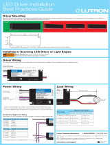
Info screen
Displays status or
programming functions
Scene buttons
With integral scene
indicator LEDs
Optional Shade
button groups
Preset and raise/lower
buttons with integral LEDs
(maximum of 3 button
groups)
Zone numbers
Zone raise/lower buttons
Zone LEDs display current
lighting zone levels
Timeclock button
Displays current
timeclock info
OK button
Used for programming
Infrared receiver
For handheld remote use
Master buttons
Temporarily raise and lower
lighting levels on unit
USB type mini B
For programming via PC
{
Hinged faceplate
Hinged faceplate
Features and Functions of the GRAFIK Eye QS with EcoSystem Control Unit
Note: Zones 1, 2, and 3 are
integral line voltage dimming
zones that can control line
voltage loads. Remaining zones
are EcoSystem zones only.
Zones 1, 2, and 3 can be either
EcoSystem zones or line voltage
zones (no zone can be both)
Page button
Switches between displaying
zones 1 to 8 and 9 to 16 on
16-zone unit
Note: 6-zone control unit will show only zones 1 through 6.
For additional information, see the complete installation and operation guide at www.lutron.com/qs
GRAFIK Eye QS with EcoSystem Control Unit Quick Installation and Operation Guide 2

®
For additional information, see the complete installation and operation guide at www.lutron.com/qs
GRAFIK Eye QS with EcoSystem Control Unit Quick Installation and Operation Guide 3
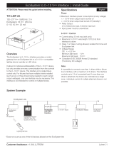
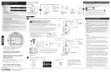
Wiring the GRAFIK Eye QS with EcoSystem Control Unit:
Overview of Line Voltage/Mains and EcoSystem Wiring
12 AWG (4.0 mm
2
)
each terminal
120 V~
or
220 - 240 V~
Distribution
Panel
Line Voltage/Mains
Cables and Load Wiring
E2
E1
E2
E1
To additional
EcoSystem devices
EcoSystem Bus Wiring
(See the bus wiring details section for
complete specification)
Two 16 AWG (1.5 mm
2
)
each terminal
EcoSystem devices: LED
drivers, interfaces, or ballasts
Two E1 and two E2 connections are
provided for ease of wiring, and to
provide two connecting points; there is
only one EcoSystem link on the unit.
Note: Ballasts and other EcoSystem
devices must NOT obtain power from a
line voltage output on the GRAFIK Eye
QS with EcoSystem control unit.
Distribution
Panel
L
N
L
N
Dimmable LED bulb*
Load controlled
by power module
or interface
Terminal labels:
L: Hot/Live
N: Neutral
: Ground
1, 2, 3: Dimmed/Switched
line voltage outputs
Power module
or interface
* For a complete list of approved dimmable LEDs
please call 1.800.523.9466 or visit
www.lutron.com/dimcflled

®
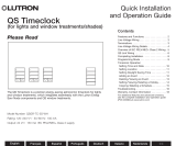
Wiring the GRAFIK Eye QS with EcoSystem Control Unit:
Line Voltage Wiring Details
• Useproperlycertifiedcableforallline
voltage/mains cables.
• Propershort-circuitandoverload
protection must be provided at the
distribution panel. You can use up to a
20 A circuit breaker for your installation.
• Installinaccordancewithalllocaland
national electrical codes.
• IECPELV/NEC® Class 2 terminals may
be temporarily unplugged for ease of IR,
occupancy sensor, and control wiring.
• Notice: Risk of damage to unit. Do not
connect line voltage/mains cable to IEC
PELV/NEC® Class 2 terminals.
Step 1: Install wallbox. Mount a 3½ in
(89 mm) deep 4-gang U.S. wallbox on a
dry, flat indoor surface that is accessible
and allows for system programming and
operation. Allow at least 4½ in (110 mm)
clearance above and below the faceplate
to ensure proper heat dissipation. Allow
1 in (25 mm) for faceplate overhang on
all sides.
Note: 4-gang wallbox available from
Lutron;P/N241400.
Step 2: Test load wiring.
• TurnpowerOFFatthecircuitbreakeror
fuse box.
• Connectastandardlightswitchbetween
the live lead and load wire to test the
circuit.
• TurnpowerONandcheckforshortor
open circuits. If load does not operate,
the circuit is open. If the circuit breaker
trips (fuse blows or opens), a load short
may exist. Correct short or open circuits
and test again.
`
Step 3: Check control unit wiring.
• Earth/ground terminal connection must
be made as shown in line voltage wiring
diagrams.
• Do not mix different load types on the
same zone.
• Follow all local and national electrical
codes when installing IECPELV/NEC®
wiring with line voltage/mains wiring.
WARNING! Shock hazard. May
result in serious injury or death.
Always turn off circuit breaker or
remove main fuse from power line
before doing any work. Before
connecting the loads to the
GRAFIK Eye QS with EcoSystem
control unit, test the loads for
short-circuits.
(continued on next page)
Neutral
Hot/Live
Switch
Load
LUTRON
LUTRON
Faceplate overhangs
wallbox on all sides;
allow 1 in (25 mm)
4` in
(110 mm)
For additional information, see the complete installation and operation guide at www.lutron.com/qs
GRAFIK Eye QS with EcoSystem Control Unit Quick Installation and Operation Guide 4

®
For additional information, see the complete installation and operation guide at www.lutron.com/qs
GRAFIK Eye QS with EcoSystem Control Unit Quick Installation and Operation Guide 5
Wiring the GRAFIK Eye QS with EcoSystem Control Unit:
Line Voltage Wiring Details (continued)
Step 4: Connect line voltage and loads
to control unit.
• Strip9 in (8 mm) of insulation off the line
voltage/mains cables in the wallbox.
• Connectthelinevoltage/mains,ground,
and load wires to the appropriate
terminals on the back of the control unit.
L: Hot/Live
N:Neutral
: Ground
Terminals 1, 2, 3: Dimmed/Switched
line voltage outputs
9 in
(8 mm)
The recommended installation torque is
5.0 in∙lb(0.6N∙m) for line voltage/mains
connections and 5.0 in∙lb(0.6N∙m) for
the earth/ground connection.
Note: See the zone setup section for a
list of compatible load types and
instructions for programming the
GRAFIK Eye QS with EcoSystem
control unit to properly recognize
them.
Notice: Risk of damage to unit. GRAFIK Eye QS with EcoSystem control units must
be in stalled by a qual i fied electrician in accordance with all applica ble reg u la tions
and building codes. Im prop er wiring can result in dam age to control units or oth er
equipment.
Note: To avoid over heat ing and pos si ble damage to equipment, do not install control
units to dim re cep ta cles, mo tor-op erated ap pli ances, or flu o res cent lighting not
equipped with Lutron Hi-lume, Eco-10, Tu-Wire, EcoSystem electron ic dim ming
ballasts, or other EcoSystem devices approved for your location. In dimmed mag net ic
low-voltage cir cuits, you can pre vent trans former overheating and failure by avoid ing
excessively high cur rent flow. Do not op erate control units with any lamps re moved
or burned out; re place any burned out lamps imme di ate ly; use only transform ers that
in cor po rate ther mal pro tection or fused pri ma ry wind ings. Control units are de signed for
res i den tial and commercial use, for indoor use only.

®
EcoSystem bus wiring may be considered
NEC®Class1orIECPELV/NEC® Class
2.
• NEC® Class 1: EcoSystem bus wiring
may be run in the same conduit as mains
voltage wiring to fixtures.
• IECPELV/NEC® Class 2: EcoSystem bus
wiring must be separated from all mains
and NEC® Class 1 wiring.
• Consult applicable national and local
codes for compliance.
• Lutronrecommendsusingtwodifferent
colors for E1 and E2 (EcoSystem bus)
wires. This will prevent wiring mistakes
in junction boxes where several different
EcoSystem bus wires combine. Use
the following instructions for wiring the
EcoSystem bus.
• EachEcoSystem link can have only 1
GRAFIK Eye QS with EcoSystem control
unitconnectedtoit.Noadditional
EcoSystem bus supplies can be on the
link.
• Upto64EcoSystem devices can be
connected to the EcoSystem link.
• Nootherdevicesmaybeconnectedto
the EcoSystem link.
WARNING! Shock hazard. May
result in serious injury or death.
Do not wire live. Interrupt power
via circuit breaker before wiring
and servicing the EcoSystem bus
supply.
Step 1: Use the wire size chart at right to
determine which wire size to use based
on the length of the EcoSystem bus.
Step 2: Wire the EcoSystem bus from
terminal E1 and terminal E2 to all
EcoSystem devices.
Step 3: If wiring the EcoSystem bus as
IECPELV/NEC® Class 2, maintain proper
separation from mains and NEC® Class 1
wiring.
Step 4: Turn on circuit breaker to
energize.
EcoSystem Bus
18 V- 250 mA
Wiring the GRAFIK Eye QS with EcoSystem Control Unit:
EcoSystem Bus Wiring Details
Wiring Size and Bus Length
EcoSystem bus wires E1 and E2 are not
polarity sensitive. EcoSystem bus length
is limited by the wire gauge used for E1
and E2 as follows:
Wire Gauge Maximum EcoSystem
Bus Length
12 AWG
(4.0 mm
2
)
2200 ft (671 m)
14 AWG
(2.5 mm
2
)
1400 ft (427 m)
16 AWG
(1.5 mm
2
)
900 ft (275 m)
18 AWG
(1.0 mm
2
)
570 ft (175 m)
Note: Some EcoSystem devices
(ballasts, drivers, and interfaces)
accept connections to daylight
sensors and occupancy sensors.
For instructions on installing and
operating these devices, refer to
their individual instruction sheets.
EcoSystem bus wiring cables (16 AWG/
1.5 mm
2
) are available from Lutron, part
numbers C-CBL-216-GR-1 (non-plenum)
and C-PCBL-216-CL-1 (plenum).
For additional information, see the complete installation and operation guide at www.lutron.com/qs
GRAFIK Eye QS with EcoSystem Control Unit Quick Installation and Operation Guide 6

Contact Closure Input Wiring
24 V- 50 mA
For settings, see the full installation
and operation guide at
www.lutron.com/qs.
®
12
ABC
N H123456
1234
1234
12
ABC
123456LN
1234
12
ABC
123456LN
Note: Use appropriate wire connecting devices
as specified by local codes.
Example:
Occupancy sensor
(maximum 1)
1: COM
2: 24 V-*
3: MUX
4: MUX
QS Link Control Wiring
24 V- 100 mA
Wiring the GRAFIK Eye QS with EcoSystem Control Unit:
Overview of IEC PELV/NEC® Class 2 Wiring
IR Wiring
From external
IR connection
(by others)
18 AWG (1.0 mm
2
)
each terminal
18 AWG (1.0 mm
2
)
each terminal
1: IR DATA
2: IR COM
A: CCI SIG
B: 24 V-
C: CCI COM
To control stations,
shades, or other
GRAFIK Eye QS
control units
Data (terminals 3 and 4):
Twisted, shielded pair 22 AWG (0.5 mm
2
)
each terminal
Common and power (terminals 1 and 2):
Two 18 AWG (1.0 mm
2
) each terminal (for link <500 ft/153 m)
Two 12 AWG (4.0 mm
2
) each terminal (for link 500-2000 ft/153-610 m)
* Do not connect terminal 2
between any GRAFIK Eye QS
control unit and any other power
supply, including another GRAFIK
Eye QS control unit.
See “Power Group Wiring” for a
detailed wiring example.
1234
12
ABC
123456LN
Example:
Emergency lighting interface (maximum 1)
Note: The GRAFIK Eye QS control unit must
bepoweredbyaNormal/Emergency
distribution panel for proper ELI
operation. Refer to the LUT-ELI-3PH
Installation Guide for the complete
wiring diagram.
A: CCI SIG
B: 24 V-
C: CCI COM
LUT-ELI-3PH
Signal
+V Input
Circuit Common
For additional information, see the complete installation and operation guide at www.lutron.com/qs
GRAFIK Eye QS with EcoSystem Control Unit Quick Installation and Operation Guide 7

• SystemcommunicationusesIECPELV/NEC®
Class 2 wiring.
• Followalllocalandnationalelectricalcodeswhen
installingIECPELV/NEC® Class 2 wiring with line
voltage/mains wiring.
• Eachterminalacceptsuptotwo18AWG(1.0mm
2
)
wires.
• Totallengthofcontrollinkmustnotexceed
2000 ft (610 m).
• Makeallconnectionsinthecontrolunit’swallbox.
• WiringcanbeT-tappedordaisy-chained.
• IECPELV/NEC® Class 2 24 V- 150 mA.
System Limits
The QS wired communication link is limited to 100
devices or 100 zones.
The GRAFIK Eye QS control unit supplies 3 Power
Draw Units (PDUs) on the QS link. Refer to the
QS Link Power Draw Units specification submittal
(LutronPN369405)formoreinformationconcerning
Power Draw Units.
®
Wiring the GRAFIK Eye QS with EcoSystem Control Unit:
QS Link Control Wiring Details
QS smart
power
panel
LUTRON
LUTRON
LUTRON
LUTRONLUTRON
LUTRON
LUTRON
LUTRON
LUTRON
LUTRON
LUTRON
LUTRON
T-Tap Wiring Example
GRAFIK Eye QS
with EcoSystem
control unit
Sivoia QS
shade/drape
seeTouch QS
wallstation
To EcoSystem link 1
To EcoSystem
link 2
LUTRON
LUTRON
LUTRON
LUTRONLUTRON
LUTRON
LUTRON
LUTRON
LUTRON
LUTRON
LUTRON
LUTRON
GRAFIK Eye
QS with
EcoSystem
control unit
Sivoia
QS
shade/
drape
seeTouch QS
wallstations
Daisy-Chain Wiring Example
QS smart
power panel
To EcoSystem link 2To EcoSystem link 1
For additional information, see the complete installation and operation guide at www.lutron.com/qs
GRAFIK Eye QS with EcoSystem Control Unit Quick Installation and Operation Guide 8
Wire Sizes (check compatibility in your area)
QS Link Wiring Length Wire Gauge Lutron Cable Part Number
Less than 500 ft (153 m) Power (terminals 1 and 2)
1 pair 18 AWG (1.0 mm
2
) GRX-CBL-346S (non-plenum)
GRX-PCBL-346S (plenum)
Data (terminals 3 and 4)
1 twisted, shielded pair 22 AWG (0.5 mm
2
)
500 to 2000 ft
(153 to 610 m)
Power (terminals 1 and 2)
1 pair 12 AWG (4.0 mm
2
) GRX-CBL-46L (non-plenum)
GRX-PCBL-46L (plenum)
Data (terminals 3 and 4)
1 twisted, shielded pair 22 AWG (0.5 mm
2
)

Wiring the GRAFIK Eye QS with EcoSystem Control Unit: Power Group Wiring Example
®
For additional information, see the complete installation and operation guide at www.lutron.com/qs
GRAFIK Eye QS with EcoSystem Control Unit Quick Installation and Operation Guide 9
On the QS link, there are devices that supply power and devices that consume power. Each device has a specific number of Power
Draw Units (PDUs) it either supplies or consumes. A Power Group consists of one device that supplies power and one or more
devices that consume power; each Power Group may have only one power-supplying device. Refer to the QS Link Power Draw Units
specificationsubmittal(LutronPN369405)formoreinformationconcerningPDUs.
Within Power Groups on the QS link, connect all 4 terminals (1, 2, 3, and 4), shown by the letter A in the diagram. Between devices on
theQSlinkthatsupplypower,connectonlyterminals1,3,and4(NOTterminal2),shownbytheletterBonthediagram.
Wiring can be T-tapped or daisy-chained.
LUTRON
LUTRON LUTRON
LUTRON
LUTRON
LUTRON
Power Group 1
Power Group 2
Power Group 3
A
A
B
B
(Do not connect
terminal 2: 24 V-)
(Do not connect
terminal 2: 24 V-)
GRAFIK Eye QS
control unit
Supplies PDUs
QS Power Supply
Supplies PDUs
Energi Savr Node
unit Supplies PDUs
Control Interfaces
Consume PDUs
Control Interfaces
Consume PDUs
Wallstations
Consume PDUs
Wallstations
Consume PDUs
Wallstations
Consume PDUs
QS Sensor Module with
Occupancy Sensor
Consumes PDUs
Connect all 4 terminals within a
power group:
1: Common
2: 24 V-
3 and 4: Data
Connect only 3 terminals
between power groups:
1: Common
3 and 4: Data
Do not connect
Terminal 2: 24 V-
A
B
Quantum panel
Supplies PDUs
B
A

®
Completing Installation of the GRAFIK Eye QS Control Unit
1. Mount the control unit in the wallbox as
shown using the four screws pro vid ed.
Note: Follow all local and national
electrical codes when installing IEC
PELV/NEC® Class 2 wiring with line
voltage/mains wiring.
2. Verify installation:
• Restore power.
• Press the top scene button. The LED will
light.
• Press the zone raise and lower buttons.
Make sure the control unit is dimming all
connected loads.
3. Apply the protective overlay to the control
unit.
Note: When tightening mounting
screws, make sure that the hinged
cover and faceplate will open fully,
as shown.
Wall
7.9 in
(200 mm)
3.5 in
(87 mm)
3.75 in
(95 mm)
Protective overlay
(apply after installation)
For additional information, see the complete installation and operation guide at www.lutron.com/qs
GRAFIK Eye QS with EcoSystem Control Unit Quick Installation and Operation Guide 10

Entering and Exiting Programming Mode
Entering programming mode:
Press and hold the top and bottom scene
buttons simultaneously for 3 seconds. The
LEDs in the scene buttons will scroll from
top to bottom, confirming that you are in
programming mode, and the info screen will
display the main menu.
Exiting programming mode:
Press and hold the top and bottom scene
buttons simultaneously for 3 seconds. The
info screen will go to Scene 1.
Navigating Menus in Programming Mode
Master Buttons
The Master buttons allow you to move through the menu
choices. The current choice is highlighted on the info screen.
OK Button
The OK button chooses the current highlighted menu choice.
This will either take you to the next menu or accept a setting you
haveselected.WhenthescreendisplaysaYes/Noquestion,the
OK button is “Yes”.
Timeclock Button
The timeclock button functions as a “back” button during
programming mode. Pressing the timeclock button takes you
back one step in the current menu. Pressing it repeatedly
will eventually return you to the main menu, but will not exit
programmingmode.WhenthescreendisplaysaYes/No
question,theTimeclockbuttonis“No”.
®
Programming Mode
OK
12
3
4
5
6910
11 12
13
14
7
815
16
9-16
1-8
Press and hold the top and
bottom buttons for 3 seconds
to enter or exit programming
mode
Master buttons
OK button
Timeclock (back) button
Main menu
Scene setup
Timeclock
Scene 1
Fade time
3 seconds
For additional information, see the complete installation and operation guide at www.lutron.com/qs
GRAFIK Eye QS with EcoSystem Control Unit Quick Installation and Operation Guide 11

®
For additional information, see the complete installation and operation guide at www.lutron.com/qs
GRAFIK Eye QS with EcoSystem Control Unit Quick Installation and Operation Guide 12
Wireless Mode
Many models of the GRAFIK Eye QS control unit support wireless communication with
other Lutron products. This feature allows for easy integration of wireless sensors,
keypads, remotes, and shades for single-room wireless applications
Units supporting wireless communication are labeled “GRAFIK Eye QS Wireless” on the
front label of the unit.
The wireless feature of the GRAFIK Eye QS Wireless control unit has three (3) modes of
operation.
• Disabled: Use for wired-only systems.
• Enabled: The GRAFIK Eye QS Wireless control unit will respond to any programming
commands from nearby Lutron QS wireless (and compatible) products.
• Ignore Programming (default): The GRAFIK Eye QS Wireless control unit will only
respond to normal operation commands from wireless devices associated while in
Enabled mode.
Changing the wireless mode of the GRAFIK Eye QS Wireless control unit:
1. Enter programming mode.
2. Use the Master buttons to highlight “Wireless Mode” and press
the OK button to accept.
3. Use the Master buttons to highlight the desired wireless mode,
and press the OK button to accept.
4. The info screen will display a confirming “Saved” message.
5. Exit programming mode.
Note: The wireless signal has a range of 30 ft (9 m) through
standard construction or 60 ft (18 m) line of sight.
Wireless Mode
Enabled
Saved
Saved
Main menu
Shade labels
Wireless Mode
FCC Information
Changes or modifications not expressly approved
by Lutron Electronics Co. could void the user’s
authority to operate this equipment.
Note: This equipment has been tested and
found to comply with the limits for a Class B
digital device, pursuant to Part 15 of the FCC
rules. Operation is subject to the following: (1)
This device may not cause harmful interference,
and (2) this device must accept any interference
received, including interference that may cause
undesired operation.
These limits are designed to provide
reasonable protection against harmful interference
in a residential and commercial installation. This
equipment generates, uses, and can radiate
radio frequency energy and, if not installed and
used in accordance with the instructions, may
cause harmful interference to radio or television
reception. However, there is no guarantee
that interference will not occur in a particular
installation. If this equipment does cause harmful
interference to radio or television reception, which
can be determined by turning the equipment off
and on, the user is encouraged to try to correct
the interference by one or more of the following
measures:
• Reorientorrelocatethereceivingantenna.
• Increasetheseparationbetweentheequipment
and receiver.
• Connecttheequipmentintoanoutletona
circuit different from that to which the receiver is
connected.
• Consultthedealeroranexperiencedradio/TV
technician for help.
OK
12
3
4
5
6910
11 12
13
14
7
815
16
9-16
1-8
Master
buttons
OK
button
Timeclock
(back) button

®
For additional information, see the complete installation and operation guide at www.lutron.com/qs
GRAFIK Eye QS with EcoSystem Control Unit Quick Installation and Operation Guide 13
Assigning Load Types
1. Enter programming mode.
2. Use the Master buttons to highlight
“Zone setup” and press the
OK button to accept.
3. Use the Master buttons to highlight
“Load type”. Press the OK button to
accept. See “Setting Load Types”
table on the next page.
4. Use the zone raise/lower buttons to
choose the load type for that zone.
See the list on the next page for
supported load types. Press the OK
button to accept.
5. The info screen will confirm that
your load type has been saved.
6. Exit programming mode.
Zone Setup
OK
12
3
4
5
6910
11 12
13
14
7
815 16
9-16
1-8
Master
buttons
OK button
Main menu
CCI Setup
Zone setup
OK
12
3
4
5
6910
11 12
13
14
7
815 16
9-16
1-8
Use the
zone
raise/lower
buttons to
choose the
load type for
that zone.
Zone Setup
Non-Dim Load Type
Load Type
Set zones
Saved
Load Type
Assigning Non-Dim Load Type
Zones assigned to non-dim loads have three available configurations:
• LOFO: Last On, First Off
• FOFO: First On, First Off
• FOLO: First On, Last Off
Scenes made up of both dim and non-dim
load types will toggle the non-dim loads
before the dim loads in a “First” on/off
configuration, and after the dim loads in a
“Last” on/off configuration.
1. Enter programming mode.
2. Use the Master buttons to highlight “Zone
setup” and press the OK button to accept.
3.UsetheMasterbuttonstohighlight“Non-Dim
Load type”. Press the OK button to accept.
See “Setting Load Types” table on the next
page.
4. Use the zone raise/lower buttons to choose
the non-dim load type for that zone. (Zones
not programmed as non-dim will be displayed
as Unaffected.) Press the OK button to
accept.
5. The info screen will confirm that your load
type has been saved.
6. Exit programming mode.
Main menu
CCI Setup
Zone setup
Zone Setup
Load Type
Load Type
Set zones
Saved
Non-Dim Load Type

®
For additional information, see the complete installation and operation guide at www.lutron.com/qs
GRAFIK Eye QS with EcoSystem Control Unit Quick Installation and Operation Guide 14
Zone Setup (continued)
Load Type Notes
• Allelectroniclow-voltage
(ELV) lighting used with an
interface must be rated for reverse
phase control dimming. Before
installing an ELV light source,
verify with the manufacturer that
their transformer can be dimmed.
When dimming, an ELV interface
(such as the PHPM-PA-DV-WH)
must be used with the control
unit.
• ForallDMXorRGB/CMYDMX
lighting,anexternalDMXinterface
(suchastheQSE-CI-DMX)must
be used with the control unit.
• Maximumtotallightingloadfor
Lutron Tu-Wire and Advance Mark
Xelectronicdimmingballasts
(120 V~ only) must not exceed 6
A per zone or 16 A per unit.
For non-EcoSystem loads:
•Notallzonesmustbeconnected;
however, connected zones must
have a minimum load:
120 V~: 25 W
220 - 240 V~: 40 W
•Maximumzoneloads:
120 V~: 800 W
220 - 240 V~: 1200 W
•Maximumtotallightingloadfor
magnetic low-voltage (MLV) varies
by input voltage:
120 V~: 800 VA / 600 W
220 - 240 V~: 1200 VA / 960 W
LUTRON
LUTRON
LUTRON
LUTRON
Setting Load Types
Direct control via
GRAFIK Eye QS
control unit
Control via
power module or
interface
Fixture load type Choose this load type from the menu
on the GRAFIK Eye QS control unit:
Zones
1 – 3
Incandescent Incandescent Power module
MLV (magnetic low-voltage) MLV Power module
ELV (electronic low-voltage) — Power module
Hi-Lume/Eco-10 — Fluorescent module
0-10 V — Fluorescent module
Non-dim lighting loads Non-dim Non-dim
Neon/Cold cathode Neon, CC Neon, CC
Tu-Wire Tu-Wire Tu-Wire
Advance Mark X Tu-Wire Tu-Wire
EcoSystem Digital load —
DMX — DMX
RGB/CMY DMX — RGB/CMY DMX
EcoSystem switching
(e.g., XPJ)
Non-dim digital —
Cree LR4/LR6 LED Cree LR4/LR6 LED Fluorescent module
LED Incandescent* Power Module
Zones
4 – 16
EcoSystem Digital load —
DMX — DMX
RGB/CMY DMX — RGB/CMY DMX
EcoSystem switching
(e.g., XPJ)
Non-dim digital —
To
EcoSystem
link
Power
module or
interface
* Use incandescent load type unless otherwise
specified in the LED product selection tool
available at www.lutron.com/ledtool.

®
EcoSystem Setup
After EcoSystem devices are wired and powered, they must be addressed before the
system can control them. The “Build System” command automates this process.
Note: All existing EcoSystem programming will be deleted when the “Build System”
command is run, including EcoSystem sensor programming on the GRAFIK Eye
QS control unit.
Building the System
1. Enter programming mode.
2. Use the Master buttons to highlight “EcoSystem” and press the
OK button to accept.
3. Use the Master buttons to highlight “Build system” and press
the OK button to accept.
4. Press the OK button to erase all current programming, reset
and address EcoSystem devices, and find sensors on the
system.
5. Exit programming mode.
Note: After running “Build System”, Zone 4 will control all
EcoSystem devices for diagnostics and verification
of wiring. (This feature is disabled once any of the
addressed devices are assigned to a zone on the
GRAFIK Eye QS control unit.) Use the Zone 4 raise/lower
buttons to verify that all devices are correctly addressed.
If a device does not respond, repeat the “Build System”
command and/or check the wiring.
Main menu
Zone setup
EcoSystem
Assign zones
Build system
Erase digital load
Programming?
Build system
EcoSystem
OK
12
3
4
5
6910
11 12
13
14
7
815 16
9-16
1-8
Use Zone 4
raise/lower
buttons to
verify all
EcoSystem
devices
have been
addressed.
Searching...
x
Found
x Loads
Found
OK
12
3
4
5
6910
11 12
13
14
7
815
16
9-16
1-8
Master
buttons
OK
button
Timeclock
(back) button
For additional information, see the complete installation and operation guide at www.lutron.com/qs
GRAFIK Eye QS with EcoSystem Control Unit Quick Installation and Operation Guide 15

®
EcoSystem Setup
Assigning/Unassigning an EcoSystem Device to a Zone
EcoSystem devices must be addressed on the system (see previous page) before
assigning or unassigning to a zone.
1. Enter programming mode.
2. Use the Master buttons to highlight “EcoSystem” and press
the OK button to accept.
3. Use the Master buttons to highlight “Assign zones” and press
the OK button to accept.
4. Use the Master buttons to scroll through the EcoSystem
devices on the link. The selected device will flash, and the
info screen will display the device number and the number
of devices on the link. If the device is currently assigned to a
zone, the zone number will display at the bottom of the screen
and the LEDs for the zone will go on; otherwise, the info
screen will display “*Unassigned*”.
• Press the zone raise button to assign the device to that
zone.
• Press the zone lower button to unassign the device to that
zone.
5. Press the timeclock (back) button to return to the EcoSystem
menu. EcoSystem devices will return to normal levels.
6. Exit programming mode.
Notes
• Devices that were previously assigned to a zone will be
removed from the old zone and assigned to the new zone
(each device can be assigned to only 1 zone at a time).
• Devices can be assigned only to zones set to EcoSystem load
type.
• Refer to the Zone Setup section for instructions on changing
load type.
OK
12
3
4
5
6910
11 12
13
14
7
815 16
9-16
1-8
Use the
zone raise
or lower
button to
assign or
unassign an
EcoSystem
device to
that zone.
Zone LEDs
Main menu
Zone setup
Zone setup
EcoSystem
Address All
Assign zones
Assign zones
Ballast 2 / 23
Zone 3
EcoSystem
Assign zones
Ballast 2 / 23
*Unassigned*
OK
12
3
4
5
6910
11 12
13
14
7
815
16
9-16
1-8
Master
buttons
OK
button
Timeclock
(back) button
For additional information, see the complete installation and operation guide at www.lutron.com/qs
GRAFIK Eye QS with EcoSystem Control Unit Quick Installation and Operation Guide 16

®
For additional information, see the complete installation and operation guide at www.lutron.com/qs
GRAFIK Eye QS with EcoSystem Control Unit Quick Installation and Operation Guide 17
Scene Setup
Setting Zone Levels, Fade Rates, and Shade Group Actions
1. Enter programming mode.
2. Use the Master buttons to highlight “Scene setup” and press
the OK button to accept.
3. Use the Master buttons to highlight “Levels” to adjust lighting
and/or shade levels. Press the OK button to accept. Use the
Master buttons to highlight the scene number of your desired
scene. Press the OK button to accept.
4. Set each zone to the desired light level for this scene using
the zone raise/lower buttons. The info screen will display the
zone and percentage as you adjust it.
To set a zone as unaffected, lower the light levels all the way
to off, then hold the zone lower button for 3 seconds. The
screen will display “---” and the three middle LEDs for the
zone will be lit to indicate this zone is unaffected by the scene
(the zone will not change when this scene is initiated).
When all zones are at the desired level, press the OK button to
accept.
5. Use the Master buttons to set the fade time for this scene.
Press the OK button to accept.
6. Note: This step is applicable only if you have shades on your
system. If you do not have or do not wish to set shade groups
for this scene, press the OK button to skip this step.
Set each shade group to the desired level for this scene.
When all shade groups are at the desired level, press the OK
button to accept.
For shade programming, see the full installation and operation
guide at www.lutron.com/qs.
7. The info screen will confirm that your scene has been saved.
8. Exit programming mode.
Main menu
Timeclock
Scene setup
Scene setup
Labels
Levels
Scene 1
Adjust fade
seconds
Scene 1
Set shade
Groups
3 seconds
Scene 1
Set zones
Scene setup
Scene 1
Saved
3
Shade
button group
OK
12
3
4
5
6
910
11 12
13
14
7
815 16
9-16
1-8
OK
12
3
4
5
6910
11 12
13
14
7
815 16
9-16
1-8
Zone raise
Zone lower
OK
12
3
4
5
6910
11 12
13
14
7
815
16
9-16
1-8
Master
buttons
OK
button
Timeclock
(back) button

®
For additional information, see the complete installation and operation guide at www.lutron.com/qs
GRAFIK Eye QS with EcoSystem Control Unit Quick Installation and Operation Guide 18
Associating wireless occupancy sensors and GRAFIK Eye QS Wireless control units
(for wireless enabled units only):
1. Make sure the wireless mode of the GRAFIK Eye QS control unit
is “Enabled”.
2. Enter programming mode.
3. Use the Master buttons to highlight “Sensor setup” and press
the OK button to accept.
4. Use the Master buttons to highlight “Add wireless sensors” and
press the OK button to accept.
5. Press and hold the “Lights Off” button (g on some sensors) on
the occupancy sensor for 6 seconds. The lens will start flashing
and the info screen on the GRAFIK Eye QS Wireless control unit
willdisplaythesensor’sserialnumber.
6. Press the OK button on the GRAFIK Eye QS control unit. A
screen will confirm that the sensor has been assigned.
(To disassociate a wireless occupancy sensor from the GRAFIK
Eye QS control unit, Refer to the Radio Powr Savr occupancy
sensor install guide to return the sensor to its “out-of-box”
functionality. Doing so will remove its programming from the
GRAFIK Eye QS control unit.)
7. Repeat the above steps for all desired sensors.
8. Exit programming mode.
Associating wireless occupancy sensors through
QS Sensor Modules (QSM):
1. Press and hold the Program button on the QSM for 3 seconds
to enter programming mode. There will be 1 audible beep
and the Status LED will begin flashing. The info screen on the
GRAFIK Eye QS control unit will display that the QSM is in
programming mode.
2. Press and hold the “Lights Off” button (g on some sensors) on
the occupancy sensor for 6 seconds. There will be 3 audible
beeps from the QSM to verify association.
3. Press and hold the Program button on the QSM for 3 seconds
to exit programming mode.
Note: The wireless signal has a range of 30 ft (9 m) through
standard construction or 60 ft (18 m) line of sight.
Occupancy Sensor Setup
OK
12
3
4
5
6910
11 12
13
14
7
815
16
9-16
1-8
Master
buttons
OK
button
Timeclock
(back) button
Main menu
Zone Setup
Sensor Setup
Occupancy
xxxx-xxxx
Press OK to Save
Add wireless sensors
Initiate association
of sensors
Saved
*Assigned*
Sensor Setup
Daylight
Add wireless sensors
Program button
Press and hold
“Lights Off” or g
button to associate/
disassociate
QS Sensor Module (QSM)
Radio Powr Savr
Occupancy Sensors

®
For additional information, see the complete installation and operation guide at www.lutron.com/qs
GRAFIK Eye QS with EcoSystem Control Unit Quick Installation and Operation Guide 19
Occupancy Sensor Setup
Scene Mode
This step allows you to assign up to four occupancy sensors to the GRAFIK Eye QS
control unit.
Selecting Sensors
1. If not already done, associate occupancy sensors and set to
“Scene Mode”.
2. Use the Master buttons to highlight “Setup” and press the
OK button to accept. The info screen will display “Searching”
while the unit detects available occupancy sensors.
3. Use the Master buttons to scroll through the list of available
occupancy sensors. When the desired sensor is displayed,
press the OK button to select it. Then choose “Assign” or
“Unassign” from the following menu and press OK. Once a
sensor has been assigned, it will appear with an asterisk (*) in
the sensor list. Repeat for additional sensors.
Note: If wireless sensors are not found, verify that they are
associated correctly.
Setting the Sensor Action
1. Press the Timeclock (back) button to return to the Occ Sensor
screen. Use the Master buttons to highlight “Actions” and
press the OK button. By default, the occupied scene is set to
“NoAction”andtheunoccupiedsceneissetto“SceneOff”.
2. Use the Master buttons to highlight the scene you wish to
use for occupied status and press the OK button to accept.
Repeat for the scene you wish to use for unoccupied status.
Press the OK button to accept.
3. Exit programming mode.
Saved
Saved
3 seconds
Occ Sensor
Setup
Actions
Occupied Scene
Scene 1
Unoccupied Scene
Scene Off
Occ Sensor
Labels
Setup
Sensor x/y
xxxx-xxxx
RF
Sensor *x/y
xxxx-xxxx
RF
Assignment
Unassign
Assign
Saved
*Assigned*
Saved
Searching
OK
12
3
4
5
6910
11 12
13
14
7
815
16
9-16
1-8
Master
buttons
OK
button
Timeclock
(back) button

®
For additional information, see the complete installation and operation guide at www.lutron.com/qs
GRAFIK Eye QS with EcoSystem Control Unit Quick Installation and Operation Guide 20
Occupancy Sensor Setup
Configuring Occupancy Sensor Settings (optional)
Occupancy Sensor Settings
Note: These settings affect all sensors assigned to the
GRAFIK Eye QS control unit.
Grace Period: If the GRAFIK Eye QS control unit is transitioning
to an unoccupied state, motion detected within the grace
period will return the lights to the previously occupied level.
Range: 15 – 30 seconds (default 15 seconds).
Vacancy Delay: An additional time delay after vacancy is
detected and before unoccupied action occurs. Use when
occupancy sensor does not provide sufficient delay.
Range: 0 – 30 minutes (default 0 minutes).
Auto Turnoff: If lights assigned to an occupancy sensor are
turned on manually without the sensor reporting occupancy,
the GRAFIK Eye QS control unit can be set to automatically
turn off the lights after a set time delay. Disable this feature by
setting the time delay to 0 (disabled).
Range: Disabled or 1 – 30 minutes (default Disabled).
Zone Fade: When in Zone Mode, lights can be set to fade to
the unoccupied levels over this period of time.
Range: 0 – 59 seconds; 1 – 10 minutes (default 10 seconds).
Configuring the Sensor Settings:
1. Enter programming mode.
2. Use the Master buttons to highlight “Sensor Setup” and press
the OK button to accept.
3. Use the Master buttons to highlight “Occupancy” and press
the OK button to accept.
4. Use the Master buttons to highlight “Settings” and press the
OK button to accept.
5. Use the Master buttons to highlight the setting you wish to
configure. Press the OK button to accept.
6. Use the Master buttons to adjust the value of the selected
setting. Press the OK button to accept.
7. The info screen will confirm that your setting has been saved.
8. Exit programming mode.
Auto Turnoff
5 minutes
Saved
Saved
Main menu
Zone Setup
Sensor Setup
Occ Sensor
Diagnostics
Settings
Settings
Zone Fade
Auto Turnoff
OK
12
3
4
5
6910
11 12
13
14
7
815
16
9-16
1-8
Master
buttons
OK
button
Timeclock
(back) button
Sensor Setup
Daylight
Occupancy
/