Miller Coolmate 3.5 Le manuel du propriétaire
- Catégorie
- Système de soudage
- Taper
- Le manuel du propriétaire
Ce manuel convient également à

OWNER’S MANUAL
OM-231 313H
2009−03
Coolmate™ 3.5
1. Safety Symbol Definitions
DANGER! − Indicates a hazardous situation which, if not
avoided, will result in death or serious injury. The possible
hazards are shown in the adjoining symbols or explained
in the text.
DANGER! − Indique une situation dangereuse qui si on
l’évite pas peut donner la mort ou des blessures graves.
Les dangers possibles sont montrés par les symboles
joints ou sont expliqués dans le texte.
Wear safety glasses with side shields.
Porter des lunettes de sécurité avec des protections laté-
rales.
Indicates a hazardous situation which, if not avoided,
could result in death or serious injury. The possible ha-
zards are shown in the adjoining symbols or explained in
the text.
Indique une situation dangereuse qui si on l’évite pas peut
donner la mort ou des blessures graves. Les dangers possi-
bles sont montrés par les symboles joints ou sont expliqués
dans le texte.
Have only trained and qualified persons install, operate,
or service this unit. Call your distributor if you do not un-
derstand the directions. For WELDING SAFETY and
EMF information, read owner’s manual(s).
L’installation, l’exploitation et l’entretien de cet appareil
doivent être confiés uniquement à des personnes quali-
fiées et convenablement formées. S’adresser à un distri-
buteur si l’on ne comprend pas les directives. Pour les
renseignements ayant trait à la SECURITE lors du sou-
dage et aux champs électromagnétiques, consulter les
manuels traitant les dévidoirs et les sources de courant
pour le soudage.
NOTICE
Indicates statements not related to personal injury.
Indique des déclarations pas en relation avec des blessu-
res personnelles.
Indicates special instructions.
Indique des instructions spécifiques.
Beware of moving parts. Keep guards and panels in
place, covers closed, and hands away from moving parts.
Attention aux pièces mobiles. Maintenir les dispositifs de
sécurité et les panneaux en place, les couvercles fermés
et garder les mains éloignées des pièces mobiles.
Beware of electric shock from wiring. Disconnect input
power before installing this kit. Reinstall all panels and
covers.
Prendre garde aux chocs électriques dus au câblage.
Avant d’installer cet ensemble, couper l’alimentation.
Réinstaller tous les panneaux et couvercles.
Recycle or dispose of used coolant in an environmentally
safe way.
Recycler ou éliminer tout liquide de refroidissement usé
conformément aux méthodes prescrites pour assurer la
protection de l’environnement.
2. Specifications
804 839-A
Recirculating Coolant System For Water-Cooled GTAW Torches And GMAW Guns
Use With Guns/Torches Rated Up To 600 Amperes
IP Rating: 23 − Not Intended For Use In Heavy Rain, Or Near Splashing Water
3-1/2 gal (13.2 L) Coolant Tank Capacity;
Maximum Cooling Capacity: 4,140 W (14,000 BTU/hr) @ 5.0 qt/min (4.7 L/min)
IEC Cooling Capacity: 1,660 W (5,660 BTU/hr) @ 1.1 qt/min (1 L/min)
IEC Cooling Capacity States That The Water Inlet Temperature Can Not Exceed 40° C Above Ambient
Temperature At A 1l/ Min Flow Rate.
Dimensions: 26 in (660 mm) Long, 15-3/4 in (400 mm) Wide, 11-3/4 in (298 mm) High
Weight: 60 lb (27 kg)
115 Volt Models Use 5.9 Amperes, 60 Hertz, 4.7 Amperes 50 Hz, Single-Phase Input Power
3. Serial Number And Rating Label Location
The serial number and rating information for this product is located on the front panel. Use rating label to determine input power requirements and/or
rated output. For future reference, write serial number in space provided on cover of this manual.

DECLARATION OF CONFORMITY
for European Community (CE marked) products.
MILLER Electric Mfg. Co., 1635 Spencer Street, Appleton, WI 54914 U.S.A. declares that
the product(s) identified in this declaration conform to the essential requirements and
provisions of the stated Council Directive(s) and Standard(s).
Product/Apparatus Identification:
Product Stock Number
COOLMATE 3.5 300245
Council Directives:
S 2006/95/EC Low Voltage
S 2004/108/EC Electromagnetic Compatibility
S 2006/42/EEC Machinery Directive
Standards:
S IEC 609741 Arc Welding Equipment Welding Power Sources: edition 3, 200507.
S IEC 609742 Arc Welding Equipment Liquid Cooling Systems: edition 1, 200206.
S IEC 6097410 Arc Welding Equipment Electromagnetic Compatibility Requirements: edition 1.1,
200410.
US Signatory:
December 5, 2008
__________________________________________________________________________
David A. Werba
Date of Declaration
MANAGER, PRODUCT DESIGN COMPLIANCE

OM-231 313 Page 1
4. Warning Labels

OM-231 313 Page 2
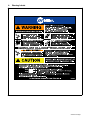
5. Warning Labels Continued
S-180 663
1 2 3 4 5
6
7 8 9
1 Warning! Watch Out! There are
possible hazards as shown by the
symbols.
2 Electric shock from wiring can kill.
3 Disconnect input plug or power before
working on machine.
4 Moving parts, such as fans, can cut
fingers and hands and cause injury.
Keep away from moving parts.
5 Wear safety glasses with side shields.
6 Read the Owner’s Manual before
working on this machine.
7 Read the labels on the welding power
source, wire feeder, or other major
equipment for welding safety
information.
8 Recycle or dispose of used coolant in
an environmentally safe way.
9 Do not remove or paint over (cover)
the label.
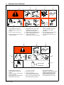
S-178 910
=
043 810 (HF)
043 809 (AL)
100 h. std.
21 3
6
4
7
5
1 Warning! Watch Out! There are
possible hazards as shown by the
symbols.
2 Disconnect input plug or power before
working on machine.
3 Wear safety glasses with side shields.
4 Plugged filter or hoses cause
overheating and damage.
5 Read Owner’s Manual.
6 Check and clean filter every 100
hours; also check condition of hoses.
7 Use Low Conductivity Coolant No. 043
810 for High-Frequency assisted or
Gas Tungsten Arc Welding
applications. Use Aluminum Protecting
Coolant No. 043 809 where coolant
contacts aluminum parts or for Gas
Metal Arc Welding applications or
where High Frequency is not used.

OM-231 313 Page 3
6. Symbols And Definitions
Hz
Hertz Input Power Power On Indicator
Water (Coolant)
Output
Water (Coolant) In-
put
Line Connection
Single-Phase
Alternating
Current
U
1
Primary Voltage
I
1max
Rated Maximum
Supply Current
IP
Degree Of
Protection
P
max
Rated maximum
power
Pl/
min
Power liters per
minute
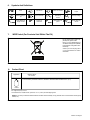
7. WEEE Label (For Products Sold Within The EU)
Do not discard product (where ap-
plicable) with general waste.
Reuse or recycle Waste Electrical
and Electronic Equipment (WEEE)
by disposing at a designated collec-
tion facility.
Contact your local recycling office
or your local distributor for further
information.
8. Coolant Chart
Low Conductivity Coolant No. 043 810**; Distilled Or Deionized Water OK Above 32° F (0° C)
GTAW Or Where
HF* Is Used
Application
*HF: High Frequency Current
**Coolant 043 810, a 50/50 solution, protects to -37° F (-38°C) and resist algae growth.
Coolant
NOTICE − Use of any coolant other than that listed in the table voids the warranty on any parts that come in contact with the coolant (pump,
radiator, etc.).

OM-231 313 Page 4
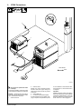
9. GTAW Connections
804 846-A
Tools Needed:
5/8 in
1
2
3
4
! Do not move or operate unit where
it could tip.
To prevent overheating, make sure cooling
unit is positioned so airflow is not restricted.
NOTICE − If welding power source has a
water valve, do not connect hoses to water
valve. Connect hoses as shown.
1 Coolant Out Hose
2 Coolant In Hose
Fittings have 5/8-18 left-hand threads.
Connect hoses with proper fittings as
shown. Some power sources may require
a TIG block.
3 Coolant Tank Cap
4 115 Volt AC Grounded Receptacle
An individual branch circuit capable of car-
rying 15 amperes and protected by fuses
or circuit breakers is recommended. Rec-
ommended fuse or circuit breaker size is
15 amperes.
Operation:
Fill tank with proper coolant. Use table in
Section 8 to select proper coolant. Maintain
coolant level at approximately 1 in (25 mm)
below top of filler neck. Connect hoses as
shown. Unit turns on when plugged in.

OM-231 313 Page 5
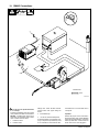
10. GMAW Connections
804 845-A
Tools Needed:
5/8 in
! Do not move or operate unit where
it could tip.
To prevent overheating, make sure cooling
unit is positioned so airflow is not restricted.
NOTICE − If welding power source has a
water valve, do not connect hoses to water
valve. Connect hoses as shown.
1 Coolant Out Hose
2 Coolant In Hose
Fittings have 5/8-18 left-hand threads.
Connect hoses with proper fittings as
shown.
3 Coolant Tank Cap
4 115 Volt AC Grounded Receptacle
An individual branch circuit capable of car-
rying 15 amperes and protected by fuses
or circuit breakers is recommended. Rec-
ommended fuse or circuit breaker size is
15 amperes.
Operation:
Fill tank with proper coolant. Use table in
Section 8 to select proper coolant. Maintain
coolant level at approximately 1 in (25 mm)
below top of filler neck. Connect hoses as
shown. Unit turns on when plugged in.
2
1
3
4

OM-231 313 Page 6
11. Routine Maintenance
! Disconnect power
before maintaining.
n = Check Z = Change ~ = Clean Δ = Repair l = Replace
* To be done by Factory Authorized Service Agent
Every
3
Months
~Coolant Strainer,
durning heavy service,
clean more frequently.
~ Blow out heat exchanger fins.
nCheck coolant level. Top off with
distilled or deionized water if necessary.
Every
6
Months
nlHoses
nl Labels
ZReplace coolant.
m30 Torx
Tools Needed:
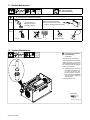
12. Coolant Maintenance
804 649-A / Ref. 801 194
! Disconnect input power be-
fore maintaining.
1 Coolant Filter
Unscrew housing to clean filter.
Changing coolant: Drain coolant by
tipping unit to rear, or use suction
pump. Fill with clean water and run
for 10 minutes. Drain and refill with
coolant (see section 8).
. If replacing hoses, use hoses
compatible with ethylene gly-
col, such as Buna-n, Neo-
prene, or Hypalon. Oxy-acety-
lene hoses are not compatible
with any product containing
ethylene glycol.
Install cover if removed.
1

OM-231 313 Page 7
13. Troubleshooting
Trouble Remedy
Coolant system does not work. Be sure input power cord is plugged in to energized receptacle.
Check line fuses or circuit breaker, and replace or reset if necessary.
Motor overheated. Unit starts running when motor has cooled.
Have Factory Authorized Service Agent check Power switch S1 and motor (Mot).
Decreased or no coolant flow. Add coolant.
Check for clogged hoses or coolant filter. Clean filter or clean / replace hoses if necessary.
Disconnect pump, and check for sheared coupling. Replace coupling if necessary.
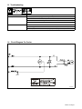
14. Circuit Diagram For Cooler
228 525-B

OM-231 313 Page 8
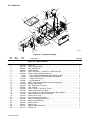
15. Parts List
804 838-C
1
4
5
10
7
11
12
8
9
6
13
14
15
16
17
19
20
21
22
24
23
15
15
25
26
27
28
29
30
37
36
31
35
34
33
2
3
18
32
38
39
40
41
42
43
Figure 15-1. Complete Assembly
Description
Part
No.
Dia.
Mkgs.
Item
No.
Figure 15-1. Main Assembly
Quantity
1 230 156 Cover, top 1. . . . . . . . . . . . . . . . . . . . . . . . . . . . . . . . . . . . . . . . . . . . . . . . . . . . . . . . . . . . . . . . . . . . . . . .
2 +192 449 Label, warning/caution 1. . . . . . . . . . . . . . . . . . . . . . . . . . . . . . . . . . . . . . . . . . . . . . . . . . . . . . . . . . . . .
3 228 551 Plug, w/Leads Fan 1. . . . . . . . . . . . . . . . . . . . . . . . . . . . . . . . . . . . . . . . . . . . . . . . . . . . . . . . . . . . . . . . .
4 226 965 Panel, Side Rh 1. . . . . . . . . . . . . . . . . . . . . . . . . . . . . . . . . . . . . . . . . . . . . . . . . . . . . . . . . . . . . . . . . . . .
5 228 519 Hose, nprn brd no 1 X .250 ID X .455 OD X 9.000 1. . . . . . . . . . . . . . . . . . . . . . . . . . . . . . . . . . . . .
6 228 508 Pump, Coolant w/Fittings (Includes) 1. . . . . . . . . . . . . . . . . . . . . . . . . . . . . . . . . . . . . . . . . . . . . . . . . .
7 5523 Ftg, Hose Brs Barbed Elbow M 3/8 TBG X 3/8 NPT 2. . . . . . . . . . . . . . . . . . . . . . . . . . . . . . . . . . . . . . .
8 173 999 Pump, Coolant 100 GPH w/V-Band CW Rotation 1. . . . . . . . . . . . . . . . . . . . . . . . . . . . . . . . . . . . . .
9 134 795 Coupler, Drive Pump 1. . . . . . . . . . . . . . . . . . . . . . . . . . . . . . . . . . . . . . . . . . . . . . . . . . . . . . . . . . . . . . .
10 196 990 Ftg, Brs Barbed 1. . . . . . . . . . . . . . . . . . . . . . . . . . . . . . . . . . . . . . . . . . . . . . . . . . . . . . . . . . . . . . . . . . .
11 173 263 Motor, 1/4hp 115vac 50/60hz 1425/1725 Rpm Dual 1. . . . . . . . . . . . . . . . . . . . . . . . . . . . . . . . . . . . .
12 226 966 Bracket, Motor Mount 1. . . . . . . . . . . . . . . . . . . . . . . . . . . . . . . . . . . . . . . . . . . . . . . . . . . . . . . . . . . . . .
13 166 608 Cap, Tank Screw−on w/Vent 1. . . . . . . . . . . . . . . . . . . . . . . . . . . . . . . . . . . . . . . . . . . . . . . . . . . . . . . . .
14 226 932 Tank, Coolant 1. . . . . . . . . . . . . . . . . . . . . . . . . . . . . . . . . . . . . . . . . . . . . . . . . . . . . . . . . . . . . . . . . . . . .
15 228 529 Hose, .375 ID X .650 OD X 19.500 3. . . . . . . . . . . . . . . . . . . . . . . . . . . . . . . . . . . . . . . . . . . . . . . . . .
16 155 436 Label, Ground/Protective Earth 1. . . . . . . . . . . . . . . . . . . . . . . . . . . . . . . . . . . . . . . . . . . . . . . . . . . . . .
17 163 562 Light, Ind Wht Lens 125vac Snap−in Neon Non−relampa 1. . . . . . . . . . . . . . . . . . . . . . . . . . . . . . . .
18 231 308 Label, Rating Card CSA C US 300245 1. . . . . . . . . . . . . . . . . . . . . . . . . . . . . . . . . . . . . . . . . . . . . . . .
19 213 053 Panel, Louver Cover 1. . . . . . . . . . . . . . . . . . . . . . . . . . . . . . . . . . . . . . . . . . . . . . . . . . . . . . . . . . . . . . .
20 230 151 Plate, Indicator Front Cooler 1. . . . . . . . . . . . . . . . . . . . . . . . . . . . . . . . . . . . . . . . . . . . . . . . . . . . . . . . .
21 226 940 Valve, Check Bidirectional Assy 2. . . . . . . . . . . . . . . . . . . . . . . . . . . . . . . . . . . . . . . . . . . . . . . . . . . . . .
22 230 155 Backet, Valve Mounting 2. . . . . . . . . . . . . . . . . . . . . . . . . . . . . . . . . . . . . . . . . . . . . . . . . . . . . . . . . . . . .
23 226 964 Panel, Side Lh 1. . . . . . . . . . . . . . . . . . . . . . . . . . . . . . . . . . . . . . . . . . . . . . . . . . . . . . . . . . . . . . . . . . . . .
24 226 931 Base, Cooler 1. . . . . . . . . . . . . . . . . . . . . . . . . . . . . . . . . . . . . . . . . . . . . . . . . . . . . . . . . . . . . . . . . . . . . .
25 232 424 Radiator, Heat Exchanger 1. . . . . . . . . . . . . . . . . . . . . . . . . . . . . . . . . . . . . . . . . . . . . . . . . . . . . . . . . . .
26 231 341 Plenum, Air 1. . . . . . . . . . . . . . . . . . . . . . . . . . . . . . . . . . . . . . . . . . . . . . . . . . . . . . . . . . . . . . . . . . . . . . .

OM-231 313 Page 9
Description
Part
No.
Dia.
Mkgs.
Item
No.
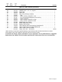
Figure 15-1. Main Assembly (continued)
Quantity
27 213 072 Fan, Muffin 1. . . . . . . . . . . . . . . . . . . . . . . . . . . . . . . . . . . . . . . . . . . . . . . . . . . . . . . . . . . . . . . . . . . . . . . .
28 233 164 CABLE, Power 11 ft 4 in. 16 ga 3c 1. . . . . . . . . . . . . . . . . . . . . . . . . . . . . . . . . . . . . . . . . . . . . . . . . .
29 228 498 Panel, Rear 1. . . . . . . . . . . . . . . . . . . . . . . . . . . . . . . . . . . . . . . . . . . . . . . . . . . . . . . . . . . . . . . . . . . . . . .
30 196 312 Guard, Fan 1. . . . . . . . . . . . . . . . . . . . . . . . . . . . . . . . . . . . . . . . . . . . . . . . . . . . . . . . . . . . . . . . . . . . . . .
31 228 520 Filter, Assy w/Fittings (Includes) 1. . . . . . . . . . . . . . . . . . . . . . . . . . . . . . . . . . . . . . . . . . . . . . . . . . . . .
32 215 667 Filter 1. . . . . . . . . . . . . . . . . . . . . . . . . . . . . . . . . . . . . . . . . . . . . . . . . . . . . . . . . . . . . . . . . . . . . . . . . . . . .
33 228 532 Hose, .375 ID X .650 OD X 1.415 2. . . . . . . . . . . . . . . . . . . . . . . . . . . . . . . . . . . . . . . . . . . . . . . . . . .
34 231 311 Ftg, Hose Nyl Elbow Barbed 3/8 X 3/8 90 Deg 2. . . . . . . . . . . . . . . . . . . . . . . . . . . . . . . . . . . . . . . . .
35 226 967 Bracket, Mtg Filter 1. . . . . . . . . . . . . . . . . . . . . . . . . . . . . . . . . . . . . . . . . . . . . . . . . . . . . . . . . . . . . . . . . .
36 236 084 Hose, .375 ID X .650 OD X 10.500 1. . . . . . . . . . . . . . . . . . . . . . . . . . . . . . . . . . . . . . . . . . . . . . . . . .
37 228 530 Hose, .375 ID X .650 OD X 8.375 1. . . . . . . . . . . . . . . . . . . . . . . . . . . . . . . . . . . . . . . . . . . . . . . . . . .
38 231 368 Elbow/Tubing Assy, Return 1. . . . . . . . . . . . . . . . . . . . . . . . . . . . . . . . . . . . . . . . . . . . . . . . . . . . . . . . . .
39 231 367 Elbow/Tubing Assy, Pick-up 1. . . . . . . . . . . . . . . . . . . . . . . . . . . . . . . . . . . . . . . . . . . . . . . . . . . . . . . . .
40 231 284 Bushing, Tank Coolant 2. . . . . . . . . . . . . . . . . . . . . . . . . . . . . . . . . . . . . . . . . . . . . . . . . . . . . . . . . . . . . .
41 180 663 Label, Warning General Precautionary Static&wire Fe 1. . . . . . . . . . . . . . . . . . . . . . . . . . . . . . . . . .
42 178 910 Label, Caution Incorrect Coolant Wordless Intl 1. . . . . . . . . . . . . . . . . . . . . . . . . . . . . . . . . . . . . . . .
43 219 178 Label, Caution Incorrect Coolant 1. . . . . . . . . . . . . . . . . . . . . . . . . . . . . . . . . . . . . . . . . . . . . . . . . . . . .
*010 323 Clamp, Hose .250 − .625 Clp Dia 2/Hose. . . . . . . . . . . . . . . . . . . . . . . . . . . . . . . . . . . . . . . . . . . . . . . . . . . .
+When ordering a component originally displaying a precautionary label, the label should also be ordered.
*Hose clamps (2 per hose) should be ordered for any hose removal or repair.
To maintain the factory original performance of your equipment, use only Manufacturer’s Suggested
Replacement Parts. Model and serial number required when ordering parts from your local distributor.

ORIGINAL INSTRUCTIONS − PRINTED IN USA © 2009 Miller Electric Mfg. Co. 2009−01
Miller Electric Mfg. Co.
An Illinois Tool Works Company
1635 West Spencer Street
Appleton, WI 54914 USA
International Headquarters−USA
USA Phone: 920-735-4505 Auto-Attended
USA & Canada FAX: 920-735-4134
International FAX: 920-735-4125
For International Locations Visit
www.MillerWelds.com
Model Name Serial/Style Number
Purchase Date (Date which equipment was delivered to original customer.)
Distributor
Address
City
State Zip
Please complete and retain with your personal records.
Always provide Model Name and Serial/Style Number.
Contact a DISTRIBUTOR or SERVICE AGENCY near you.
Welding Supplies and Consumables
Options and Accessories
Personal Safety Equipment
Service and Repair
Replacement Parts
Training (Schools, Videos, Books)
Technical Manuals (Servicing Information
and Parts)
Circuit Diagrams
Welding Process Handbooks
Contact the Delivering Carrier to:
For Service
Owner’s Record
File a claim for loss or damage during
shipment.
For assistance in filing or settling claims, contact
your distributor and/or equipment manufacturer’s
Transportation Department.
Contact your Distributor for:
To locate a Distributor or Service Agency visit
www.millerwelds.com or call 1-800-4-A-Miller
-
 1
1
-
 2
2
-
 3
3
-
 4
4
-
 5
5
-
 6
6
-
 7
7
-
 8
8
-
 9
9
-
 10
10
-
 11
11
-
 12
12


Miller Coolmate 3.5 Le manuel du propriétaire
- Catégorie
- Système de soudage
- Taper
- Le manuel du propriétaire
- Ce manuel convient également à
dans d''autres langues
- English: Miller Coolmate 3.5 Owner's manual
Documents connexes
-
Miller Coolmate 3.5 Le manuel du propriétaire
-
-
-
-
-
-
-
-
-