0
GEAppliances.com
Safety Information ........ 2,s
Operating/Care and
Cleaning Instructions
Charcoal Filter ................... 5
Grease Filter ..................... 4
Hood Light ....................... 5
Hood Surfaces ................... 5
Controls ......................... 4
Installation
Instructions ................ 6-14
Consumer Support
consumer support ...... Back Cover
Warranty ....................... 15
"k
I
CERTIFIED
JV247*-Vent & Recirculation
options
JV248*-Vent & Recirculation
options
JN327-Recirculotion only
JV338*-Vent options only
JV347*-Vent & Recirculotion
options
JV348*-Vent & Recirculotion
options
JV367*-Vent & Recirculotion
options
RN328-Recirculotion only
AV447*-Vent & Recirculotion
options
Write the model and serial numbers here:
Model #
Serial #
Youcan find them on a label on the
back wall of the hood.
49-80589-5 08-13 GE

IMPORTANT SAFETY INFORMATION.
READ ALL INSTRUCTIONS BEFORE USING.
SAFETYPRECAUTIONS
A WARNING- TOREDUCETHERISKOFFIRE,
ELECTRICSHOCKORINJURYTOPERSONS,OBSERVETHE
FOLLOWING:
A. Usethis unitonlyinthemannerintendedbythemanufacturer.If
you havequestions,contactthe manufacturer.
B. Beforeservicingor cleaningunit,switchpoweroff atservice
paneland lockthe servicedisconnectingmeansto prevent
powerfrom beingswitchedonaccidentally.Whentheservice
disconnectingmeanscannotbelocked,securelyfastena
prominentwarning device,suchasa tag,to theservicepanel.
C. Donotusethis unitwith anysolid-statespeedcontroldevice.
D. If usinga cordconnectionkit,useonlywith rangehoodcord-
connectionkitJXHC1that hasbeeninvestigatedandfound
acceptablefor usewith this modelrangehood.
E. Thisunitmustbegrounded.
CAUTION- mRGENERALVENTILATINGUSEONLY
DONOTUSETOEXHAUSTHAZARDOUSOREXPLOSIVEMATERIALS
ANDVAPORS.
WARNING- TOREDUCETHERISKOFINJURYTO
PERSONSIN THEEVENTOFA RANGETOPGREASEFIRE,OBSERVE
THEFOLLOWING*:
A. SMOTHERFLAMESwith a close-fittinglid,cookiesheetor metal
tray,thenturn off theburner.BECAREFULTOPREVENTBURNS.
Ifthe flamesdo notgo outimmediately,EVACUATEANDCALL
THEFIREDEPARTMENT.
B. NEVERPICKUPAFLAMINGPAN-Youmay beburned.
C. DONOTUSEWATER,includingwetdishclothsor towels-a violent
steamexplosionwillresult.
D. Usean extinguisherONLYif:
1. Youknowyou havea ClassABCextinguisher,andyou already
know howtooperateit.
2. Thefireissmallandcontainedin theareawhereitstarted.
3. Thefiredepartmentisbeingcalled.
4. Youcanfight thefirewith yourbackto anexit.
* Basedon "KitchenFireSafetyTips"publishedbyNFPA.
A WARNING- TOREDUCETHERISKOFARANGE
TOPGREASEFIRE:
A. Neverleavesurfaceunitsunattendedat highsettings.Boilovers
causesmokingand greasyspilloversthat mayignite.Heatoils
slowlyon lowor mediumsettings.
B. Alwaysturn hoodONwhencookingon highheator when
flamb_ingfood(i.e.CrepesSuzette,CherriesJubilee,Peppercorn
BeefFlamb_).
C. Cleanventilatingfansfrequently.Greaseshouldnot beallowedto
accumulateon fanor filter.
D. Useproperpan size.Alwaysusecookwareappropriateforthe
sizeofthe surfaceelement.
,&WARNING- TOREDUCETHERISKOFFIRE,
ELECTRICSHOCKORINJURYTOPERSONS,OBSERVETHE
FOLLOWING:
A. Installationwork andelectricalwiring mustbedonebyqualified
person(s)inaccordancewith allapplicablecodesandstandards,
includingfire-ratedconstruction.
B. Sufficientair isneededfor propercombustionandexhausting
of gasesthroughthe flue(chimney)offuel burningequipment
to preventbackdrafting.Followtheheatingequipment
manufacturer'sguidelineandsafetystandardssuchas
thosepublishedbythe NationalFireProtectionAssociation
(NFPA),theAmericanSocietyfor Heating,RefrigerationandAir
ConditioningEngineers(ASHRAE)andthe localcodeauthorities.
Whenapplicable,installanymakeup(replacement)airsystem
inaccordancewith localbuildingcoderequirements.Visit
GEAppliances.comforavailablemakeupairsolutions.
C. Whencuttingor drillingintowallor ceiling,do notdamage
electricalwiringand otherhiddenutilities.
D. Ductedfansmustalwaysbeventedto the outdoors.
,&WARNING- TOREOUCETHERISKOFFIREANDTO
PROPERLYEXHAUSTAIR,BESURETODUCTAIROUTSIDE--DONOT
VENTEXHAUSTAIRINTOSPACESWITHINWALLSORCEILINGSOR
INTOATTICS,CRAWLSPACESORGARAGES.
A WARNING- TOREOUCETHERISKOFFIRE,USE
ONLYMETALDUCTWORK.
[] Donotattempt to repairor replaceanypart ofyourhoodunlessit
isspecificallyrecommendedin thisguide.Allotherservicingshould
be referredto a qualifiedtechnician.
READAND FOLLOWTHISSAFETYINFORMATIONCAREFULLY.
READAND SAVETHESEINSTRUCTIONS

INSTRUCTIONS DE SECURITE IMPORTANTES.
LISEZ TOUTES LES INSTRUCTIONS AVANT D'UTILISER.
PRdLCAUTIONSEN NATI_LREDE SdLCURITdL
AA VERTISSEMENT- POURR_DUIRELE
RISQUED'INCENDIE,DESECOUSSEE-LECTRIQUEOUDE BLESSURE
CORPORELLE,OBSERVEZLESPRECAUTIONSSUIVANTES:
A. N'utilisezcet appareil que de la mani_re pr@ue par lefabricant. Si
vous avezdesquestions,appelez lefabricant.
B. Avantde r@arer ou de nettoyer votre appareil,d_branchez
le courant au niveaudu panneau de serviceet verrouillezles
m_canismesde d_branchement deservice pour @itertout
branchement accidentelau courant.Sivous ne pouvezpas
verrouiller lesm_canismesde d_branchement deservice,attachez
soigneusement un avertissementbien visible,comme une_tiquette,
au panneau deservice.
C. N'utilisezjamais cet appareil avec un m_canisme de r_glage de la
vitessea semi-conducteurs.
D. Sivous utilisezI'ensemblede cordon de raccordement, utilise
seulement avec I'ensembledecordon de raccordement pour hotte
JXHC1.Suite_ un examen technique, I'articleJXHC1s'est av@_
compatible avec cemo@le de hotte.
E. Cetappareil doit _tre bien mis 5 la terre.
_kATFENTION- UN,OUEMENT;_USAGE_E
VENTILATIONGENERALE.N'UTILISEZJANAISPOURL'ECHAPPEHENTDE
HATIERESETDEVAPEURSEXPLOSIVES.
,_AVERTISSEMENT- POURR_DUIRELERISQUE
DEBLESSURECORPORELLESIDE LAGRAISSEPRENDFEUSURLA
SURFACEDECUISSONDELACUISINIE-RE,SUIVEZLESINSTRUCTIONS
SUIVANTES*:
A. ETOUFFEZLESFLAMIES avec un couvercle qui convient, unet61ea
biscuitsou un plateau en m@tal,j_uis@teignezle br01eur.FAITESBIEN
ATTENTIONDENEPASVOUSBRULER.Silesflammes ne s'@teignent
pas imm@diatement,SORTEZETAPPELEZLESPOMPIERS.
B. NEDEPLACEZJAIAIS UNECASSEROLLEOUIFLAIBE - Vous pouvez
vous br01er.
C. N'UTILISEZJAMAISD'EAU,en particulier de servietteou dechiffon
mouill@- ilse produira une explosion violentede vapeur brOlante.
D. N'UTILISEZUNEXTINCTEURque si:
:1..Vousavez un extincteur de classeABCet vous savezcomment
I'utiliser;
2. Lefeu est r@duitetconfin@@I'endroit o_]ilacommenc@;
3. Vousavez d@jaappel@les pompiers;
4. Vouscombattez lesflammes en tournant le dos@une sortie.
* Bas@sur I'ouvrage intitul@<<KitchenFireSafetyTips>>publi@par la NFPA.
,_AVERTISSEMENT- POURR_DUIRELE
RISQUED'UN FEUDEGRAISSESURLASURFACEDECUISSONDELA
CUISINIERE:
A. Nelaissezjamais sans surveillance lesunit@sde cuisson de surface
a unetemperature_lev@.Lebouillonnementoccasionnedes
d_bordements fumants etgraisseux qui peuvent prendre feu.
Chauffeza feu doux les substanceshuileuses,
avec un r_glage has ou moyen.
B. ALLUIVlEZtoujours la hotte en casde cuisson a
feu @lev@ou Iorsquevous faites flamber des aliments (par exemple,
cr@pesSuzette,cerisesjubil@es,bceuf
au poivre flamb@).
permettre uneaccumulation de graisse sur leventilateur ou sur le
filtre.
D. Utilisezune casserolede bonne taille.Utiliseztoujours un ustensilede
cuisine quiconvienne au diam@tre
de I'@l@mentde cuisson.
,_AVERTISSEMENT- POURR_DUIRELE
RISQUED'INCENDIE,DESECOUSSEELECTRIQUEOUDE BLESSURE
CORPORELLE,OBSERVEZLESPRECAUTIONSSUIVANTES:
A. Vous devezfaire ex@cutertousles travaux d'installation et de
c6blage @lectriquepar une personnequalifi@e,conform@ment6 tous
lescodeset les normes envigueur,
en particulier ceuxde construction relatifsaux incendies.
B. Vous devez assezd'air pour avoir unebonne combustion et
permettre I'@vacuationdes gaz par le conduit de chemin@edu
mat@ielde combustion du carburant, afin d'@iter tout retour
d'air. Suivezlesdirectivesdu fabricant de mat@ieldecombustion
et lesnormes de s@curit@comme cellespubli@s par la National
FireProtectionAssociation (NFPA),I'AmericanSocietyfor Heating,
Refrigerationand AirConditioning Engineers(ASHRAE),ainsi queles
modalit@sdes codesIocaux.Lecas@ch@ant,installezun syst@mede
compensation d'air (remplacement)conform@mentaux conditions
des codesIocaux du b6timent. VisitezlesiteGEAppliances.com
pour conna?trelessolutions offertes en mati@rede syst@mede
compensation d'air.
C. Sivous faites un trou ou uneouverture dans un mur
ou un plafond,n'endommagez paslesills @lectriqueset lesautres
installations cach@esdeservicepublic.
D. Vous deveztoujours alimenter lesventilateurs dans
les conduits en air en provenance de I'ext@ieur.
_A VERTISSEMENT- POURR_DUIRELERISQUE
D'INCENDIEETEVACUERADEQUATEMENTL'AIR_ASSUREZ-VOUSDE
FAIREDEBOUCHERLACONDUITED'AIRAL'EXTERIEUR--NEVENTILEZ
PASL'AIRE-VACUE-DANSDESESPACESCOMPRISA L'INTE-RIEURDE
MURS,D'UN PLAFOND,
D'UN GRENIER,D'UN VIDESANITAIREOUD'UNGARAGE.
_A VERTISSEMENT- POURR_DUIRELERISQUE
D'INCENDIE,N'UTILISEZQUEDESCONDUITSENMETAL.
[] N'essayezjamais de remplacerou de r@arer un _l_ment devotre
hotte sile present manuel ne le recommande pasexpress@ment.Tout
autreentretien doit @treeffectu_ par un technicien qualifi_.
LISEZ ETSUIVEZATTENTIVENENT CESINSTRUCTIONS.
LISEZ ET CONSERVEZ CES INSTRUCTIONS

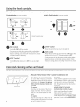
Using the hood controls.
Throughout thismanual, featuresand appearancemay varyfromyour model.
Control Knobs (on some models)
OFF OFF
oN l
NITE J
, e
(AV447models only)
FAN Control
Turn to HI, PIED or LO as needed.
Continuous use of the fan system while cooking helps
keep the kitchen comfortable and less humid. It also
reduces cooking odors and soiling moisture that create
a frequent need for cleaning.
LIGHT Control
Turn to ONwhile cooking or to NITEfor use as a night
light.
Switch Pad Controls (onsome models)
ON
OFF
HI
_OFF
LO
LIGHT Control
Pressthe pad at the top to turn the light ON.
FAN Control
Pressthe pad at the top to turn the fan on HI and at the
bottom to turn it on LO.The center position is OFF.
Continuous use of the fan system while cooking helps
keep the kitchen comfortable and less humid. It also
reduces cooking odors and soiling moisture that create
a frequent need for cleaning.
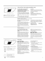
Care and cleaning of the vent hood.
Be sure electrical power is off and all surfaces are cool before cleaning or servicing any part of the vent hood.
Gtease filter
4
Reusable Metal Grease Filter--Ducted Installations Only
The efficiency of your hood depends To clean:
on a clean filter. Frequency of cleaning Soak and then agitate it in a hot water
depends on hood use and the type of and detergent solution. Light brushing
cooking you do. However, the grease can be used to remove embedded
filter should be cleaned at least once dirt. Rinse,shake and let it dry before
a month, replacing.
To remover
Pull down on the center of the front
edge of the filter. The filter will then
slip out of the retaining tabs on the
back.
To replace:
Slip the back edge of the filter into the
retaining tabs and push the front edge
up until it snaps into place.
NEVEROPERATETHEHOOD
WITHOUT THEFILTERIN PLACE.
With careful handling, the metal
filter will last for years. If a new
replacement filter becomes necessary,
order the part from your dealer. Order
genuine GEpart number WBO2X8391.

Replaceable charcoal filter
NOTE:DONOTrinse, or put charcoal
filters in an automatic dishwasher.
Charcoal Filter--Recirculating Installations Only
Thecharcoal filtercannot be cleaned.
Itmust be replaced. Orderfilterno.
WBO2XI0700.Replacementfilterscanbe
orderedfromyour GEsupplier.
tfthehoodisnotventedtotheoutside,the
airwillberecirculatedthrougha disposable
charcoalfilterthat helpsremovesmokeand
odors.
Thecharcoalfiltershouldbereplacedafter6
to 12months(dependingonhoodusage).
Toremove:
Pulldownonthecenterofthefrontedge
ofthefilter.Thefilterwillthenslipoutofthe
retainingtabsontheback.
Toreplace:
Slipthebackedgeofthefilter intothe
retainingtabsandpushthefront edgeup
untilitsnapsintoplace.
Stainless Steel Surfaces (on some models)
Donot usea steel-woolpad;it will scratch
thesurface.
Tocleanthestainlesssteelsurface,use
warm sudsywateror a stainlesssteelcleaner
or polish.Alwayswipethesurfaceinthe
directionofthegrain.Followthecleaner
instructionsforcleaningthestainlesssteel
surface.
Toinquireaboutpurchasingstainlesssteel
appliancecleanerorpolish,ortofindthe
locationofa dealernearestyou,pleasecall
ourtoll-freenumber:
NationalPartsCenter 800.626.2002
GEApplianceParts.com
Painted Surfaces Ion some models)
Donot usesteel-woolpadsor other
abrasivecleaners.Theywillscratchthe
surface.
Cleangrease-ladensurfacesofthehood
frequently.Tocleanthehoodsurface,use
a hot,dampclothwith a milddetergent
suitableforpaintedsurfaces.Aboutone
tablespoonof ammoniamaybeaddedto
thewater.Usea clean,hot,dampclothto
removesoap.Drywith a dry,cleancloth.
NOTE:Whencleaning,takecarenotto
comeincontactwithfiltersandothernon-
enameledsurfaces.
A CAUtiON: whencleaningthe
hoodsurfaces,becertainthatyou donot
touchthelightbulbwithmoisthandsor
cloth.Awarm orhotlightbulbmaybreakif
touchedwith a moistsurface.Alwaysletthe
lightbulbcoolcompletelybeforecleaning
aroundiL
ht cover Hood Light
When using an energy saving bulb in your GEhood
make sureyou use either:
GELong Life Energy Smart'"Spiral®T2
Product Code:85383
Description: FLE!3HT2/2/SW/CD
or
GELongLifeEnergySnarl"A!7
ProductCode:47486
Description:FLE!!/2/A! 7×L/CD
Availableat www.gelighting.com
A CAUtiON:Letthelightbulb
coolcompletelybeforeremoving.Awarmor
hotbulbmaybreakiftouchedwith a moist
clothor hand.
Removethe bulbandreplaceitwith atype
A15incandescentlightbulbwith anordinary
screwbase,not morethan60 Watts,or a
typeA!7 orT2CompactFluorescent(CFL)
lightbulbwith anordinaryscrewbase,
notmorethan 13Watts.NOTE:Useonly
incandescentbulbsin modelsRN328,JN327
andJV338.
INPORTANT:Forinstallation,handlingand
disposalprecautions,referto thefluorescent
bulbpackagingliterature.
Toremovethelightcover
(onsomemodels):
• Pressthesideswith two fingersuntilthe
sideprongsare released.
• Liftthelightcoverandslideittowardyou
inonemotion.
Toreplacethelight coven
• Insertthepronglocatedattheendofthe
coverintothetopopening.
Gentlypushthecoverup andpressthe
sidestofit thesideprongsintotheside
openings.
Releaseandthecoverwilllockinposition.

I
I
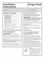
stall ti
str
cti
$
Ra e Hood
BEFORE YOU BEGIN
Readthese instructions completely and carefully.
• IMPORTANT - Save these instructions for
local inspector's use.
• IMPORTANT - Observe all governing
codes and ordinances,
• Note to Installer - Be sure to leave these
instructions with the Consumer.
• Note to Consumer - Keepthese instructions
for future reference.
• Skill level - Installation of this appliance requires
basic mechanical and electrical skills.
• Completion time - 30 minutes-3 hours
• Proper installation is the responsibility of the installer.
• Product failure due to improper installation is not
covered under the Warranty.
FOR YOUR SAFETY:
* WARNING - Beforebeginning the
installation, switch power off at service panel and
lock the service disconnecting means to prevent power
from being switched on accidentally. When the service
disconnecting means cannot be locked, securely fasten
a prominent warning device, such as a tag, to the
service panel.
OPTIONAL POWER CORD KIT JXHC1
An optional Power Cord Connection Kit, model JXHC1,
is available at extra cost from your GEsupplier for
installation using a standard 3-prong, grounded wall
outlet. Follow the Installation Instructions packed with
the kit to connect the power cord to the range hood.
6
DUCTWORK REQUIREMENTS
NOTE:Readthe ductwork sections only if you do not
have existing ductwork. If you have existing ductwork,
skip to the °'Damage" section and proceed.
AWARNING - TOREDUCETHERIsKOFFIREAND
TOPROPERLYEXHAUSTAIR,BESURETODUCTAIROUTSIDE--
DONOTVENTEXHAUSTAIRINTOSPACESWITHINWALLSOR
CEILINGSORINTOATTICS,CRAWLSPACESORGARAGES.
Theventing system must exhaust to the outside.
Thishood can be vented verticallythrough upper cabinetsor
horizontallythrough an outside wall. Ductworkisnot included.
Exhaust connection:
The hood exhaust has been designed to mate with
standard 3¼" x !0" rectangular ducting or 7" diameter
round ducting.
If a 6" round duct is required, a rectangular-to-round
transition adaptor must be used*. Do not use less than a
6" diameter duct.
Maximum duct length:
Forsatisfactory air movement, the total duct length
of a 3¼" x 10" rectangular, 6" or 7" diameter round
duct should not exceed 65 equivalent feet. See
the WORKSHEET-CALCULATETOTAL EQUIVALENT
DUCTWORKLENGTHsection.
NOTE:It isimportant that ducting be installed using the
most direct route and with as few elbows as possible.
This ensures clear venting of exhaust and helps prevent
blockages. Also, make sure dampers swing freely and
nothing is blocking the ducts. When applicable, install any
makeup (replacement) air system in accordance with local
building code requirements. Visit GEApplionces.com for
available makeup air solutions.
Elbows, transitions, wall and roofcaps, etc.,
present additional resistance to airflow and are equivalent
to a section of straight duct longer than their actual
physical size.When calculating the total duct length, add
the equivalent lengths of all transitions and adaptors plus
the length of all straight duct sections.The charts on the
following pages show you how to calculate total equivalent
ductwork length using the approximate feet of equivalent
length of some typical ducts.
* IMPORTANT:If a rectangular-to-round
transition adaptor isused, the bottom
corners of the damper will have to be
cut to fit, using the tin snips, in order
to allow free movement of the damper.
Equivalent lengths of duct pieces
are based on actual tests and reflect
requirements for good venting
performance with any hood.

Installation Instructions
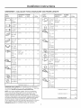
WORKSHEET--CALCULATE TOTAL EQUIVALENT DUCTWORK LENGTH
DUCT
PIECES
31A"x !0"
Rect.,
straight
7" Round,
straight
6" Round,
straight
EQUIVALENT NUMBER
LENGTH x USED
1Ft. x ( )
1Ft. x ( )
1Ft. x ( )
= TOTAL
= Ft.
= Ft.
= Ft.
31A"x !0" 14 Ft. x ( ) = Ft.
Rect. 90°
elbow
31A'x !0" 8 Ft. x ( ) : Ft.
Rect. 45°
elbow
i_ 31A'x !0" 33 Ft. x ( ) : Ft.
Rect. 90°
flat elbow
_ 31A'x !0" 24 Ft. x ( ) = Ft.
Rect. (18ft. w/o
wall cop damper) x ( ) = Ft.
with
damper
__ 1A'x !0" 2 Ft. x ( ) = Ft.
Rect. to
6" round
transition
__ 1A'x !0" 4 Ft. x ( ) = Ft.
Rect. to
6" round
transition
90° elbow
(_ " Round, 25 Ft. x ( ) = Ft.
90° elbow
(_ 6" Round, 16 Ft. x ( ) = Ft.
4S° elbow
Subtotal column ! = Ft.
MAXIMUM DUCT LENGTH: For satisfactory air movement,
the total duct length of a 3¼ x 10 rectangular, 7 diameter
round duct shoul8 not exceed 65 equivalent feet.
NOTE: Any home ventilation system, such as a ventilation.
hood, may interrupt the proper flow of combustion air and
exhaust required by fireplaces, gas furnaces,gas water .
heaters and other naturally vented systems. To minimize the
chance of interruption of such naturally vented systems, follow
the heating equipment manutacturer's guidelines and safety
standards such as those published by NFPA and ASHRAE.
When applicable, install any makeup (replacement) air system
in accordance with local building code requirements. Visit
GEAppliances.com for available makeup air solutions.
DUCT
PIECES
%
6" Round
wall cap
with
damper
6" Round
roof cap
6" Round
to
31A"x !0"
rect.
transition
6" Round
to
31A"x !0"
rect.
transition
90° elbow
7" Round,
90° elbow
7" Round,
45° elbow
EQUIVALENT
LENGTH
7" Round
wall cap
with
damper
7" Round
roof cap
53 Ft.
(39ft.w/o
damper)
72 Ft.
3 Ft.
9 Ft.
!4 Ft.
9 Ft.
28 Ft.
(21ft. w/o
damper)
NUMBER
× USED
x( )
x( )
x( )
x( )
x( )
x( )
x( )
x( )
x( )
= TOTAL
= Ft.
= Ft.
= Ft.
= Ft.
= Ft.
= Ft.
= Ft.
= Ft.
= Ft.
= Ft.
39 Ft. x ( )
_})_ 7" Round ! Ft. x ( ) = Ft.
to
31A"x !0"
rect.
transition
(_,,_ 7" Round 5 Ft. x ( ) = Ft.
to
31A"x !0"
rect.
transition,
90° elbow
Subtotal column 2 = Ft.
Subtotal column 1 = Ft.
Total ductwork = Ft.

Installation Instructions
DAMAGE - SHIPMENT/INSTALLATION
• If the unit is damaged in shipment, return the unit to the
store in which it was bought for repair or replacement.
• If the unit is damaged by the customer, repair or
replacement is the responsibility of the customer.
• If the unit is damaged by the installer (if other than
the customer), repair or replacement must be made by
arrangement between customer and installer.
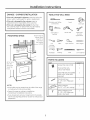
MOUNTING SPACE
24", 30" or 36" to
match cooktop
width
Bottom edge of
cabinet needs
to be 30" or
more from
the cooking
surface
66" or more
from the
floor to the
top of the
hood
NOTES:
,, Hood width may be greater than the width of the range
or cooktop, but it may not be smaller.
• Ensurethe range or cooktop isinstalled per
manufacturer's installation instructions.
• If you are going to vent your range hood to the outside,
seethe "Ducting Requirements"section for exhaust duct
preparation.
TOOLS YOU WILL NEED
Flat-blade and Phillips Pencil
screwdrivers
Saw (saber or Electric drill
keyhole)
Duct tape
Metal snips
(in some
applications)
1/4" Pliers
pivoting
hex socket
Flashlight Caulking
Tape measure
Level
Wire stripper
!/4" Nutdriver
PARTS INCLUDED
PART QUANTITY
Grease Filter only (JV338) 1
Charcoal Filter only 1
(JN327 and RN328)
Grease Filter and Charcoal Filter 2
(JV24X,JV347,JV348,JV367
andAV447)
i_ Mounting Screws 4
(8 - 18" x 3//4" Phillips pan
head)
<__ Exhaust Adaptor 1
(for 3¼" x 10" rect. venting)
Exhaust Adaptor Screw 1
(8 - 18" x 3/8" Phillips pan
head or hex head)
8

Installation Instructions
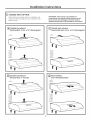
[] CHOOSE VENT OPTION
Determine the vent option that your installation will
require and that isavailable for your model from the
below choices.
IMPORTANT: If the hood is to be installed in a
recirculating, non-vented, ductless manner, do not
knock out any vent openings in the hood. Only an
electrical access hole will be knocked out of the hood.
r_ outside top exhaust
(Vertical duct-3-1/4" x 10" Rectangular)
JV338
JV247
JV248
JV547
JV548
JV567
AV447
[-_ Outside rear exhaust
(Horizontal duct-3-1/4" x 10" Rectangular)
JV338
JV247
JV248
JV547
JV548
JV567
AV447
E_] outside top exhaust
(Vertical duct-7" Round)
JV338
FD-] Recirculating
(non-vented/ductless)
JN327
RN528
9

Installation Instructions
[_] REMOVE EXHAUST ADAPTOR
If exhausting/venting using the 31/W'x 10" rectangular
duct--optional for JV247,JV248, JV338, JV347,JV348,
JV367 and AV447 models only:
Removethe exhaust adaptor from the insideof the hood.
Set it aside along with its mounting screws.
_-] REMOVE WIRING COVER
Removethe wiring cover from inside the hood.
Setthe cover and its mounting screws aside.
Wiring
cover
[] REMOVE FILTER
Removethe shipping tape holding the metal grease
filter in place. Pulldown on the center of the front edge
of the filter. Thefilter will then slip out of the retaining
tabs on the back.
Metal grease filter
[] REVERSE THE BAFFLE FOR DUCTED
INSTALLATIONS ONLY (JV247, JV248,
JV347, JV348, JV367 and AV447 models)
Ifthe hood isto be recirculated, skip to the next step.
Removethe baffle from the top of the hood. Reinstall
the baffle so the short side marked "VENTED"is visible.
Thelong side of the baffle should be inside the hood.
"VENTED"isvisible
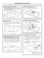
[_] REMOVE WIRING KNOCKOUT
Remove either the top or the back wiring knockout as
needed and install an approved strain relief clamp.
Top Back
knockout knockout
Strainrelief X Strainrelief
clamp
clamp
[_ REMOVE DUCT KNOCKOUT
If recirculating, non-vented ductless (JN327 and RN328,
and optional for JV247,JV248,JV347,JV348,JV367 and
AV447 models only),skip to Step 11 Dand proceed.
Using a flat-blade screwdriver, remove the appropriate
duct knockout from the top or back of the hood.
3¼" x 10" Rectongu!ar
vertical discharge.
Remove top rectangular
duct knockout only.
7" Round vertical discharge.
Remove circular duct
knockout only.
10
3k'J'x 10"Rectangular horizontal
discharge. Remove rear
rectangular duct knockout only.

Installation Instructions
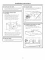
i-8-IFOR 3-1-4" × I0" RECTANGULAR
DUCTED DISCHARGE INSTALLATIONS
ONLY:
Attach exhaust adaptor/damper over the appropriate
knockout opening (for vertical or horizontal, depending
on installation) with two exhaust adaptor screws. Make
sure damper pivot is nearest to top/back edge of hood.
Remove tape from damper flap.
Exhaust adaptor/damper
(vertical discharg_ position)
Pivot
(depending on
installation)
Top/back edge
Exhaust adaptor/damper
(horizontal discharge position)
ITO]FOR RECESSED-BOTTOM CABINETS
ONLY
Woodshims
(minimum thickness 3/8")
. If the cabinets have front, side or back trim, make
2 wood shims a minimum of 3/8" thick and cut to fit
the width of the inner recessed cabinet bottom. Attach
them to the cabinet bottom recess on both sides. See
Step !1 for marking locations.
@ FOR 7" ROUND VERTICAL DUCTED
DISCHARGE INSTALLATIONS ONLY:
Bend up the duct alignment ears in preparation for
later attachment of the 7" duct.
11

Installation Instructions
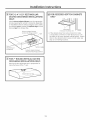
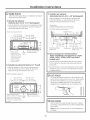
[] MARK HOLES
Select the vent option that your installation will require
and proceed to that section:
A.Outside top exhaust
(Vertical duct-3-1/4" x 10" Rectangular)
. Use the diagram or the hood as a template and mark
the locations on the cabinet for ductwork, electrical
wiring and keyhole screw slots.
Hood mounting screws (4)
10sA" (2W' hood)
133A" (30" hood)
:]_03_'' (24" hood)
133A'' (30" hood)
163A'' (36" hood)
shims
(recessed-bottom
cabinets only-shims
must be a minimum
of 3/8" thick and cut
to fit the width of
the inner recessed
cabinet bottom)
Electricalaccesshole
Center (incabinet bottom)
line
B.Outside top exhaust (Vertical duct-7" Round)
. Use the diagram or the hood as a template and
mark the locations on the cabinet for ductwork,
electrical wiring and keyhole screw slots.
Hood mounting screws (4)
i0¾" (24" hood) i0_/' (24" hood)
13¾" (30" hood) 13_/' (30" hood)
(36"
Access
hole for
round duct
Wood shims (recessed-
bottom cabinets only-shims Center
must be a minimum of 3/8" line
thick and cut to fit the width
of the inner recessed cabinet
bottom)
Electrical access
hole (incabinetbottom)
C.Outside rear exhaust
(Horizontalduct-3-1/4" x 10" Rectangular)
. Use the diagram or the hood as a template and
mark the locations on the cabinet for ductwork,
electrical wiring and keyhole screw slots.
Woodshims
(recessed-bottom cabinets only-shims must be
a minimum of 3/8" thick and cut to fit the width
of the inner recessed cabinet bottom)
½,, 1_/' ] | I
Cabinet front
Cabinet ± _ _ I_'_, 1
bottom l_--s¼" _ _--s_" _4 I
J-_---10s/4" 124" hood)--_ _---10¾" 124"hood)---_
--'_13_' 130" hood) 13sA'' 130"hood)
16YJ'136"hood) 16_"136"hood)
Hood mounting Center line Electrical access
screws (4) hole (inwall)
D. Recirculating (non-vented ductless-
JN327 and RN328, and optional on JV247,
JV248, JV347, JV348, JV367 and AV447
models only}
. Usethe hood as a template and mark the locations
on the cabinet for the electrical wiring and keyhole
screw slots.
, Since the hood is to be recirculated (not to be vented
outside), do not cut out any vent openings in the wall
or cabinet bottom.
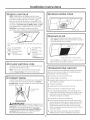
CUT HOLES
Cut holes at marked locations for duct and electrical
wiring. Forthe vertical duct, cut out 3/4" extra toward
the front of the cabinet so you can move the duct
freely when installing the hood. It may also ease
installation by cutting the hole 10W' instead of !0".
[_ RUN WIRES
Runthe electrical wires through the wall or cabinet
according to National Electrical Code and applicable
local codes.
NOTE:DO NOTturn the power on until installation is
complete.
12

Installation Instructions
[] SCREW IN PART WAY
Drive a mounting screw (from the hardware packet)
part way into each center of the narrow neck of the
keyhole slots marked on the cabinet bottom.
I-_ OPTIONAL POWER CORD
KIT JXHC1
An optional Power Cord Connection Kit, model
JXHC1, isavailable at extra cost from your
GEsupplier for installation using a standard
3-prong, grounded wall outlet. Follow the
Installation Instructions packed with the kit to
connect the power cord to the range hood.
Cabinet
]-prong
(if using cord
connection)
1¾" dia. clearance hole
for optional power
supply location
NOTE:If using optional Power Cord KitJXHC1,feed
the power cord through the hole in the top cabinet
while raising the hood. Loop any excess length of
cord and tie away with a suitable tape or tie.
I-_ FEED IN WIRES
Lift the hood into position and feed the house wiring
through the wiring knockout.
[] SECURE HOOD
Slide the hood back against the wall. Tighten the
mounting screws. Be sure the screw heads are in
the narrow neck of the keyhole slot.
NOTE:DO NOTPUSHON THEFAN BLADE.Pushing on
the blade may cause it to interfere with other hood
parts.
[] CONNECT DUCTWORK TO HOOD
(Ducted instullations only)
On 7" round installations, attach the 7" duct
with sheet metal screws through the holes in the
alignment ears.
L__.J_--- 7"round duct
Use duct tape to make joints secure and airtight.
Du
1]

Installation Instructions
[]
INSTALL LIGHT BULB
NOTE:A light bulb is not shipped with the hood.
Obtain one locally. Purchase and install a type A15
incandescent light bulb with an ordinary screw
base, not more than 60 Watts, or a type A17 or T2
Compact Fluorescent (CFL)light bulb with an ordinary
screw base, not more then 13 Watts. NOTE:Useonly
incandescentbulbsin modelsRN328,JN327and JV338.
IMPORTANT:Forinstallation,handlingand disposal
precautions,referto thefluorescentbulbpackagingliterature.
WhenusinganenergysavingbulbinyourGEhood,makesureyouuse
either:
GELongLifeEnergy
Smart"Spiral®T2
ProductCode:85383
Description:
FLE13HT2/2/SW/CD
or
GELong Life Energy
SmartS"A17
Product Code:/47486
Description:
FLEII/2/AI7XL/CD
Available at
www.gelighting.com
[] FOLLOW ELECTRICAL CODE
Complete the electrical wiring according to National
Electrical Code and local codes,
NOTE:This hood must be permanently grounded.
Connect house wiring (120 VAC)to hood wiring.
I-_ CONNECT WIRING
Connect house black to hood black wire, house white
to hood white wire and house ground under green
ground screw. Securely tighten the strain relief clamp
onto the house wiring.
Green ground
/
WARNING: IHPROPERCONNECTIONOF
ALUMINUM HOUSEWIRINGTOTHESECOPPERLEADS
CAN RESULTIN A SERIOUSPROBLEM.USEONLY
CONNECTORSDESIGNEDFORJOININGCOPPERTO
ALUMINUM AND FOLLOWTHE MANUFACTURERS
RECOMMENDEDPROCEDURECLOSELY.
14
[] REPLACE WIRING COVER
Wiring cover
[] REPLACE FILTER
Make sure fan blade turns freely and replace the
filter. NOTE:Install the metal grease filter if ducted or
the charcoal filter if recirculated.
Metal grease filter or charcoal filter
The installation is complete. Turn on power at service
panel, and test for proper operation.
TROUBLESHOOTING CHECKLIST
If the hood seems to be operating at high speed when
the control is not set on high, or if ventilation seems
inadequate, check the following:
Knockouts not removed from hood.
Damper blade not opening.
Reduced airflow because the duct istoo small or the
duct length is too long.
E_The duct is blocked.
E_ Undersized or restrictive wall or roof cap.
If the hood seems to make excessive noise:
E_ Fan may be hitting the filter. Turn off the fan and
remove the filter. Bend the filter down slightly in the
center (into a dome shape) to allow fan clearance.
Reinstall and adjust as needed.
The fan does not work but the lights do:
Switch power off at the service panel and lock the
service disconnecting means to prevent power from
being switched on accidentally. When the service
disconnecting means cannot be locked, securely
fasten a prominent warning device, such as a tag, to
the service panel.
Check the wiring connections. Seethe CONNECT
WIRINGsection in these Installation Instructions.

GE Range Hood Warranty.
All warranty service provided by our Factory Service Centers, or an
authorized Customer Care®technician. To schedule service, visit us on-line at
GEAppliances.com, or call 800.GE.CARES (800.432.2737). Please have serial
number and model number available when calling for service.
Staple your receipt here.
Proof of the original purchase
date is needed to obtain service
under the warranty.
GE Will Replace:
one Year Any part of the range hood which fails due to a defect in materials or workmanship.
From the date of the During this limited one-year warranty, GEwillalso provide, free of charge, all labor and
Origina! UrenaSe inhomeservicetoreplacethedefectivepan
[] Service trips to your home to teach you how to use
the product.
[] Improper installation, delivery or maintenance.
[] Failure of the product if it is abused, misused, or
used for other than the intended purpose or used
commercially.
[] Replacement of house fuses or resetting of circuit breakers.
[] Damage to the product caused by accident, fire, floods
or acts of God.
[] Incidental or consequential damage caused by possible
defects with this appliance.
[] Damage caused after delivery.
[] Product not accessible to provide required service.
[] Installation or service for a makeup (replacement) air
system.
EXCLUSION OF IMPLIED WARRANTIES--Your sole and exclusive remedy is product repair as provided in this
Limited Warranty. Any implied warranties, including the implied warranties of merchantability or fitness
for a particular purpose, are limited to one year or the shortest period allowed by law.
This warranty is extended to the original purchaser and any succeeding owner for products purchased for home
use within the USA. If the product is located in an area where service by a GEAuthorized Servicer is not available, you
may be responsible for a trip charge or you may be required to bring the product to an Authorized GEService Location for
service. In Alaska, the warranty excludes the cost of shipping or service calls to your home.
Some states do not allow the exclusion or limitation of incidental or consequential damages. This warranty gives
you specific legal rights, and you may also have other rights which vary from state to state. To know what your
legal rights are, consult your local or state consumer affairs office or your state's Attorney General.
Warrantor: General Electric Company. Louisville, KY 40225
15

Consumer Support.
I i
GEAppliances Website GEAppliances.com
Have a question or need assistancewith your appliance?Try the GEAppliancesWebsite 24 hours a day,
any day of the year! Forgreater convenience and faster service,you can now download Owner's Hanuals,
order parts or even schedule serviceon-line.
Schedule Service GEAppliunces.com
Expert GErepair service is only one step away from your door. Get on-line and schedule your service at
your convenience any day of the year! Or call 800.GECARES(800.432.2737) during normal business hours.
Real Life Design Studio GEAppliunces.com
GEsupports the Universal Design concept-products, services and environments that can be used by
people of all ages, sizes and capabilities. We recognize the need to design for a wide range of physical and
mental abilities and impairments. For details of GE's Universal Design applications, including kitchen design
ideas for people with disabilities, check out our Website today. Forthe hearing impaired, please call 800.TDD.
GEAC(800.833.4322).
Extended Warranties
GEAppliunces.com
Purchase a GEextended warranty and learn about special discounts that are available while your warranty
isstill in effect.You can purchase it on-line anytime, or call800.626.2224 during normal businesshours.
GEConsumer Home Serviceswill still be there after your warranty expires.
Partsand Accessories
GEAppliu ncePurts.com
Individuals qualified to servicetheir own appliances can have parts or accessoriessent directly to their homes
(VISA,HasterCard and Discovercards are accepted).Order on-line today, 24 hours every day or
by phone at 800.626.2002 during normal businesshours,
Instructions contained in this manual cover procedures to be performed byany user.Other servicinggenerally
should be referredto qualified service personnel.Caution must be exercised,since improper servicing may
cause unsafe operation.
Contact Us
GEAppliunces.com
If you are not satisfied with the serviceyou receivefrom GE,contact uson our Website with all the details
including your phone number, or write to: General Manager, Customer Relations
GEAppliances,Appliance Park
Louisville,KY40225
Register Your Appliance GEAppliances.com
Register your new appliance on-line--at your convenience! Timely product registration willallow for enhanced
communication and prompt service under the terms of your warranty, should the need arise.
You may also mail inthe pre-printed registration card included in the packing material.
Printed in China
-
 1
1
-
 2
2
-
 3
3
-
 4
4
-
 5
5
-
 6
6
-
 7
7
-
 8
8
-
 9
9
-
 10
10
-
 11
11
-
 12
12
-
 13
13
-
 14
14
-
 15
15
-
 16
16