Gladiator GAWA4PBSJG Guide d'installation
- Catégorie
- Accessoires de vélo
- Taper
- Guide d'installation

GEARTRACK
®
CHANNELS, GEARWALL
®
PANELS, HOOKS, BINS
AND BASKETS
Installation Instructions
Instructions d’installation
Instrucciones de instalación
TABLE OF CONTENTS
In U.S.A. call: 1-866-342-4089
Aux É.-U. : 1 866 342-4089
En EE.UU. Ilame al: 1-866-342-4089
W11087876A
In Canada call: 1-800-807-6777
Au Canada : 1 800 807-6777
En Canadá Ilame al: 1-800-807-6777
www.gladiatorgarageworks.com
www.gladiatorgarageworks.ca
GEARTRACK® CHANNELS AND GEARWALL® PANELS INSTALLATION SAFETY ..............................................................................................2
GEARTRACK® CHANNELS AND GEARWALL® PANELS INSTALLATION INSTRUCTIONS..............................................................................................2
Install the GearTrack® Channels.................................................................................................................................................................................4
Install the Gearwall® Panels.......................................................................................................................................................................................
.7
INSTALLATION INSTRUCTION OF HOOKS, BINS AND BASKETS ........................................................................................................................12
WARRANTY .................................................................................................................................................................................................14
TABLE DES MATIÈRES
SÛRETÉ DES INSTALLATIONS DES PROFILÉS GEARTRACK
®
ET DES PANNEAUX GEARWALL
®
..........................16
INSTRUCTIONS D’INSTALLATION DES PROFILÉS GEARTRACK
®
ET DES PANNEAUX GEARWALL
®
....................16
Installation des prolés GearTrack
®
...............................................................................................................................18
Installation des panneaux Gearwall
®
.............................................................................................................................21
INSTRUCTION D’INSTALLATION DES CROCHETS, DES BACS ET DES PANIERS .................................................... 26
GARANTIE ......................................................................................................................................................................... 28
ÍNDICE
SEGURIDAD PARA LA INSTALACIÓN DE CANALES GEARTRACK
®
Y PANELES GEARWALL
®
................................30
INSTRUCCIONES PARA LA INSTALACIÓN DE CANALES GEARTRACK
®
Y PANELES GEARWALL
®
....................... 30
Instale los canales GearTrack
®
......................................................................................................................................32
Instale los paneles Gearwall
®
........................................................................................................................................35
INSTRUCCIONES PARA LA INSTALACIÓN DE GANCHOS, RECIPIENTES Y CESTAS .............................................. 40
GARANTÍA .........................................................................................................................................................................42

2
GEARTRACK
®
CHANNELS AND GEARWALL
®
PANELS
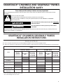
INSTALLATION SAFETY
You can be killed or seriously injured if you don't immediately
You
can be killed or seriously injured if you don't
follow
All safety messages will tell you what the potential hazard is, tell you how to reduce the chance of injury, and tell you what can
happen if the instructions are not followed.
Your safety and the safety of others are very important.
We have provided many important safety messages in this manual and on your appliance. Always read and obey all safety
messages.
This is the safety alert symbol.
This symbol alerts you to potential hazards that can kill or hurt you and others.
All safety messages will follow the safety alert symbol and either the word “DANGER” or “WARNING.”
These words mean:
follow instructions.
instructions.
DANGER
WARNING
PARTS
Parts
GearTrack
®
Channels GearWall
®
Panels
Masonry
/ Poured
Concrete
Bare Wood
Studs
Drywall Over
Wood Studs
½”(1.3 cm),
5
/
8
” (1.6 cm),
¾” (1.9 cm)
Masonry
/ Poured
Concrete
Bare Wood
Studs
Drywall Over
Wood Studs
½”(1.3 cm),
5
/
8
” (1.6 cm),
¾” (1.9 cm)
#8 x 1¹⁄
4
”(3.08 cm)*
#8 x 2” (5.08 cm)
(included)*
3
/
16
” (4.76 mm) x 1¾”
(4.45 cm)**
Construction adhesive
2” (5.08 cm) x 4” (10.16
cm) Wooden studs
¹⁄
4
” (6.3 mm) x 2³⁄
4
”
(6.99 cm)**
GEARTRACK
®
CHANNELS/GEARWALL
®
PANELS
INSTALLATION INSTRUCTIONS
Parts and Tools
■ Remove all parts and fasteners from their packaging, and dispose of/recycle all packaging materials.
■ Gather the required tools and parts before starting installation. Read and follow the instructions provided with any tools listed here.
* Use an all-weather at-head type deck screw.
** Use a at-head type masonry screw.

3
TOOLS
Tools
GearTrack
®
Channels GearWall
®
Panels
Masonry
/ Poured
Concrete
Bare Wood
Studs
Drywall Over
Wood Studs
½”(1.3 cm),
5
/
8
” (1.6 cm),
¾” (1.9 cm)
Masonry
/ Poured
Concrete
Bare Wood
Studs
Drywall Over
Wood Studs
½”(1.3 cm),
5
/
8
” (1.6 cm),
¾” (1.9 cm)
Level
Tape Measure
Cordless Drill
1/8” (3 mm) Drill Bit for
Pre-drilling holes
Stud Finder
Ac Finder
Square
Pencil
Jigsaw
Circular Saw
Chalk Line
Line Level
Hammer Drill
Caulk Gun
Chalk Line With Plumb
Bob
³⁄
16
”(4.7 mm) X 5"(12.7
cm) Masonry Drill Bit
5
/
32
”(3.9 mm) Masonry
Drill Bit
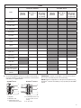
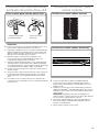
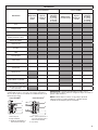
IMPORTANT: Compare screw length to electrical wire locations.
Be sure the screw will not pierce electrical wiring.
NOTE: Maximum weight limit is 75 lbs per linear ft (30.48 cm) for
GearTrack
®
Channels and 50 lbs per sq ft (2.39 kPa) for GearWall
®
Panels
■ Screw thread engagement into the wooden stud should be 1”
(2.54 cm) minimum. For drywall of a thickness not listed in the
chart above, see graphic below.
GearWall
®
Panel GearTrack
®
Channel
A
B
C
D
E
A
B
C
D
E
A. Drywall
B. Wooden stud
C. Flat-head screw in
every slot at every stud
D. 1” (2.54 cm) min. to 1¼”
(3.17 cm) max. if near
wiring
E. ¼” (6.3 mm)

4
Install the GearTrack
®
Channels
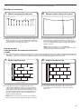
Prepare the Wall
Masonry Block / Poured Concrete Wall
■ Before installing GearTrack
®
to masonry walls, you must waterproof the walls to avoid mildew or foundation damage. Walls that
appear dry may actually become damp when enclosed by paneling. Install the channels in accordance with all local codes and
ordinances.
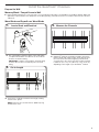
Wood Studs and Drywall over Wood Studs
■ Use a stud nder to mark the edges of the studs within
your planned installation area. Be sure to also mark the
locations of electrical wiring.
IMPORTANT: Compare screw length to electrical wiring
locations. Be sure the screw will not pierce electrical
wiring.
Stud Finder
1. Locate Studs and Electrical
■ GearTrack
®
Channels should be mounted to the wall so
that they begin and end at wooden studs. Measure from
the center of the stud at the beginning of the desired
coverage area to the center of the last wooden stud that
is within 32” (81.3 cm), 42” (106.7 cm) or 48” (121.9 cm),
depending on the length of your GearTrack
®
Channel.
2. Measure the Channels
■ If necessary, cut the rst channel to this length, making
sure the cut is square.
NOTE: Channels cut to shorter than 24” (60.96 cm) long
should not be used.
3. Cut to Length

5
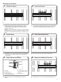
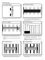
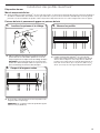
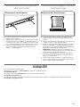
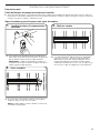
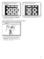
Mounting the Channels
■ Holding the channel up in the desired location, drive a
screw through the top slot groove and into the center of
the stud nearest to the middle of the channel until it is
ush with the surface.
1. Drive First Screw
■ Check that the GearTrack
®
Channel is level, and then drive
a second screw through the bottom slot groove and into
the center of the same stud as in the previous step.
2. Level the Channel
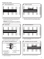
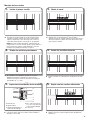
■ If splitting occurs, you may nd it necessary to predrill and
countersink the screw holes near channel ends with a
1
/
8
”
(3 mm) drill bit.
■ Make sure all screws are installed and ush with the
channel.
■ Drive a screw in every slot at every stud location.
■ Repeat this process for the next desired application area.
3. Predrill Holes
5. Inspect Screw Installation
4. Drive Remaining Screws
6. Repeat for Additional Channels
NOTE: If installing GearTrack
®
Channels on masonry block or
poured concrete, you may put construction adhesive on the
GearTrack
®
Channel before attaching it to the wall for extra
hold.
A
B
C
D
E
A
B
C
D
E
A. Drywall
B. Wooden stud
C. Flat-head screw in
every slot at every stud
D. 1” (2.54 cm) min. to 1¼”
(3.17 cm) max. if near
wiring
E. ¼” (6.3 mm)
BUBBLE LEVEL
BUBBLE LEVEL

6
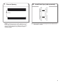
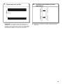
NOTE: If channels are to be used to support accessory
hooks and/or small item bins, they may be spaced in
any way desired. If channels are being used to support
Gladiator
®
Wall GearBoxes, they must be installed
18” (46 cm) apart.
■ From the front, snap the end cap onto each end of the run
of GearTrack
®
Channel.
18" (46 cm)
7. Channel Spacing
8. Install Ends Caps (sold seperately)

7
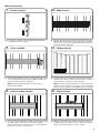
Install the GearWall
®
Panels
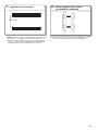
■ Snap a level chalk line at a convenient height on the wall(s).
Measure from the chalk line to the ceiling and determine the
lowest point of the ceiling along the wall.
■ Starting from the lowest point of the ceiling, measure down
to the oor. Round the measurement down to the nearest
foot and mark. Snap a level chalk line ¹⁄4” (6.3 mm) below the
mark. Repeat step for remaining walls.
NOTE: For partial wall installation, simply snap a level chalk
line at the desired height of the bottom of the wall.
1. Measure Ceiling Sag
2. Mark Bottom of Wall
Plan your Installation
■ Install the rst stud at the starting edge of the desired
coverage area to act as a guide. Drill a hole through the
stud and into the wall surface. Follow masonry screw
manufacturer’s instructions for proper installation. For best
results use a hammer drill and masonry bit.
NOTE: For extra hold, you may choose to put
construction adhesive on the stud before attaching it to
the wall.
■ Secure the stud to the wall by placing ¹⁄4” (6.3 mm) x 2³⁄4”
(6.9 cm) masonry screws every 18” (45.72 cm).
1. Mount First Stud
2. Secure First Stud
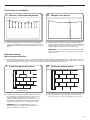
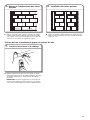
Prepare the Wall
Masonry Block / Poured Concrete Wall
■ Before you can install the panels on poured concrete or masonry block walls, you must install 2" (5.08 cm) x 4" (10.16 cm) wooden
studs to the wall with the 4" (10.16 cm) side against the wall. The wooden studs must be installed over the entire area to be covered
by the GearWall
®
panels. This provides a level surface on which to mount the panels.
B
A
A. Masonry screws
B. Wooden stud

8
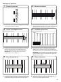
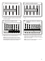
Wood Studs and Drywall over Wood Studs
■ Use a stud nder to mark the edges of the studs within
your planned installation area. Be sure to also mark the
locations of electrical wiring.
IMPORTANT: Compare screw length to electrical wiring
locations. Be sure the screw will not pierce electrical
wiring.
1. Locate Studs and Electrical
■ Use this stud as your guide. Measure 16” (40.64 cm) from
the corner and snap a vertical chalk line using a chalk line
with a plumb bob. Snap a chalk line every 16” (40.64 cm)
from this point.
■ Align the center of the stud with the chalk line. Attach the
remaining studs to the wall as you did in steps 1-2.
3. Measure Location of Remaining Studs
4. Mount Remaining Studs
16’’(40.64 cm)
16’’(40.64 cm)
Stud Finder

9
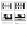
■ Panels are installed with the interlock tongue up and the
groove down.
■ Cut the rst panel to this length, making sure the cut is
square. Be sure to also cut around any windows, doors, and
outlets.
NOTE: Panels shorter than 24” (60.96 cm) long should not
be used.
■ Holding the panel up in the desired location, drive a screw
through the top slot groove and into the stud nearest to the
middle of the channel until it is ush with the surface.
■ Measure from the starting edge of the desired coverage area
to the center of the last wooden stud that is within
4 ft (1.22 m). Take note of interference with any windows,
doors, and outlets.
■ Place the panel above the horizontal chalk line applied in
the “Prepare the Wall” section. Align the panel with both the
starting edge and the horizontal chalk line.
NOTE: If installing an optional trim kit, be sure to apply the
trim at this time if mounting against an interior corner (see
“Trim Options” for details).
■ Check that the panel is level, and then drive a second screw
through the bottom slot groove and into the same stud as in
the previous step.
BUBBLE LEVEL
1. Orient the Panel
3. Cut to Length
5. Drive First Screw
2. Measure the Panel
4. Locate the Panel
6. Level the Panel
Mount the Panels

10
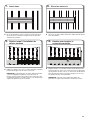
■ If splitting occurs, you may nd it necessary to predrill and
countersink the screw holes near channel ends.
■ Repeat steps 1-4 with additional panels until you reach the
opposite edge of the desired coverage area.
NOTE: If installing an optional trim kit, be sure to apply the
trim around any windows, doors, and outlets you encounter
along the way, as well as to the nal piece of the row if
mounting against an interior corner (see “Trim Options” for
details).
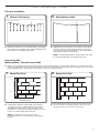
■ Drive a screw in every slot at every stud location.
■ Repeat step 5, installing each following row of wall panels
until the wall is nished. If the wall is wider than the
4 ft (1.22 m) panel, you will need to stagger the vertical panel
joints in each row with the seams at the wooden studs, as
shown.
NOTE: The nal row of panels can be rip cut lengthwise to t
the required height.
7. Predrill Holes
9. Repeat Until Row Complete
8. Drive Remaining Screws
10. Repeat Until Desired Coverage

11
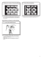
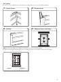
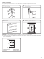
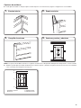
1. Interior Corner
3. End Cap
2. Exterior Corner
4. Windows, Doors, and Outlets
Trim Options
■ You may choose to apply trim to any exposed corners or edges. Below are some recommended congurations:
NOTE: The current trim options do not apply to masonry block or poured concrete wall installation.
■ Trim may also be applied around windows, doors, and outlets. Be sure to notch the trim as shown to ensure a snug t:
A
C
D
B
A. Top trim
B. Notch
C. Side trim
D. Bottom trim

12
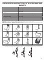
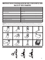
INSTALLATION INSTRUCTION OF HOOKS, BINS AND
BASKETS
Parts Maximum Weight Limit
Claw Hook, Dual Hook, Big Hook, Utility Hook 50 lbs (22.7 kg)
Horizontal Bike Hook 25 lbs (11.3 kg) for each hook and 50 lbs (22.7 kg) for the pair
Deep Hook, Wide Hook, Vertical Bike Hook 30 lbs (13.6)
Tool Hook, Cradle Hook, Twin Hook, S Hook,
Scoop Hook
25 lbs (11.3 kg)
Fishing Pole Hook 10 lbs (4.5 kg) for each hook and 20 lbs (9.1 kg) for the pair
J & L Hook, Loop Hook 5 lbs (2.2 kg)
Storage Bin Holder 25 lbs (11.3 kg) for each hook and 50 lbs (22.7 kg) for the pair
24” (60.96 cm) Mesh Basket 35 lbs (15.9 kg)
18” (45.7 cm) Wire Basket 35 lbs (15.9 kg)
Caddy Bag 25 lbs (11.3 kg)
Small Item Bin 10 lbs (4.5 kg)
IMPORTANT : Intended to be installed on Gladiator
®
Garageworks GearWall
®
panels or GearTrack
®
channels.
NOTE : Be sure the Gladiator
®
GearWall
®
panel or GearTrack
®
channel is installed with mounting screws in every slot and at every stud
location with a maximum of 24” (60.96 cm) horizontally between screws.
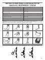
Big Hook Vertical Bike Hook S Hook L Hook
Utility Hook Tool Hook Scoop Hook Mesh Basket
Deep Hook Twin Hook J Hook Wire Basket
Hooks Installation to GearTrack
®
Channels/GearWall
®
Panels

13
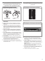
Install the Claw Hook Advanced
Bike Storage v3.0
IMPORTANT :
■ The Gladiator Claw™ Advanced Bike Storage v3.0 hook holds
either wheel of a bike.
1. Determine where you want to hang the bike. Engage the
storage hook mounting bracket into the wall slots by lifting up,
pushing toward the wall and lowering the bracket rims into the
slots.
2. Inspect the bike storage hook from the side to make sure the
mounting bracket rims are fully engaged in the slots.
3. Turn the lever lock counterclockwise to lock the storage hook
to the GearWall
®
panel or GearTrack
®
channel. Make sure the
lever lock is in the fully locked position, as shown.
4. Press the plunger until the hook arms are in the open position.
5. Lift the bike up and press the bike tire against the plunger. The
hook arms will close around the wheel. Make sure both arms
are completely closed around the wheel.
6. Remove the bike by lifting the bike up and pressing the tire
against the plunger. The hook arms will open to release the
bike wheel.
Install the Fishing Pole Hook
■ Designed to be used as a pair, the set of four shing pole
holders will support two shing poles mounted either vertically
or horizontally, as shown.
1. Install the shing pole holders into the slots in the GearWall
®
panel or GearTrack
®
channel so that distance between the
holders is one half the length of the shing pole.
NOTE : Engage the bracket rims into the slots by lifting up,
pushing toward the wall and lowering the rims into the slots.
2. Inspect the bracket from the side to ensure the rims are fully
engaged in the slots as shown.
3. Set the shing pole into the holders.
Claw Hook Advanced Bike Storage
Fishing Pole Hook (Vertical)
Fishing Pole Hook (Horizontal)
A
B
C
D
A. Lever lock
B. GearTrack
®
channel
C. Hook arm
D. Plunger

14
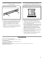
Install the Horizontal Bike Hook
■ When not in use, bike hook may be rotated to the side so it
lies at against the bracket.
1. Engage the bracket rims on the horizontal bike hook into the
slots in the GearWall
®
panel or GearTrack
®
channel by lifting
up, pushing toward the wall and lowering the rims into the
slots.
2. Inspect the bracket from the side to ensure the rims are fully
engaged in the slots as shown.
Install the Storage Bin Holder
■ Designed to be used as a pair, the bin holders will support
one storage bin up to a maximum 18 gallon size.
1. Measure the length of the storage bin 4” (10.2 cm) to
5” (12.7 cm) from the bottom.
2. Install the storage bin holders into the slots in the GearWall
®
panel or GearTrack
®
channel so that distance between the top
of the holders is the same as the length of the storage bin.
NOTE : Engage the bracket rims into the slots by lifting up,
pushing toward the wall and lowering the rims into the slots.
3. Inspect the bracket from the side to ensure the rims are fully
engaged in the slots as shown.
4. Set the storage bin into the bin holders so that the bottom
and sides are supported by the storage bin holders.
Horizontal Bike Hook
Storage Bin Holder
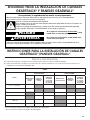
WARRANTY
For warranty information:
In U.S.A. call 1-866-342-4089 or visit our website at
www.GladiatorGW.com
In Canada call 1-800-807-6777 or visit our website at
www.gladiatorgarageworks.ca
There are many benets for registering the product. Find out more and register the product online at www.gladiatorgarageworks.com.

15
NOTES

16
SÛRETÉ DES INSTALLATIONS DES PROFILÉS
GEARTRACK
®
ET DES PANNEAUX GEARWALL
®
PIÈCES
Pièces
Prolés GearTrack
®
Panneaux GearWall
®
Mur de
maçonnerie/
béton
Poteaux de
bois nu
Mur de poteaux
de bois garni de
panneaux de gypse
½”(1,3 cm),
5
/
8
” (1,6 cm),
¾” (1,9 cm)
Mur de
maçonnerie/béton
Poteaux de
bois nu
Mur de poteaux
de bois garni de
panneaux de gypse
½”(1,3 cm),
5
/
8
” (1,6 cm),
¾” (1,9 cm)
Nº8 x 1¹⁄
4
”(3,08 cm)*
Nº 8 x 2”(5,08 cm)
(comprise)*
3
/
16
” (4,76 mm) x 1¾” (4,45
cm)**
Adhésif de construction
Poteaux de bois de 2” (5,08
cm) x 4” (10,16 cm)
¹⁄
4
” (6,3 mm) x 2³⁄
4
” (6,99
cm)**
INSTRUCTIONS D’INSTALLATION DES PROFILÉS
GEARTRACK
®
ET DES PANNEAUX GEARWALL
®
Pièces et outils
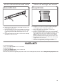
■ Retirer toutes les pièces et les attaches de leur emballage et éliminer/recycler tous les matériaux d'emballage.
■ Rassembler les outils et pièces nécessaires avant d’entreprendre l’installation. Lire et observer les instructions fournies avec chacun
des outils de la liste ci-dessous.
* Utiliser une vis pour terrasse de type à tête plate résistante aux intempéries.
* Utiliser une vis pour maçonnerie de type à tête plate.

17
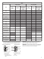
OUTILS
Outils
Prolés GearTrack
®
Panneaux GearWall
®
Mur de
maçonnerie/
béton
Poteaux de
bois nu
Mur de poteaux
de bois garni de
panneaux de gypse
½”(1,3 cm),
5
/
8
” (1,6 cm),
¾” (1,9 cm)
Mur de
maçonnerie/béton
Poteaux de
bois nu
Mur de poteaux
de bois garni de
panneaux de gypse
½”(1,3 cm),
5
/
8
” (1,6 cm),
¾” (1,9 cm)
Niveau
Ruban à mesurer
Perceuse sans l
Forets de 1/8" (3 mm) pour
avant-trous
Détecteur de poteau
Détecteur de tension CA
Carré
Crayon
Scie sauteuse
Scie circulaire
Cordeau à craie
Niveau de ligne
Perceuse à percussion
Pistolet de calfeutrage
Cordeau à craie avec l à
plomb
Foret à maçonnerie de
³⁄
16
”(4,7 mm) X 5»(12,7 cm)
Foret à maçonnerie de
5
/
32
”(3,9 mm)
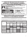
IMPORTANT: Choisir la longueur des vis en fonction de la
position des câbles électriques. Veiller à ce qu’aucune vis ne
puisse endommager l’isolant d’un câble électrique.
REMARQUE: La limite de poids maximale est de 75 lb par pied
linéaire (30,48 cm) pour les prolés GearTrack
®
et de 50 lb par
pied carré (2,39 kPa) pour les panneaux GearWall
®
.
■ La profondeur de letage des vis dans le poteau de bois devrait être
de 1” (2,54 cm) minimum Pour les panneaux de gypse d'une épaisseur
non indiquée dans le tableau ci-dessus, voir la gure ci-dessous.
Panneau GearWall
®
Panel Prolé GearTrack
®
A
B
C
D
E
A
B
C
D
E
A. Panneau de gypse
B. Poteau de bois
C. Vis à tête plate dans
chaque rainure de chaque
poteau
D. 1” (2,54 cm) min. à 1¼”
(3,17 cm) max. si près du
câblage
E. ¼” (6,3 mm)

18
Installation des prolés GearTrack
®
Préparation du mur
Mur de maçonnerie/béton
■ Avant d’installer les prolés GearTrack
®
sur un mur de maçonnerie, on doit assurer l’étanchéité du mur pour éviter toute introduction
de mildiou ou détérioration de fondation. Un mur qui semble être sec peut en fait accumuler de l’humidité après avoir été garni de
panneaux. Lors de l’installation des prolés, veiller à respecter les dispositions de tous les codes et règlements locaux en vigueur.
Poteaux de bois et panneaux de gypse sur poteaux de bois
■ Utiliser un détecteur de poteau pour marquer les bords des
poteaux dans la zone d’installation planiée. S’assurer de
marquer également les emplacements de câblage électrique.
IMPORTANT: Choisir la longueur des vis en fonction de la
position des câbles électriques. Veiller à ce qu’aucune vis ne
puisse endommager l’isolant d’un câble électrique.
Stud Finder
1. Localiser les poteaux et le câblage
■ Installer chaque prolé GearTrack
®
sur le mur de telle
manière que chaque extrémité soit en appui sur un poteau
de bois. Mesurer depuis le centre du poteau au début de
la surface à recouvrir jusqu'au centre du dernier poteau en
bois situé à moins de 32” (81,3 cm), de 42” (106,7cm) ou
de 48” (121.9 cm) selon la longueur du prolé GearTrack
®
.
2. Mesurer les prolés
■ Si nécessaire, couper la première section de prolé à cette
longueur (veiller à l’équerrage).
REMARQUE: On ne doit pas utiliser de prolé de longueur
inférieure à 24 po (60,96 cm).
3. Couper à la longueur voulue

19
Installation des prolés
■ En maintenant le prolé en place à l'emplacement désiré,
visser une vis dans la rainure supérieure et dans le centre
du poteau le plus proche du milieu du prolé jusqu'à ce
qu'elle soit au ras de la surface.
1. Visser la première vis
■ Vérier que le prolé GearTrack
®
est de niveau, puis visser
une deuxième vis à travers la rainure inférieure et dans le
centre du même poteau comme dans l'étape précédente.
2. Niveler le prolé
■ En cas de ssuration, il peut s’avérer nécessaire de percer
des avant-trous et de fraiser chaque trou de vis près des
extrémités des prolés avec un foret de
1
/
8
” (3 mm).
■ S’assurer que toutes les vis sont installées et au ras de la
surface de chaque prolé.
■ Visser une vis dans chaque rainure de chaque poteau
dans la zone d’installation.
■ Répéter ce processus pour chaque prolé apposé.
3. Avant-trous
5. Inspecter l’installation des vis
4. Visser les autres vis
6. Installation des autres prolés
REMARQUE: Si les prolés GearTrack
®
sont installés sur
un mur de maçonnerie ou de béton, mettre de l'adhésif de
construction sur le prolé GearTrack
®
avant de le xer au mur
pour une meilleure prise.
A
B
C
D
E
A
B
C
D
E
A. Panneau de gypse
B. Poteau de bois
C. Vis à tête plate dans
chaque rainure de
chaque poteau
D. 1” (2,54 cm) min. à 1¼”
(3,17 cm) max. si près
du câblage
E. ¼” (6,3 mm)
BUBBLE LEVEL
BUBBLE LEVEL

20
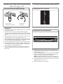
REMARQUE: Si les prolés doivent être utilisés pour
supporter les crochets d'accessoires et/ou les petits bacs
d'objets, ils peuvent être espacés au besoin. Si des prolés
sont utilisés pour supporter une armoire à outils Gladiator
®
,
ils doivent être installés à 18” (46 cm) l’un de l’autre.
■ Enclencher les embouts sur chaque extrémité du prolé
GearTrack
®
.
18" (46 cm)
7. Espacement des prolés
8. Installation des embouts (vendus
séparément)
La page est en cours de chargement...
La page est en cours de chargement...
La page est en cours de chargement...
La page est en cours de chargement...
La page est en cours de chargement...
La page est en cours de chargement...
La page est en cours de chargement...
La page est en cours de chargement...
La page est en cours de chargement...
La page est en cours de chargement...
La page est en cours de chargement...
La page est en cours de chargement...
La page est en cours de chargement...
La page est en cours de chargement...
La page est en cours de chargement...
La page est en cours de chargement...
La page est en cours de chargement...
La page est en cours de chargement...
La page est en cours de chargement...
La page est en cours de chargement...
La page est en cours de chargement...
La page est en cours de chargement...
La page est en cours de chargement...
La page est en cours de chargement...
-
 1
1
-
 2
2
-
 3
3
-
 4
4
-
 5
5
-
 6
6
-
 7
7
-
 8
8
-
 9
9
-
 10
10
-
 11
11
-
 12
12
-
 13
13
-
 14
14
-
 15
15
-
 16
16
-
 17
17
-
 18
18
-
 19
19
-
 20
20
-
 21
21
-
 22
22
-
 23
23
-
 24
24
-
 25
25
-
 26
26
-
 27
27
-
 28
28
-
 29
29
-
 30
30
-
 31
31
-
 32
32
-
 33
33
-
 34
34
-
 35
35
-
 36
36
-
 37
37
-
 38
38
-
 39
39
-
 40
40
-
 41
41
-
 42
42
-
 43
43
-
 44
44


Gladiator GAWA4PBSJG Guide d'installation
- Catégorie
- Accessoires de vélo
- Taper
- Guide d'installation
dans d''autres langues
Documents connexes
-
Gladiator GAWC4S2PLM Mode d'emploi
-
Gladiator GAWUXXBMTH Mode d'emploi
-
-
-
-
Gladiator GANA201BMS Manuel utilisateur
-
-
-
-
