Dell PowerEdge M600 Guide de démarrage rapide
- Taper
- Guide de démarrage rapide

Rack Installation Guide
Guide d'installation du rack
Rack-Installationsanleitung
ラック取り付けガイド
Guía de instalación del rack


Rack Installation Guide

Notes, Notices, and Cautions
NOTE: A NOTE indicates important information that helps you make better use
of your computer.
NOTICE: A NOTICE indicates either potential damage to hardware or loss of data
and tells you how to avoid the problem.
CAUTION: A CAUTION indicates a potential for property damage, personal injury,
or death.
____________________
Information in this document is subject to change without notice.
© 2007 Dell Inc. All rights reserved.
Reproduction in any manner whatsoever without the written permission of Dell Inc. is strictly
forbidden.
Trademarks used in this text: Dell, the DELL logo, RapidRails, and VersaRails are trademarks
of Dell Inc.
Other trademarks and trade names may be used in this document to refer to either the entities claiming
the marks and names or their products. Dell Inc. disclaims any proprietary interest in trademarks
and trade names other than its own.
August 2007 P/N DX845 Rev. A00

Contents 3
Contents
Safety Instructions . . . . . . . . . . . . . . . . . . . . 5
SAFETY: Rack Mounting of Systems
. . . . . . . . . 5
General Installation Instructions
. . . . . . . . . . . . . 6
Before You Begin
. . . . . . . . . . . . . . . . . . . 7
Important Safety Information
. . . . . . . . . . . . 7
Rack Requirements for VersaRails
. . . . . . . . . . 7
Rack Stabilizer Feet
. . . . . . . . . . . . . . . . . 8
Installation Tasks
. . . . . . . . . . . . . . . . . . . 8
Recommended Tools and Supplies
. . . . . . . . . 8
RapidRails Rack Kit Contents
. . . . . . . . . . . . 9
VersaRails Rack Kit Contents
. . . . . . . . . . . 10
Removing the Rack Doors
. . . . . . . . . . . . . . . . 11
Marking the Rack
. . . . . . . . . . . . . . . . . . . . 11
Installing the RapidRails Assemblies
. . . . . . . . . 14
Installing the VersaRails Assemblies . . . . . . . . . . 16
Installing the System in the Rack
. . . . . . . . . . . . 18
Routing and Managing Cables
. . . . . . . . . . . . . 20
Installing the Strain-Relief Bar
. . . . . . . . . . . 20
Connecting and Bundling the Cables
. . . . . . . 22
Replacing the Rack Doors
. . . . . . . . . . . . . . . 24
Index . . . . . . . . . . . . . . . . . . . . . . . . . . . . . . . 25

4 Contents

Rack Installation Guide 5
Safety Instructions
Use the following safety guidelines to ensure your own personal safety and
to help protect your system and working environment from potential damage.
For complete safety and regulatory information, see the
Product Information
Guide
that shipped with your system. Warranty information might be included
in this document or as a separate document.
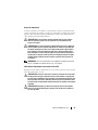
SAFETY: Rack Mounting of Systems
Observe the following precautions for rack stability and safety. Also refer to
the rack installation documentation accompanying the system and the rack for
specific caution statements and procedures.
Systems are considered to be components in a rack. Thus, "component" refers
to any system as well as to various peripherals or supporting hardware.
CAUTION: Before installing systems in a rack, install front and side stabilizers on
stand-alone racks or the front stabilizer on racks joined to other racks. Failure to
install stabilizers accordingly before installing systems in a rack could cause the
rack to tip over, potentially resulting in bodily injury under certain circumstances.
Therefore, always install the stabilizer(s) before installing components in the rack.
After installing system/components in a rack, never pull more than one component
out of the rack on its slide assemblies at one time. The weight of more than one
extended component could cause the rack to tip over and may result in serious
injury.
NOTE: Your system is safety-certified as a free-standing unit and as a component
for use in a Dell™ rack cabinet using the customer rack kit. The installation of your
system and rack kit in any other rack cabinet has not been approved by any safety
agencies. It is your responsibility to ensure that the final combination of system
and rack complies with all applicable safety standards and local electric code
requirements. Dell disclaims all liability and warranties in connection with such
combinations.
• System rack kits are intended to be installed in a rack by trained service
technicians. If you install the kit in any other rack, be sure that the rack
meets the specifications of a Dell rack.
CAUTION: Do not move racks by yourself. Due to the height and weight
of the rack, a minimum of two people should accomplish this task.

6 Rack Installation Guide
• Before working on the rack, make sure that the stabilizers are secured to
the rack, extended to the floor, and that the full weight of the rack rests
on the floor. Install front and side stabilizers on a single rack or front
stabilizers for joined multiple racks before working on the rack.
• Always load the rack from the bottom up, and load the heaviest item
in the rack first.
• Make sure that the rack is level and stable before extending a component
from the rack.
• Use caution when pressing the component rail release latches and sliding
a component into or out of a rack; the slide rails can pinch your fingers.
• Do not overload the AC supply branch circuit that provides power to the
rack. The total rack load should not exceed 80 percent of the branch
circuit rating.
• Ensure that proper airflow is provided to components in the rack.
• Do not step on or stand on any component when servicing other
components in a rack.
General Installation Instructions
This installation guide provides instructions for trained service technicians
installing one or more systems in a rack cabinet. The RapidRails™ configuration
can be installed without tools in manufacturer's rack cabinets that have square
holes; the VersaRails™ configuration can be installed in most industry-standard
rack cabinets that have square or round holes. One rack kit is required for each
system to be installed in the rack cabinet.

Rack Installation Guide 7
Before You Begin
Before you begin installing your system in the rack, carefully read "Safety
Instructions" on page 5, as well as the safety instructions found in your
Product Information Guide
for additional information.
CAUTION: When installing multiple systems in a rack, complete all of the
procedures for the current system before attempting to install the next system.
CAUTION: Rack cabinets can be extremely heavy and move easily on their
casters. They do not have brakes. Use extreme caution while moving the rack
cabinet. Retract the leveling feet when relocating the rack cabinet. Avoid long
or steep inclines or ramps where loss of cabinet control may occur. Extend
the leveling feet for support and to prevent the cabinet from rolling.
NOTE: For instructions on installing the system itself, see "Installing the System
in the Rack" on page 18.
Important Safety Information
Observe the safety precautions in the following subsections when installing
your system in the rack.
CAUTION: You must strictly follow the procedures in this document to protect
yourself as well as others who may be involved. Your system may be very large
and heavy and proper preparation and planning are important to prevent injury
to yourself and to others. This precaution becomes increasingly important when
systems are installed high up in the rack.
CAUTION: Do not install rack kit components designed for another system.
Use only the rack kit for your system. Using the rack kit for another system may
result in damage to the system and personal injury to yourself and to others.
Rack Requirements for VersaRails
NOTICE: The VersaRails rack kit is intended to be installed by trained service
technicians in a rack that meets the specifications of the Consumer Electronics
Association (CEA) standard CEA-310-E, International Electrotechnical Commission
(IEC) 297, and Deutsche Industrie Norm (DIN) 41494. One rack kit is required
for each system that is installed in a rack.

8 Rack Installation Guide
Rack Stabilizer Feet
CAUTION: Before installing systems in a rack, install front and side stabilizers on
stand-alone racks or the front stabilizer on racks joined to other racks. Failure to
install stabilizers accordingly before installing systems in a rack could cause the
rack to tip over, potentially resulting in bodily injury under certain circumstances.
Therefore, always install the stabilizer(s) before installing components in the rack.
The stabilizer feet help prevent the rack from tipping over. See the
documentation provided with the rack cabinet for instructions on installing
and anchoring the stabilizer feet.
Installation Tasks
Installing a rack kit involves performing the following tasks in their numbered
order:
1
Removing the rack doors
2
Marking the rack (if necessary)
3
Installing the rail assemblies in the rack:
• RapidRails installation
• VersaRails installation
4
Installing the system in the rack
5
Routing and managing data cables
• Installing the strain-relief bar
• Using the I/O cable enumerators
6
Replacing the rack doors
Recommended Tools and Supplies
• A #2 Phillips screwdriver
• Masking tape or a felt-tip pen, for use in marking the mounting holes
to be used
• A measuring ruler or tape measure

Rack Installation Guide 9
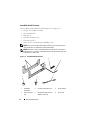
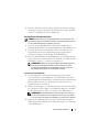
RapidRails Rack Kit Contents
The RapidRails rack kit includes the following items (see Figure 1-1):
• One pair of RapidRails assemblies
• One strain-relief bar
• Cage nuts (2)
• I/O cable enumerators (12)
• Velcro tie wraps (15)
• Four 10-32 x 0.5-inch flange-head Phillips screw
NOTE: Each rack kit contains the maximum number of Velcro tie wraps and I/O
cable enumerators that you will need for a fully loaded system.
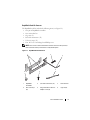
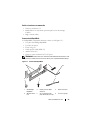
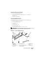
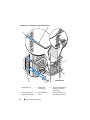
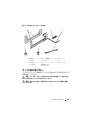
Figure 1-1. RapidRails Rack Kit Contents
1 RapidRails
assemblies
2 I/O cable enumerators (12) 3 strain-relief bar
4 Velcro tie wraps
(15)
5 flange-head 10-32 x 0.5-inch
Phillips screws (4)
6 cage nuts (2)
3
1
2
4
6
5

10 Rack Installation Guide
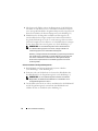
VersaRails Rack Kit Contents
The VersaRails rack kit includes the following items (see Figure 1-2):
• One pair of VersaRails assemblies
• One strain-relief bar
• Clip nuts (2)
• I/O cable enumerators (12)
• Velcro tie wraps (15)
• Twelve 10-32 x 0.5-inch flange-head Phillips screws
NOTE: Each rack kit contains the maximum number of Velcro tie wraps and I/O
cable enumerators you will need for a fully loaded system.
NOTE: Nonmetric screws are identified in this document by size and number of
threads per inch. For example, a #10 Phillips-head screw with 32 threads per inch
is identified as a 10-32 screw.
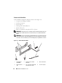
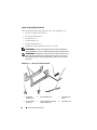
Figure 1-2. VersaRails Rack Kit Contents
1 VersaRails
assemblies
2 I/O cable enumerators (12) 3 strain-relief bar
4 Velcro tie wraps
(15)
5 flange-head 10-32 x 0.5-inch
Phillips screws (12)
6 clip nuts (2)
3
1
2
4
6
5

Rack Installation Guide 11
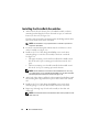
Removing the Rack Doors
See the procedures for removing doors in the documentation provided
with your rack cabinet.
CAUTION: Because of the size and weight of the rack cabinet doors,
never attempt to remove or install them by yourself.
CAUTION: Store the two doors where they will not injure someone if the doors
accidently fall over.
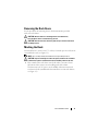
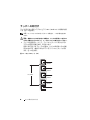
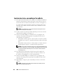
Marking the Rack
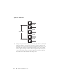
You must allow 10 U (44.45 cm or 17.5 inches) of vertical space for each system
you install in the rack (see Figure 1-3).
NOTE: Your rack may already be marked and not require this procedure.
CAUTION: If you are installing more than one system, install the rail assemblies
so that the first system is installed in the lowest available position in the rack.
1
Place a mark on the rack’s front vertical rails where you want to locate
the bottom of the system you are installing in the rack cabinet.
The bottom of each 1-U space is at the middle of the narrowest metal
area between holes (marked with a horizontal line on some rack cabinets,
see Figure 1-3).

12 Rack Installation Guide
Figure 1-3. One Rack Unit
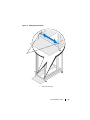
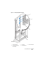
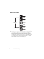
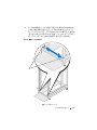
2
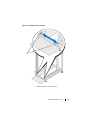
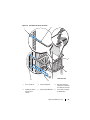
Mark the rack’s front vertical rails with a felt-tipped pen or masking tape
approximately 44.45 cm (17.5 inches) above the original mark you made
(or count up 30 holes in a rack that meets CEA-310-E standards).
(If you counted holes, place a mark just above the top hole.) This mark
or piece of tape indicates where the system’s upper edge will be located
on the vertical rails (see Figure 1-4).
1 U (44 mm or 1.75 inches)
12.7 mm (0.5 inch)
15.9 mm (0.625 inch)
15.9 mm (0.625 inch)
12.7 mm (0.5 inch)

Rack Installation Guide 13
Figure 1-4. Marking the Vertical Rails
1 tape on vertical rails
1

14 Rack Installation Guide
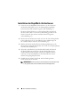
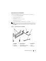
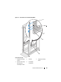
Installing the RapidRails Assemblies
1
At the front of the rack cabinet, position one of the RapidRails assemblies
so that its mounting-bracket flange fits in the appropriate location on the
rack (see Figure 1-5).
The lower mounting tab on the rail assembly’s front-mounting bracket
flange should enter the tenth hole up from the lower mark on the vertical
rails (see Figure 1-5).
2
Push the rail assembly forward until the top mounting tab enters the
square hole, which is located 4-U spaces below the upper marks or tape
you placed on the vertical rail (see Figure 1-5).
3
Next, push down on the mounting-bracket flange until the mounting tabs
seat in the square holes and the push button pops out and clicks
(see Figure 1-5).
4
At the back of the cabinet, pull back on the mounting-bracket flange until
the mounting tabs are in the appropriate holes, and then push down on
the flange until the mounting tabs seat in the square holes and the push
button pops out and clicks.
5
Repeat step 1 through step 4 for the rail assembly on the other side
of the rack.
NOTE: Ensure that the rails are mounted at the same vertical position on both
sides of the rack.

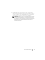
Rack Installation Guide 15
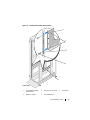
Figure 1-5. Installing the RapidRails Assemblies
1 upper mounting tab 2 push button 3 lower mounting tab
4 rail-assembly mounting-
bracket flange
5 rail assemblies (2)
1
front of rack
5
4
2
3

16 Rack Installation Guide
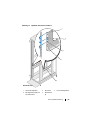
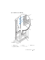
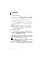
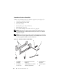
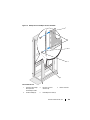
Installing the VersaRails Assemblies
1
At the front of the rack cabinet, place a VersaRails assembly so that its
mounting-bracket flange fits between the marks or tape (or numbered
location) on the rack (see Figure 1-6).
The holes on the front of the mounting bracket should align with the holes
between the marks on the front vertical rail.
NOTE: The VersaRails occupy only the lower 6-U of the 10-U space that is
required for this system.
2
Locate the round mounting hole indicated by the tooled arrow cutout
on the VersaRails (see Figure 1-6).
3
Install two 10-32 x 0.5-inch flange-head Phillips screws in the front
mounting flange to secure the rail assembly to the front vertical rail.
See Figure 1-6.
• The upper mounting screw should be installed in the middle round
hole of the 6th-U space counting up from the bottom of the 10-U
space.
• The lower mounting screw should be installed in the middle round
hole of the 1st-U space counting up from the bottom.
NOTE: The two midsection round holes on the VersaRails are for securing
your system to the rack. To assemble the VersaRails, use only the round holes
indicated by the two tooled arrow cutouts (see Figure 1-6).
4
At the back of the cabinet, pull back on the mounting-bracket flange until
the mounting holes align with their respective holes on the back vertical
rail.
5
Install two 10-32 x 0.5-inch flange-head Phillips screws in the back
mounting flange to secure the rail assembly to the back vertical rail.
6
Repeat step 1 through step 5 for the rail assembly on the other side
of the rack.
NOTE: Ensure that the rails are mounted at the same vertical position on both
sides of the rack.

Rack Installation Guide 17
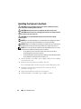
Figure 1-6. Installing the VersaRails Rail Assemblies
1 rail-assembly mounting-
bracket flange
2 tooled arrow cutouts (2) 3 vertical rails
4 Phillips screws (2) 5 rail assemblies (2)
1
front of rack
3
4
5
2

18 Rack Installation Guide
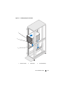
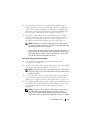
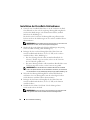
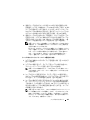
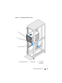
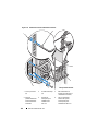
Installing the System in the Rack
CAUTION: If you are installing more than one system, install the first system
in the lowest available position in the rack.
CAUTION: Never pull more than one component out of the rack at a time.
CAUTION: Because of the size and weight of the system, never attempt to install
the system in the rack by yourself.
CAUTION: It is recommended that more than one person assist in lifting
the system.
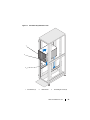
NOTICE: It is recommended that you use a lift table to aid in installing the system
in the rack, particularly if the rail assemblies are more than waist-high.
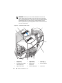
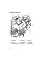
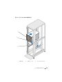
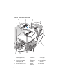
NOTICE: When you are lifting and installing your system in the rack, avoid grasping
the LCD module on the front of the system as this part is fragile. See Figure 1-7.
NOTE: If you are transporting a system that is already installed in the rack, ensure
that the two rack stabilizer mounting brackets are in place.
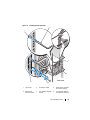
• Locate the lower clinch nut holes on either side of the rack just below
the default position for the strain-relief bar.
• To identify the default position of the strain-relief bar and the attachment points
for the stabilizer mounting brackets, see Figure 1-8.
1
Remove all blades, rear modules, power supplies, and fans before installing
your system in the rack.
2
Lift the system into position to install it in the rack.
It is recommended that more than one person assist in lifting the system.
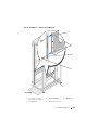
3
Guide the system into the rack and lower the system onto the rail
assemblies (see Figure 1-7).
4
Tighten the thumbscrews on the chassis front panel.
5
Reinstall the blades, rear modules, power supplies, and fans.
La page est en cours de chargement...
La page est en cours de chargement...
La page est en cours de chargement...
La page est en cours de chargement...
La page est en cours de chargement...
La page est en cours de chargement...
La page est en cours de chargement...
La page est en cours de chargement...
La page est en cours de chargement...
La page est en cours de chargement...
La page est en cours de chargement...
La page est en cours de chargement...
La page est en cours de chargement...
La page est en cours de chargement...
La page est en cours de chargement...
La page est en cours de chargement...
La page est en cours de chargement...
La page est en cours de chargement...
La page est en cours de chargement...
La page est en cours de chargement...
La page est en cours de chargement...
La page est en cours de chargement...
La page est en cours de chargement...
La page est en cours de chargement...
La page est en cours de chargement...
La page est en cours de chargement...
La page est en cours de chargement...
La page est en cours de chargement...
La page est en cours de chargement...
La page est en cours de chargement...
La page est en cours de chargement...
La page est en cours de chargement...
La page est en cours de chargement...
La page est en cours de chargement...
La page est en cours de chargement...
La page est en cours de chargement...
La page est en cours de chargement...
La page est en cours de chargement...
La page est en cours de chargement...
La page est en cours de chargement...
La page est en cours de chargement...
La page est en cours de chargement...
La page est en cours de chargement...
La page est en cours de chargement...
La page est en cours de chargement...
La page est en cours de chargement...
La page est en cours de chargement...
La page est en cours de chargement...
La page est en cours de chargement...
La page est en cours de chargement...
La page est en cours de chargement...
La page est en cours de chargement...
La page est en cours de chargement...
La page est en cours de chargement...
La page est en cours de chargement...
La page est en cours de chargement...
La page est en cours de chargement...
La page est en cours de chargement...
La page est en cours de chargement...
La page est en cours de chargement...
La page est en cours de chargement...
La page est en cours de chargement...
La page est en cours de chargement...
La page est en cours de chargement...
La page est en cours de chargement...
La page est en cours de chargement...
La page est en cours de chargement...
La page est en cours de chargement...
La page est en cours de chargement...
La page est en cours de chargement...
La page est en cours de chargement...
La page est en cours de chargement...
La page est en cours de chargement...
La page est en cours de chargement...
La page est en cours de chargement...
La page est en cours de chargement...
La page est en cours de chargement...
La page est en cours de chargement...
La page est en cours de chargement...
La page est en cours de chargement...
La page est en cours de chargement...
La page est en cours de chargement...
La page est en cours de chargement...
La page est en cours de chargement...
La page est en cours de chargement...
La page est en cours de chargement...
La page est en cours de chargement...
La page est en cours de chargement...
La page est en cours de chargement...
La page est en cours de chargement...
La page est en cours de chargement...
La page est en cours de chargement...
La page est en cours de chargement...
La page est en cours de chargement...
La page est en cours de chargement...
La page est en cours de chargement...
La page est en cours de chargement...
La page est en cours de chargement...
La page est en cours de chargement...
La page est en cours de chargement...
La page est en cours de chargement...
La page est en cours de chargement...
La page est en cours de chargement...
La page est en cours de chargement...
La page est en cours de chargement...
La page est en cours de chargement...
La page est en cours de chargement...
La page est en cours de chargement...
La page est en cours de chargement...
La page est en cours de chargement...
La page est en cours de chargement...
La page est en cours de chargement...
La page est en cours de chargement...
La page est en cours de chargement...
La page est en cours de chargement...
La page est en cours de chargement...
La page est en cours de chargement...
La page est en cours de chargement...
La page est en cours de chargement...
La page est en cours de chargement...
La page est en cours de chargement...
La page est en cours de chargement...
La page est en cours de chargement...
La page est en cours de chargement...
-
 1
1
-
 2
2
-
 3
3
-
 4
4
-
 5
5
-
 6
6
-
 7
7
-
 8
8
-
 9
9
-
 10
10
-
 11
11
-
 12
12
-
 13
13
-
 14
14
-
 15
15
-
 16
16
-
 17
17
-
 18
18
-
 19
19
-
 20
20
-
 21
21
-
 22
22
-
 23
23
-
 24
24
-
 25
25
-
 26
26
-
 27
27
-
 28
28
-
 29
29
-
 30
30
-
 31
31
-
 32
32
-
 33
33
-
 34
34
-
 35
35
-
 36
36
-
 37
37
-
 38
38
-
 39
39
-
 40
40
-
 41
41
-
 42
42
-
 43
43
-
 44
44
-
 45
45
-
 46
46
-
 47
47
-
 48
48
-
 49
49
-
 50
50
-
 51
51
-
 52
52
-
 53
53
-
 54
54
-
 55
55
-
 56
56
-
 57
57
-
 58
58
-
 59
59
-
 60
60
-
 61
61
-
 62
62
-
 63
63
-
 64
64
-
 65
65
-
 66
66
-
 67
67
-
 68
68
-
 69
69
-
 70
70
-
 71
71
-
 72
72
-
 73
73
-
 74
74
-
 75
75
-
 76
76
-
 77
77
-
 78
78
-
 79
79
-
 80
80
-
 81
81
-
 82
82
-
 83
83
-
 84
84
-
 85
85
-
 86
86
-
 87
87
-
 88
88
-
 89
89
-
 90
90
-
 91
91
-
 92
92
-
 93
93
-
 94
94
-
 95
95
-
 96
96
-
 97
97
-
 98
98
-
 99
99
-
 100
100
-
 101
101
-
 102
102
-
 103
103
-
 104
104
-
 105
105
-
 106
106
-
 107
107
-
 108
108
-
 109
109
-
 110
110
-
 111
111
-
 112
112
-
 113
113
-
 114
114
-
 115
115
-
 116
116
-
 117
117
-
 118
118
-
 119
119
-
 120
120
-
 121
121
-
 122
122
-
 123
123
-
 124
124
-
 125
125
-
 126
126
-
 127
127
-
 128
128
-
 129
129
-
 130
130
-
 131
131
-
 132
132
-
 133
133
-
 134
134
-
 135
135
-
 136
136
-
 137
137
-
 138
138
-
 139
139
-
 140
140
-
 141
141
-
 142
142
-
 143
143
-
 144
144


