Intellinet 561822 Quick Instruction Guide
- Catégorie
- Protecteurs de câbles
- Taper
- Quick Instruction Guide


2
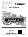
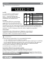
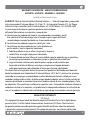
Connections & Indicators
LEDs
The LED indicators make it easier to monitor
the switch and its connections. NOTE: Ports
1 – 4 can provide power to a connected
powered device, and all powered devices
should comply with IEEE 802.3at/af.
Ports
All RJ45 ports on the switch support
Auto-MDI/MDI-X functionality, so you
can use straight or crossover UTP/STP
cables to connect the RJ45 ports to PCs, routers, hubs, other switches, etc. Cat5e/6
UTP/STP cables provide optimal performance; if a status LED doesn’t indicate a
link or activity, check the corresponding device for proper setup and operation.
Power
Use the included power cord and adapter to connect the device (on the rear
panel) to an AC outlet. Confirm that the PWR LED on the front panel is lit.
Installation
Prior to use, it is recommended that the switch be placed/positioned:
• on a level surface that can support the weight of the switch;
• with at least 25 mm (approx. 1”) of clearance for ventilation;
• away from sources of electrical noise: radios, transmitters, broadband amplifiers, etc.;
• within 100 m (approx. 328’) of network devices it’s to be connected to.
Attach the rubber feet to the bottom of each corner of the switch to increase stability.
Chassis Ground Column (Rear Panel)
Wire the grounding terminal to an earth grounding object to
protect equipment from external electrical surges.
For specifications, visit intellinetnetwork.com. Register your product at register.
intellinet-network.com/r/561822 or scan the QR code on the cover.
LED Color Status Status Description
PWR Green Off Power Off
On Power On
Link/
ACT/
SFP1
Yellow
Off No link establlished.
On Valid port connection.
Flashing Sending or receiving data.
PoE Green
Off No PD is connected to the port.
On The connected device
is receiving power.
Instructions
English

3
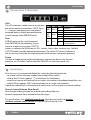
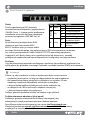
Anschlüsse & anzeigen
LED
Anzeigen Die LEDs vereinfachen
das Ablesen der Funktionen und
Anschlüsse. HINWEIS: Ports 1 – 4
können ein angeschlossenes Gerät
mit Strom versorgen, und alle mit
Strom versorgten Geräte sollten
IEEE 802.3at/af entsprechen.
Ports
Alle RJ45-Ports unterstützen Auto-MDIX Funktionalität, daher können Sie
ein Crossover- oder Nicht-Crossover UTP-/STP-Kabel verwenden, um die
RJ45-Ports mit PCs, Routern, Hubs, anderen Switchen etc. zu verbinden.
Cat5e/6- UTP/STP-Kabel bieten die beste Performance. Wenn eine LED
keineVerbindung/Aktivität anzeigt, überprüfen Sie das verbundene Gerät.
Strom
Schließen Sie das mitgelieferte Netzkabel und den Adapter an das Gerät (auf der
Rückseite) und an eine Steckdose an. Vergewissern Sie sich, dass die LED „PWR“ leuchtet.
Installation
Es wird empfohlen, den Switch vor der Nutzung folgendermaßen aufzustellen:
• auf ebenem Untergrund, der das Gewicht des Switches
• auf ebenem Untergrund mit mind. 25 mm Rundumabstand
für ausreichend Luftdurchsatz
• fern von anderen Übertragungsgeräten wie Radio, Breitbandverstärker, etc.
• max. 100 m vom zu verbindenden Netzwerkgerät entfernt.
Befestigen Sie die Gummifüße an der Unterseite jeder Ecke
des Schalters, um die Stabilität zu erhöhen.
Gehäuseerdungsschraube (Rückwand)
Verdrahten Sie die Erdungsklemme mit einem Erdungsobjekt, um
das Gerät vor externen Überspannungen zu schützen.
Die Spezifikationen finden Sie auf intellinetnetwork.com. Registrieren Sie Ihr Produkt auf
register.intellinet-network.com/r/561822 oder scannen Sie den QR-Code auf dem Deckblatt.
LED Farbe Status Bedeutung
PWR Grün Aus Ausgeschaltet
An Gerät wird mit Strom versorgt.
Link/
ACT/
SFP1
Gelb
Aus Verbindung ist nicht hergestellt.
An Verbindung ist hergestellt.
Blinkend Senden oder Empfangen von Daten.
PoE Grün Aus Es ist kein Gerät
(PD)
an den
Port angeschlossen.
An
Das angeschlossene Gerät erhält Strom.
Deutsch
Anleitung

4
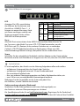
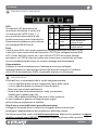
Conexiones e Indicadores
LEDs
Los LEDs hacen mas facilmonitorear el
switch y sus conexiones. NOTA: Puertos
1 – 4 pueden proveer energia a los
dispositivos, y todos los dispositivos
deben cumplir con IEEE 802.3at/af.
Puertos
Todos los puertos RJ45 del switch
soportan Auto-MDI/MDI-X, puede
utilizarse cable directo o cruzado
UTP/STP para conectar los puertos RJ45 a la PC, router, hub, otros switches, etc.
Los cables Cat5e/6 UTP/STP proporcionan un redimiento optimo; Si un LED no
indica conectividad ó actividad, compruebe las conexiones sean adecuadas.
Alimentación
Utilice el cable de alimentación y el adaptador incluidos para
conectar el dispositivo (en el panel posterior) a una toma de CA.
Confirme que el LED PWR en el panel frontal está encendido.
Instalacion
Antes de utilizarlo, se recomienda que el switch sea ubicado/fijado:
• sobre una superficie plana que pueda soportar el peso del switch
• sobre una superficie plana con al menos 25 mm de espacio libre para ventilación;
• lejos de fuentes de ruido: radios, transmisores, amplificadores de banda ancha, etc.;
• dentro de los 100 m (aprox. 328’) deben estar conectados los dispositivos de red.
Fije los pies de goma en la base de cada esquina del switch para aumentar su estabilidad.
Chasis-Tornillo de toma de tierra (panel trasero)
Conecte un cable desde la conexión de tierra a un objeto con toma de tierra, así
el equipo estará protegido frente a sobrecargas eléctricas de origen externo.
Para más especificaciones, visite intellinetnetwork.com. Registre el producto en
register.intellinet-network.com/r/561822 o escanee el código QR en la cubierta.
LED Color Estado Operación
PWR Verde Encendido Encendido
Apagado Interruptor apagado
Link/
ACT/
SFP1
Amarillo
Apagado No hay comunicación.
Encendido Válida el puerto de conexión
Parpadeando Enviando o recibiendo datos
PoE Verde
Apagado No hay ningún dispositivo
(PD) conectado al puerto.
Encendido El dispositivo conectado
recibe alimentación eléctrica.
Español
Instrucciones

5
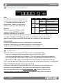
Connexions & Indicateurs
Les DEL
Les voyants d’état simplifient lire les
fonctions et lesconnexions. NOTE:
Ports 1 – 4 peuvent alimenter des
appareils connectés, qui devraient être
compatibles avec IEEE 802.3at/af.
Les ports
Tous les ports RJ45 de ce commutateur
supportent la fonctionnalité Auto-MDI/
MDI-X, donc vous pouvez utiliser des câbles
UTP/STP croisés ou non-croisés pour connecter les ports RJ45 aux PCs, routeurs, hubs,
d’autres commutateurs etc. Des câbles Cat5e/6 UTP/STP garantissent des performances
optimales; si un DEL n’indique pas d’activité, vérifiez l’appareil correspondant.
Alimentation
Connectez le cordon d’alimentation et l’adaptateur secteur fourni à
l’appareil (sur le panneau arrière) et à une prise de courant. Vérifiez
que la LED « PWR » sur le panneau avant est allumée.
Installation
Avant d’utiliser le commutateur, il est recommandé de le placer:
• sur une surface plane qui peut supporter son poids
• sur une surface plane avec un écartement de 25 mm d’autres objets pour la ventilation
• loin des appareils électriques qui peuvent être source d‘interférence (des radios etc.)
• pas plus loin que 100 m de l’appareil réseau auquel vous voudriez connecter.
Fixer les pieds en caoutchouc sous chacun des coins du
commutateur pour en améliorer la stabilité.
Vis de châssis/Mise à la terre (panneau arrière)
Câblez la borne de mise à la terre à un objet de mise à la terre pour
protéger l’équipement contre les surtensions électriques externes.
Pour obtenir des spécifications, visitez intellinetnetwork.com. Enregistrez votre produit sur
register.intellinet-network.com/r/561822 ou scannez le code QR figurant sur la couverture.
DEL Couleur Statut Indication
PWR Vert Éteint Éteindre
Allumé Appareil est alimenté.
Link/
ACT/
SFP1
Jaune
Éteinte Connexion n’est pas établie.
Allumée Connexion est établie.
Clignote En train d'émettre ou de
recevoir des données
PoE Vert Éteinte Aucun appareil (PD) n’est
connecté au port.
Allumée L’appareil connecté est alimenté.
Français
Instructions

6
Panel Przedni Urządzenia
Diody
Diody sygnalizacyjne LED ułatwiają
monitorowanie przełącznika i jego połączeń.
UWAGA: Porty 1–4 mogą zasilać podłączone
urządzenia; wszystkie zasilane urządzenia
powinny być zgodne z IEEE 802.3at / af.
Porty
Wszystkie porty przełączników RJ45
obsługują auto-krosowanie MDI/
MDI-X, możliwe więc jest użycie kabla
prostego lub krosowanego, aby połączyć porty RJ45 z komputerami, routerami,
czy innymi przełącznikami. Kable Cat5e/6 UTP/STP zapewniają optymalną
wydajność; jeśli diody statusu nie sygnalizują linku lub aktywności, sprawdź
podłączone urządzenie pod kątem poprawności konfiguracji oraz jego zasilania.
Zasilanie
Użyj dostarczonego przewodu zasilającego i zasilacza, aby podłączyć przełącznik (na
tylnej płycie) do gniazdka sieciowego. Sprawdź, czy dioda zasilania (PWR) jest włączona.
Instalacja
Zaleca się, aby urządzenie w trakcie użytkowania było umiejscowione:
• na płaskiej powierzchni, w miejscu odpowiednim do wagi urządzenia
• dla zapewnienia dobrej wentylacji w odległości co najmniej 25 mm
obudowy urządzenia od podłoża, na którym się znajduje;
• z dala od źródeł zakłóceń elektrycznych: radia, nadajniki, itp.;
• w odległości do 100 m od innych urządzeń sieciowych,
z którymi bezpośrednio jest połączony.
Podłącz gumowe podnóża od dołu na każdym rogu splittera.
Śrubka uziemienia obudowy (tylny panel)
Podłączyć gniazdo uziemienia do instalacji uziemiającej, aby
zabezpieczyć sprzęt przed zewnętrznymi skokami napięcia.
Specyfikacja techniczna dostępna jest na stronie intellinetnetwork.com.
Zarejestruj produkt na register.intellinet-network.com/r/561822 lub zeskanuj
znajdujący się na pokrywie kod QR.
Diody Kolor Stan Znaczenie
PWR Zielony Wył. Zasilanie wyłączone
Wł. Zasilanie włączone
Link/
ACT/
SFP1
Żółty
Wył Nie nawiązano połączenia.
Wł
Prawidłowe podłączenie portu.
Miga Wysyła lub odbiera dane
PoE Zielony
Wył Żadne urządzenie (PD) nie
jest podłączone do portu.
Wł Podłączone urządzenie
jest zasilane.
Polski
Instrukcje

7
Connessioni e indicatori
LEDs
Gli indicatori LED permettono di
monitorare facilmente lo switch e le
sue connessioni. NOTA: Porte 1 – 4
possono fornire alimentazione alla
periferica connessa; tutte le periferiche
alimentate dovrebbero essere conformi
allo standard IEEE 802.3at/af.
Porte
Tutte le porte RJ45 sullo switch supportano la funzionalità Auto-MDI/MDI-X, così
si possono usare sia cavi dritti che incrociati UTP/STP per collegare le porte RJ45
ai PC, router, hub, altri switch, etc. I cavi Cat5e/6 UTP/STP forniscono ottimali
prestazioni; se il LED di stato non indica una connessione o un’attività, verificare
la corrispondente periferica per un corretto settaggio e funzionamento.
Alimentazione
Utilizzare il cavo di alimentazione e l’adattatore inclusi per collegare
l’apparecchiatura (sul pannello posteriore) alla presa di corrente CA. Verificare
che il LED di alimentazione (PWR) sul pannello anteriore sia illuminato.
Installazione
Prima dell’uso, si raccomanda che lo switch venga posizionato:
• su una superficie piana che può supportare il peso dello switch
• su una superficie piana con almeno 25 mm di spazio
libero per una corrette ventilazione;
• lontano da fonti di disturbo elettrico: radio, trasmettitori,
amplificatori a banda larga, etc.;
• entro 100 m dalle periferiche di rete a cui è stato connesso.
Fissare il piedino in gomma sul fondo di ogni angolo
dello switch per migliorarne la stabilità.
Vite di messa a terra del telaio (pannello posteriore)
Collegare il terminale di messa a terra a un oggetto di messa a terra per
proteggere l’apparecchiatura da sovratensioni elettriche esterne.
Per ulteriori specifiche, visita il sito intellinetnetwork.com. Registra il tuo prodotto su register.
intellinet-network.com/r/561822 o scansiona il codice QR presente sulla copertina.
LED Colore Stato Indicazione
PWR Verde Spento Spento
Acceso Acceso
Link/
ACT/
SFP1
Giallo
Spento Nessuna connessione stabilita.
Acceso Porta di connessione valida.
Lampeggiante Invio o ricezione dati
PoE Verde
Spento Nessun dispositivo (PD)
collegato alla porta.
Acceso Il dispositivo collegato sta
ricevendo corrente.
Italiano
Istruzioni

8
WASTE ELECTRICAL & ELECTRONIC EQUIPMENT
DISPOSAL OF ELECTRIC AND ELECTRONIC EQUIPMENT
(Applicable In The European Union And Other European Countries With Separate Collection Systems)
ENGLISH: This symbol on the product or its
packaging means that this product must not
be treated as unsorted household waste. In
accordance with EU Directive 2012/19/EU
on Waste Electrical and Electronic Equipment
(WEEE), this electrical product must be disposed
of in accordance with the user’s local regulations
for electrical or electronic waste. Please dispose of
this product by returning it to your local point of
sale or recycling pickup point in your municipality.
DEUTSCH: Dieses auf dem Produkt oder der
Verpackung angebrachte Symbol zeigt an,
dass dieses Produkt nicht mit dem Hausmüll
entsorgtwerden darf. In Übereinstimmung mit
der Richtlinie 2012/19/EU des Europäischen
Parlaments und des Rates über Elektro- und
Elektronik-Altgeräte (WEEE) darf dieses
Elektrogerät nicht im normalen Hausmüll oder
dem Gelben Sack entsorgt werden. Wenn Sie
dieses Produkt entsorgen möchten, bringen
Sie es bitte zur Verkaufsstelle zurück oder zum
Recycling-Sammelpunkt Ihrer Gemeinde.
ESPAÑOL: Este símbolo en el producto o su
embalaje indica que el producto no debe tratarse
como residuo doméstico. De conformidad con la
Directiva 2012/19/EU de la UE sobre residuos de
aparatos eléctricos y electrónicos (RAEE), este
producto eléctrico no puede desecharse se con el
resto de residuos no clasificados. Deshágase de este
producto devolviéndolo a su punto de venta o a un
punto de recolección municipal para su reciclaje.
FRANÇAIS: Ce symbole sur Ie produit ou son
emballage signifie que ce produit ne doit
pas être traité comme un déchet ménager.
Conformément à la Directive 2012/19/EU
sur les déchets d’équipements électriques et
électroniques (DEEE), ce produit électrique ne
doit en aucun cas être mis au rebut sous forme
de déchet municipal non trié. Veuillez vous
débarrasser de ce produit en Ie renvoyant à son
point de vente ou au point de ramassage local
dans votre municipalité, à des fins de recyclage.
POLSKI: Jeśli na produkcie lub jego opakowaniu
umieszczono ten symbol, wówczas w czasie
utylizacji nie wolno wyrzucać tego produktu
wraz z odpadami komunalnymi. Zgodnie z
Dyrektywą Nr 2012/19/EU w sprawie zużytego
sprzętu elektrycznego i elektronicznego (WEEE),
niniejszego produktu elektrycznego nie wolno
usuwać jako nie posortowanego odpadu
komunalnego. Prosimy o usuniecie niniejszego
produktu poprzez jego zwrot do punktu zakupu
lub oddanie do miejscowego komunalnego punktu
zbiórki odpadów przeznaczonych do recyklingu.
ITALIANO: Questo simbolo sui prodotto o
sulla relativa confezione indica che il prodotto
non va trattato come un rifiuto domestico. In
ottemperanza alla Direttiva UE 2012/19/EU sui
rifiuti di apparecchiature elettriche ed elettroniche
(RAEE), questa prodotto elettrico non deve
essere smaltito come rifiuto municipale misto.
Si prega di smaltire il prodotto riportandolo al
punto vendita o al punto di raccolta municipale
locale per un opportuno riciclaggio.

9
WARRANTY INFORMATION • GARANTIEINFORMATIONEN •
GARANTÍA • GARANTIE • GWARANCJI • GARANZIA
intellinetnetwork.com
EN MÉXICO: Póliza de Garantía Intellinet Network Solutions — Datos del importador y responsable
ante el consumidor IC Intracom México, S.A.P.I. de C.V. • Av. Interceptor Poniente # 73, Col. Parque
Industrial La Joya, Cuautitlán Izcalli, Estado de México, C.P. 54730, México. • Tel. (55)1500-4500
La presente garantía cubre los siguientes productos contra cualquier
defecto de fabricación en sus materiales y mano de obra.
A Garantizamos los productos de limpieza, aire comprimido y consumibles, por 60
dias a partir de la fecha de entrega, o por el tiempo en que se agote totalmente
su contenido por su propia función de uso, lo que suceda primero.
B Garantizamos los productos con partes móviles por 3 años.
C Garantizamos los demás productos por 5 años (productos sin
partes móviles), bajo las siguientes condiciones:
1 Todos los productos a que se refiere esta garantía, ampara su
cambio físico, sin ningún cargo para el consumidor.
2 El comercializador no tiene talleres de servicio, debido a que los productos que se garantizan
no cuentan con reparaciones, ni refacciones, ya que su garantía es de cambio físico.
3 La garantía cubre exclusivamente aquellas partes, equipos o sub-ensambles que
hayan sido instaladas de fábrica y no incluye en ningún caso el equipo adicional o
cualesquiera que hayan sido adicionados al mismo por el usuario o distribuidor.
Para hacer efectiva esta garantía bastará con presentar el producto al distribuidor en el domicilio
donde fue adquirido o en el domicilio de IC Intracom México, S.A.P.I. de C.V., junto con los accesorios
contenidos en su empaque, acompañado de su póliza debidamente llenada y sellada por la casa
vendedora (indispensable el sello y fecha de compra) donde lo adquirió, o bien, la factura o ticket de
compra original donde se mencione claramente el modelo, número de serie (cuando aplique) y fecha
de adquisición. Esta garantía no es válida en los siguientes casos: Si el producto se hubiese utilizado en
condiciones distintas a las normales; si el producto no ha sido operado conforme a los instructivos de
uso; o si el producto ha sido alterado o tratado de ser reparado por el consumidor o terceras personas.
REGULATORY STATEMENTS
FCC Class A
This equipment has been tested and found to comply with the limits for a Class A digital device,
pursuant to Part 15 of the Federal Communications Commission (FCC) Rules. These limits are
designed to provide reasonable protection against harmful interference when the equipment
is operated in a commercial environment. This equipment generates, uses and can radiate radio

10
frequency energy, and if not installed and used in accordance with the instruction manual may
cause harmful interference to radio communications. Operation of this equipment in a residential
area is likely to cause harmful interference, in which case the user will be required to correct
the interference at his own expense. Any changes or modifications made to this equipment
without the approval of the manuafacturer could result in the product not meeting the Class
A limits, in which case the FCC could void the user’s authority to operate the equipment.
CE
ENGLISH : This device complies with the requirements of CE 2014/30/EU and/
or 2014/35/EU. The Declaration of Conformity for is available at:
DEUTSCH : Dieses Gerät enspricht der CE 2014/30/EU und / oder 2014/35/EU. Die
Konformitätserklärung für dieses Produkt finden Sie unter:
ESPAÑOL : Este dispositivo cumple con los requerimientos de CE 2014/30/EU y / o
2014/35/EU. La declaración de conformidad esta disponible en:
FRANÇAIS : Cet appareil satisfait aux exigences de CE 2014/30/EU et / ou
2014/35/EU. La Déclaration de Conformité est disponible à:
POLSKI : Urządzenie spełnia wymagania CE 2014/30/EU I / lub 2014/35/EU. Deklaracja
zgodności dostępna jest na stronie internetowej producenta:
ITALIANO : Questo dispositivo è conforme alla CE 2014/30/EU e / o 2014/35/EU.
La dichiarazione di conformità è disponibile al:
support.intellinet-network.com/barcode/561822
North America
IC Intracom America
550 Commerce Blvd.
Oldsmar, FL 34677
USA
Asia & Africa
IC Intracom Asia
4-F, No. 77, Sec. 1, Xintai 5th Rd.
Xizhi Dist., New Taipei City 221
Taiwan
Europe
IC Intracom Europe
Löhbacher Str. 7, D-58553
Halver
Germany
All trademarks and trade names are the property of their respective owners. © IC Intracom. All rights
reserved. Intellinet Network Solutions is a trademark of IC Intracom, registered in the U.S. and other countries.

11
NOTES

-
 1
1
-
 2
2
-
 3
3
-
 4
4
-
 5
5
-
 6
6
-
 7
7
-
 8
8
-
 9
9
-
 10
10
-
 11
11
-
 12
12


Intellinet 561822 Quick Instruction Guide
- Catégorie
- Protecteurs de câbles
- Taper
- Quick Instruction Guide
dans d''autres langues
- italiano: Intellinet 561822
- English: Intellinet 561822
- español: Intellinet 561822
- Deutsch: Intellinet 561822
- polski: Intellinet 561822
Documents connexes
-
Intellinet 561723 Quick Instruction Guide
-
-
Intellinet 560764 Quick Instruction Guide
-
Intellinet 561877 Quick Instruction Guide
-
Intellinet 560993 Mode d'emploi
-
Intellinet 561938 Quick Instruction Guide
-
-
Intellinet 508827 Quick Instruction Guide
-
-
Intellinet 561907 Mode d'emploi
