
CAM45
Rear View Video Camera
Installation and Operating Manual . . . . . . 9
Rückfahrvideokamera
Montage- und Bedienungsanleitung . . . 20
Caméra vidéo de recul
Instructions de montage et de service . . 31
Cámara de vídeo de marcha atrás
Instrucciones de montaje y de uso . . . . .42
Câmara de marcha-atrás
Instruções de montagem e manual de
instruções . . . . . . . . . . . . . . . . . . . . . . . . . 53
Videocamera per la retromarcia
Istruzioni di montaggio e d’uso . . . . . . . . 63
Achteruitrijvideocamera
Montagehandleiding en
gebruiksaanwijzing. . . . . . . . . . . . . . . . . . 74
Bakvideokamera
Monterings- og betjeningsvejledning. . . 85
Backningsvideokamera
Monterings- och bruksanvisning . . . . . . . 95
Ryggevideokamera
Monterings- og bruksanvisning . . . . . . . 105
Peruutusvideokamera
Asennus- ja käyttöohje. . . . . . . . . . . . . . .115
Видеокамера заднего вида
Инструкция по монтажу
и эксплуатации. . . . . . . . . . . . . . . . . . . . 126
Kamera cofania
Instrukcja montażu i obsługi . . . . . . . . . 137
Cúvacia kamera
Návod na montáž a uvedenie
do prevádzky . . . . . . . . . . . . . . . . . . . . . 148
Couvací kamera
Návod k montáži a obsluze . . . . . . . . . . 158
Tol a t ó kam e r a
Szerelési és használati útmutató . . . . . . 168
EN
DE
FR
ES
PT
IT
NL
DA
SV
NO
FI
RU
PL
SK
CS
HU
DRIVING SUPPORT
PERFECTVIEW
CAM45-IO-16s.book Seite 1 Donnerstag, 1. März 2018 10:19 10

CAM45-IO-16s.book Seite 2 Donnerstag, 1. März 2018 10:19 10

CAM45
3
1 2
3
4
7 8 9
5
6
10 11 12
1
CAM45-IO-16s.book Seite 3 Donnerstag, 1. März 2018 10:19 10

CAM45
4
2
3
4
5
6
7
CAM45-IO-16s.book Seite 4 Donnerstag, 1. März 2018 10:19 10

CAM45
5
1
3 4
2
8
3
2
1
9
CAM45-IO-16s.book Seite 5 Donnerstag, 1. März 2018 10:19 10

CAM45
6
90°
0
a
1.
2.
b
c
d
e
CAM45-IO-16s.book Seite 6 Donnerstag, 1. März 2018 10:19 10

CAM45
7
~50°
f
AB
1.
2.
1.
g
h
A
B
i
CAM45-IO-16s.book Seite 7 Donnerstag, 1. März 2018 10:19 10

CAM45
8
1.
2.
j
CAM45-IO-16s.book Seite 8 Donnerstag, 1. März 2018 10:19 10

CAM45
EN
9
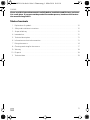
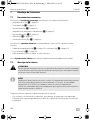
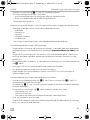
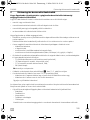
Please read this instruction manual carefully before installation and first use, and store
it in a safe place. If you pass on the product to another person, hand over this instruc-
tion manual along with it.
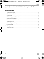
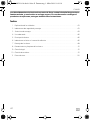
Table of contents
1 Explanation of symbols. . . . . . . . . . . . . . . . . . . . . . . . . . . . . . . . . . . . . . . . . . . . . . . . . . . . . . 10
2 Safety and installation instructions . . . . . . . . . . . . . . . . . . . . . . . . . . . . . . . . . . . . . . . . . . . . . 10
3 Scope of delivery . . . . . . . . . . . . . . . . . . . . . . . . . . . . . . . . . . . . . . . . . . . . . . . . . . . . . . . . . . 12
4 Intended use . . . . . . . . . . . . . . . . . . . . . . . . . . . . . . . . . . . . . . . . . . . . . . . . . . . . . . . . . . . . . . 12
5 Technical description . . . . . . . . . . . . . . . . . . . . . . . . . . . . . . . . . . . . . . . . . . . . . . . . . . . . . . . 13
6 Information on electrical connection. . . . . . . . . . . . . . . . . . . . . . . . . . . . . . . . . . . . . . . . . . . 13
7 Fitting the camera . . . . . . . . . . . . . . . . . . . . . . . . . . . . . . . . . . . . . . . . . . . . . . . . . . . . . . . . . . 14
8 Cleaning and caring for the camera. . . . . . . . . . . . . . . . . . . . . . . . . . . . . . . . . . . . . . . . . . . . 17
9 Warranty . . . . . . . . . . . . . . . . . . . . . . . . . . . . . . . . . . . . . . . . . . . . . . . . . . . . . . . . . . . . . . . . . 18
10 Disposal. . . . . . . . . . . . . . . . . . . . . . . . . . . . . . . . . . . . . . . . . . . . . . . . . . . . . . . . . . . . . . . . . . 18
11 Technical data. . . . . . . . . . . . . . . . . . . . . . . . . . . . . . . . . . . . . . . . . . . . . . . . . . . . . . . . . . . . . 19
CAM45-IO-16s.book Seite 9 Donnerstag, 1. März 2018 10:19 10

Explanation of symbols CAM45
EN
10
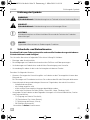
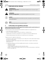
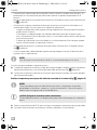
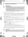
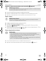
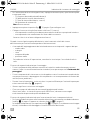
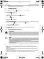
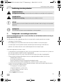
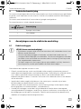
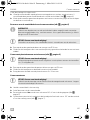
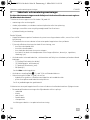
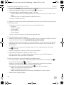
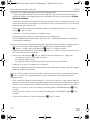
1 Explanation of symbols
!
!
A
I
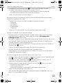
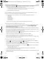
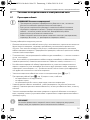
2 Safety and installation instructions
Please observe the prescribed safety instructions and stipulations from the vehicle
manufacturer and service workshops.
The manufacturer accepts no liability for damage in the following cases:
•
Faulty assembly or connection
•
Damage to the product resulting from mechanical influences and excess voltage
•
Alterations to the product without express permission from the manufacturer
•
Use for purposes other than those described in the operating manual
Please note the following:
•
To prevent the risk of short circuits, always disconnect the negative terminal of the vehicle's
electrical system before working on it.
If the vehicle has an additional battery, its negative terminal should also be disconnected.
•
Inadequate supply cable connections could result in short circuits, causing:
–Cable fires
– The airbag being triggered
– Damage to electronic control equipment
– Electrical malfunctions (indicators, brake light, horn, ignition, lights)
•
When working on the following cables, only use insulated cable terminals, plugs and flat
sockets:
– 30 (direct supply from positive battery terminal)
–15 (connected positive terminal, behind the battery)
– 31 (return cable from the battery, earth)
– 58 (reversing light)
Do not use porcelain wire connectors.
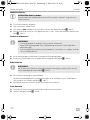
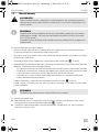
WARNING!
Safety instruction: Failure to observe this instruction can cause fatal or serious injury.
CAUTION!
Safety instruction: Failure to observe this instruction can lead to injury.
NOTICE!
Failure to observe this instruction can cause material damage and impair the function
of the product.
NOTE
Supplementary information for operating the product.
CAM45-IO-16s.book Seite 10 Donnerstag, 1. März 2018 10:19 10

CAM45 Safety and installation instructions
EN
11
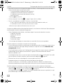
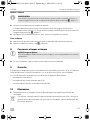
•
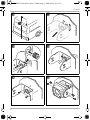
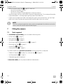
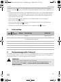
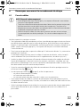
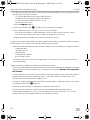
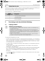
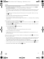
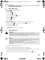
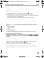
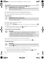
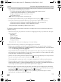
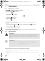
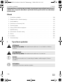
Use a crimping tool (fig. 1 10, page 3) to connect the cables.
•
Screw the cable when connecting cable 31 (earth).
– Screw on the cable using a cable terminal and serrated washer to one of the vehicle's earth
bolts or
– screw the cable to the bodywork using a cable terminal and a self-tapping screw.
Make sure there is a good earth connection.
If you disconnect the negative terminal of the battery, all data stored in the volatile memories will
be lost.
•
The following data must be reset, depending on the vehicle equipment options:
–Radio code
– Vehicle clock
–Timer
– On-board computer
– Seat position
You can find instructions for making these settings in the operating manual.
Observe the following installation instructions:
•
Secure the parts of the camera which are installed in the vehicle in such a way that they cannot
become loose under any circumstances (sudden braking, accidents) and cause injuries to the
occupants of the vehicle.
•
Secure any parts of the system concealed by the bodywork in such a manner that they cannot
be come loose or damage other parts or cables, or impair vehicle functions (steering, pedals,
etc.).
•
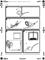
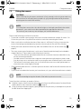
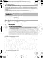
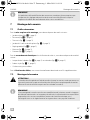
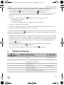
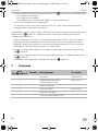
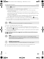
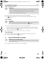
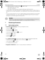
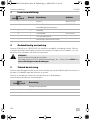
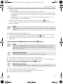
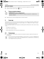
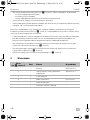
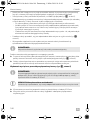
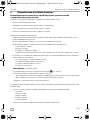
To prevent damage when drilling, make sure there is sufficient space on the other side for the
drill head to come out (fig. 2, page 4).
•
Deburr all drill holes and treat them with a rust-protection agent.
•
Always follow the safety instructions of the vehicle manufacturer.
Some work (e.g. on retention systems such as the AIRBAG etc.) may only be performed by
qualified specialists.
Observe the following instructions when working with electrical parts:
•
When testing the voltage in electrical cables, only use a diode test lamp (fig. 1 8, page 3) or
a voltmeter (fig. 1 9, page 3).
Test lamps with a bulb (fig. 1 12, page 3) consume voltages which are too high and can
damage the vehicle's electronic system.
•
When making electrical connections, (fig. 3, page 4), ensure that:
– they are not kinked or twisted
– they do not rub on edges
– they are not laid in sharp-edged ducts without protection.
•
Insulate all connections.
CAM45-IO-16s.book Seite 11 Donnerstag, 1. März 2018 10:19 10

Scope of delivery CAM45
EN
12
•
Secure the cables against mechanical wear by using cable binders or insulating tape,
for example on existing cables.
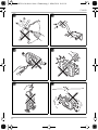
The camera is watertight. However, the seals on the camera cannot withstand a high-pressure
cleaner (fig. 4, page 4). Therefore, you should observe the following instructions when handling
the camera:
•
People (including children) whose physical, sensory or mental capacities or whose lack of
experience or knowledge prevent them from using this product safely should not use it without
the supervision or instruction of a responsible person.
•
Do not open the camera, as this impairs the leak tightness and the function of the camera
(fig. 5, page 4).
•
Do not pull at the cables, as this impairs the tightness and the function of the camera (fig. 6,
page 4).
•
The camera is not suitable for use under water (fig. 7, page 4)!
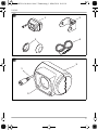
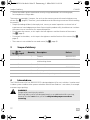
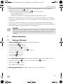
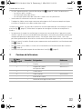
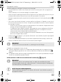
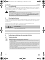
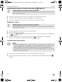
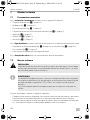
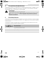
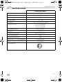
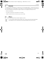
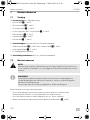
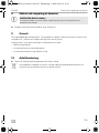
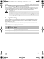
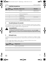
3Scope of delivery
4Intended use
The CAM45 camera (ref. no. 9600000523) is designed primarily for use in vehicles. It can be used
in video systems to observe the space around the vehicle from the driver's seat when, for example
manoeuvring or parking.
!
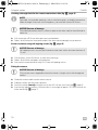
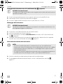
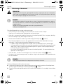
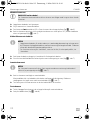
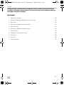
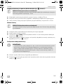
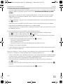
No. in
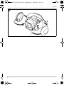
fig. 8, page 5
Quantity Description Ref. no.
1 1 Camera 9600000523
21Camera bracket
with bushing sleeve
9600000571
32Side cover –
4 1 System cable 9102200141
–1Fastening material –
– 1 Installation and operating manual –
WARNING!
Danger of personal injury by vehicle.
Reversing video systems are designed merely as an additional aid for reversing,
however this does not relieve you of the duty to take proper care when
reversing.
CAM45-IO-16s.book Seite 12 Donnerstag, 1. März 2018 10:19 10

CAM45 Technical description
EN
13
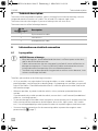
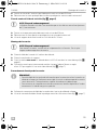
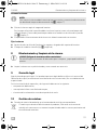
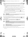
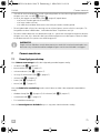
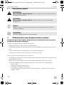
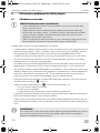
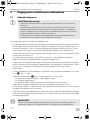
5 Technical description
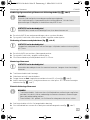
The camera with integrated microphone, which is encased in an aluminium housing, transmits
image and sound to a monitor via a cable. The infrared LEDs improve night vision.
The camera transmits the image as if you were looking in the rear-view mirror.
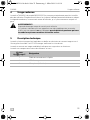
The camera consists of the following elements:
6 Information on electrical connection
6.1 Laying cables
A
Therefore, please observe the following instructions:
•
As far as possible, use original ducts for laying the cables, or other suitable options such as
panelling edges, ventilation grilles or dummy plugs. If no openings are available, you must drill
holes for the cables. Check beforehand that there is sufficient space on the other side for the
drill head to emerge.
•
Wherever possible, lay cables inside the vehicle, as they are better protected there than
outside.
If you do need to lay a cable outside the vehicle, ensure that it is well fastened (use additional
cable ties, insulating tape etc.).
•
To prevent damage to the cables when laying them, ensure that they are far enough away from
hot or moving vehicle components (exhaust pipes, drive shafts, light systems, fans, heaters,
etc.). Use corrugated piping or other protective materials to protect against mechanical wear.
•
Screw on the plug connections for the connecting cables to protect them against water
penetration (fig. g, page 7).
No. in
fig. 9, page 5
Description
16-pin connection cable
2 Infrared LEDs
3 Microphone (rear side)
NOTICE! Beware of damage
•
When drilling holes, check beforehand that there is sufficient space on the other
side for the drill head to come out.
•
Cables and connections that are not properly installed will cause malfunctions or
damage to components. Correct installation of cables and connections ensures
lasting and trouble-free operation of the retrofitted components.
•
The cables may not be exposed for long periods to solvents such as benzene, since
solvents can damage the cable.
CAM45-IO-16s.book Seite 13 Donnerstag, 1. März 2018 10:19 10

Fitting the camera CAM45
EN
14
•
When laying the cables (fig. 3, page 4), make sure:
– they are not kinked or twisted
– they do not rub on edges
– they are not routed in sharp-edged ducts without protection.
•
Attach the cables securely in the vehicles to prevent tripping hazards. This can be performed by
using cable binders, insulating tape or gluing in place with adhesives.
•
Protect every through-hole made in the bodywork against water penetration, e.g. by using a
cable with a sealant and by spraying the cable and the cable sleeve with sealant.
I
7 Fitting the camera
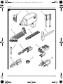
7.1 Tools required
For installation and assembly, you will need the following tools:
•
Drill bit set (fig. 1 1, page 3)
•
Electric drill (fig. 1 2, page 3)
•
Screwdriver (fig. 1 3, page 3)
•
Set of ring or open-ended spanners (fig. 1 4, page 3)
•
Measuring ruler (fig. 1 5, page 3)
•
Hammer (fig. 1 6, page 3)
•
Centre punch (fig. 1 7, page 3)
To establish and test the electrical connection, the following tools are required:
•
Diode test lamp (fig. 1 8, page 3) or voltmeter (fig. 1 9, page 3)
•
Insulating tape (fig. 1 11, page 3)
•
Cable bushing sleeves (optional)
To fasten the cables you may require additional cable binders.
NOTE
Only start sealing through-holes when you have completed all installation work on the
camera and have laid the required cable lengths.
CAM45-IO-16s.book Seite 14 Donnerstag, 1. März 2018 10:19 10

CAM45 Fitting the camera
EN
15
7.2 Fitting the camera
!
I
Observe the following installation instructions:
•
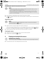
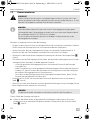
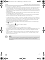
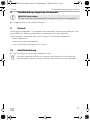
To provide a suitable viewing angle, the camera must be attached at a height of at least 2 m.
Ensure that you have a firm place from which to work when mounting the camera.
•
Make sure that the installation location of the camera is sufficiently firm (e.g. to prevent the
camera from being knocked down by branches that may brush the roof of the vehicle).
•
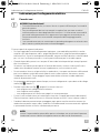
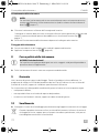
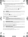
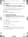
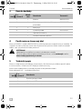
Mount the camera bracket horizontally and in the middle of the rear of the vehicle (fig. 0,
page 6).
•
The most secure type of attachment is with screws fitted through the body (not included in
scope of delivery). Please observe the following instructions:
– There must be sufficient space behind the chosen installation location to be able to carry
out the mounting procedure.
– Suitable measures must be taken to prevent water penetrating through any holes made
(e.g. by using screws and sealant and/or spraying the outer attachment parts with sealant).
– The location on the body where you wish to attach the camera must be rigid enough to
allow the camera to be tightly fastened.
•
Check beforehand that there is sufficient space on the other side for the drill head to come out
(fig. 2, page 4).
•
If you are not sure about the location you have chosen, ask your vehicle manufacturer or dealer.
I
To perform the installation, proceed as follows:
➤ Hold the camera at the chosen location and mark at least two different points for the drill holes
and the duct for the connection cable (fig. a, page 6).
➤ Using a hammer and centre punch, gently pre-punch the previously marked points to prevent
the drill head from slipping off.
CAUTION!
Select a location for the camera and attach it firmly enough so that it cannot under any
circumstances fall off and injure bystanders (e.g. by being knocked off by branches
brushing over the roof of the vehicle).
NOTE
If installing the camera alters the vehicle height or the length specified in the vehicle
documents, your vehicle must be inspected by the appropriate authorities.
This authority must note any such changes your vehicle documents.
NOTE
We recommend greasing the threads of the bolts to prevent corrosion.
CAM45-IO-16s.book Seite 15 Donnerstag, 1. März 2018 10:19 10

Fitting the camera CAM45
EN
16
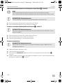
Creating a through-hole for the camera connection cable (fig. b, page 6)
I
A
➤ Drill a hole with a Ø 16 mm at the previously marked duct.
➤ Deburr all drill holes that have been made in the sheet metal and apply rust-protection.
Screw on camera using self-tapping screws (fig. c, page 6)
A
➤ Drill the holes, with a Ø of 4 mm, at each of the markings.
➤ Deburr all drill holes and apply rust-protection.
➤ Screw on the camera bracket using 5 x 20 mm self-tapping screws.
Fitting the camera
A
➤ Guide the camera cable into the vehicle interior.
➤ Slide the camera into the camera bracket.
➤ Fasten the camera loosely using the two screws M3 x 6 mm in the slots (fig. e, page 6).
➤ Provisionally align the camera, so that the lens is at an angle of approx. 50° to the vertical axis
of the vehicle (fig. f, page 7).
NOTE
If possible, use available openings, such as ventilation grilles, to feed the connection
cables through. If there are no existing ducts, you must drill a hole of Ø 16 mm.
NOTICE! Beware of damage
Check beforehand that there is sufficient space on the other side for the drill head to
come out.
NOTICE! Beware of damage
Self-tapping screws may only be fastened to steel metal with a minimum thickness of
1.5 mm.
NOTICE! Beware of damage
Only use the screws supplied to mount the camera. Longer screws will damage the
camera.
CAM45-IO-16s.book Seite 16 Donnerstag, 1. März 2018 10:19 10

CAM45 Cleaning and caring for the camera
EN
17
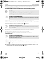
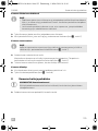
Establishing the electrical connection for the camera
I
➤ Insert the camera cable plug into the socket for the extension cable.
➤ Screw on the plug connection of the connecting cables to protect against water penetration
(fig. g, page 7).
Aligning the camera
I
➤ Align the camera using the image on the monitor to help you:
The monitor image should show the rear or the bumper of the vehicle at the bottom edge of
the screen. The middle of the bumper should be in the middle of the screen (fig. i, page 7).
➤ Check the function of the camera after you have connected it to a monitor.
Fastening the camera
➤ Tighten the two fastening screws in the slots on the monitor bracket.
➤ Fit side covers into place (fig. j, page 8).
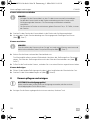
8 Cleaning and caring for the camera
A
➤ Clean the camera with a soft, damp cloth from time to time.
NOTE
•
Lay the camera cable so that, should you need to remove the camera, you can
access the plug connection between the
camera and the extension cable easily. This greatly facilitates the disassembly.
•
To minimise corrosion in the plug, apply a small amount of grease, such as pin
grease, in one of the plugs.
NOTE
To do this you must first install and electrically connect a monitor (see schematic
connection diagram fig. h, page 7).
NOTICE! Beware of damage
Do not use any sharp or hard objects for cleaning since they may damage the device.
CAM45-IO-16s.book Seite 17 Donnerstag, 1. März 2018 10:19 10

Warranty CAM45
EN
18
9Warranty
The statutory warranty period applies. If the product is defective, please contact the
manufacturer's branch in your country (see the back of the instruction manual for the addresses) or
your retailer.
For repair and guarantee processing, please send the following items:
•
Defect components
•
A copy of the receipt with purchasing date
•
A reason for the claim or description of the fault
10 Disposal
➤ Place the packaging material in the appropriate recycling waste bins wherever possible.
M
If you wish to finally dispose of the product, ask your local recycling centre or specialist
dealer for details about how to do this in accordance with the applicable disposal
regulations.
CAM45-IO-16s.book Seite 18 Donnerstag, 1. März 2018 10:19 10

CAM45 Technical data
EN
19
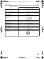
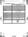
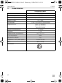
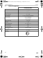
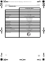
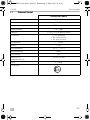
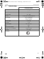
11 Technical data
PerfectView CAM45
Ref. no.: 9600000523
Image sensor: 1/4" CCD
Pixels: Approx. 250000 pixels
Video standard: PAL, 1 Vpp
Sensitivity: < 1 Lux / 0 Lux with infrared LEDs
Viewing angle: Approx. 120° diagonal
Approx. 80° horizontal
Approx. 65° vertical
Operating voltage: 11 to 16 Vg
Consumption: 1.2 W
Operating temperature: –20 °C to +70 °C
Protection class: IP69k
Vibration resistance: 6g
Dimensions W x H x D
(with bracket):
78 x 60 x 50 mm
Weight: Approx. 0.18 kg
Certification:
8
CAM45-IO-16s.book Seite 19 Donnerstag, 1. März 2018 10:19 10

CAM45
DE
20
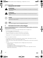
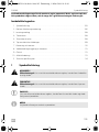
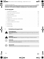
Bitte lesen Sie diese Anleitung vor Einbau und Inbetriebnahme sorgfältig durch und
bewahren Sie sie auf. Geben Sie sie im Falle einer Weitergabe des Produktes an den
Nutzer weiter.
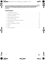
Inhaltsverzeichnis
1 Erklärung der Symbole. . . . . . . . . . . . . . . . . . . . . . . . . . . . . . . . . . . . . . . . . . . . . . . . . . . . . . 21
2 Sicherheits- und Einbauhinweise. . . . . . . . . . . . . . . . . . . . . . . . . . . . . . . . . . . . . . . . . . . . . . 21
3 Lieferumfang . . . . . . . . . . . . . . . . . . . . . . . . . . . . . . . . . . . . . . . . . . . . . . . . . . . . . . . . . . . . . .23
4 Bestimmungsgemäßer Gebrauch . . . . . . . . . . . . . . . . . . . . . . . . . . . . . . . . . . . . . . . . . . . . .23
5 Technische Beschreibung . . . . . . . . . . . . . . . . . . . . . . . . . . . . . . . . . . . . . . . . . . . . . . . . . . .24
6 Hinweise zum elektrischen Anschluss . . . . . . . . . . . . . . . . . . . . . . . . . . . . . . . . . . . . . . . . . .24
7 Kamera montieren . . . . . . . . . . . . . . . . . . . . . . . . . . . . . . . . . . . . . . . . . . . . . . . . . . . . . . . . .25
8 Kamera pflegen und reinigen. . . . . . . . . . . . . . . . . . . . . . . . . . . . . . . . . . . . . . . . . . . . . . . . .28
9 Gewährleistung . . . . . . . . . . . . . . . . . . . . . . . . . . . . . . . . . . . . . . . . . . . . . . . . . . . . . . . . . . .29
10 Entsorgung . . . . . . . . . . . . . . . . . . . . . . . . . . . . . . . . . . . . . . . . . . . . . . . . . . . . . . . . . . . . . . .29
11 Technische Daten . . . . . . . . . . . . . . . . . . . . . . . . . . . . . . . . . . . . . . . . . . . . . . . . . . . . . . . . . .30
CAM45-IO-16s.book Seite 20 Donnerstag, 1. März 2018 10:19 10
La page est en cours de chargement...
La page est en cours de chargement...
La page est en cours de chargement...
La page est en cours de chargement...
La page est en cours de chargement...
La page est en cours de chargement...
La page est en cours de chargement...
La page est en cours de chargement...
La page est en cours de chargement...
La page est en cours de chargement...
La page est en cours de chargement...
La page est en cours de chargement...
La page est en cours de chargement...
La page est en cours de chargement...
La page est en cours de chargement...
La page est en cours de chargement...
La page est en cours de chargement...
La page est en cours de chargement...
La page est en cours de chargement...
La page est en cours de chargement...
La page est en cours de chargement...
La page est en cours de chargement...
La page est en cours de chargement...
La page est en cours de chargement...
La page est en cours de chargement...
La page est en cours de chargement...
La page est en cours de chargement...
La page est en cours de chargement...
La page est en cours de chargement...
La page est en cours de chargement...
La page est en cours de chargement...
La page est en cours de chargement...
La page est en cours de chargement...
La page est en cours de chargement...
La page est en cours de chargement...
La page est en cours de chargement...
La page est en cours de chargement...
La page est en cours de chargement...
La page est en cours de chargement...
La page est en cours de chargement...
La page est en cours de chargement...
La page est en cours de chargement...
La page est en cours de chargement...
La page est en cours de chargement...
La page est en cours de chargement...
La page est en cours de chargement...
La page est en cours de chargement...
La page est en cours de chargement...
La page est en cours de chargement...
La page est en cours de chargement...
La page est en cours de chargement...
La page est en cours de chargement...
La page est en cours de chargement...
La page est en cours de chargement...
La page est en cours de chargement...
La page est en cours de chargement...
La page est en cours de chargement...
La page est en cours de chargement...
La page est en cours de chargement...
La page est en cours de chargement...
La page est en cours de chargement...
La page est en cours de chargement...
La page est en cours de chargement...
La page est en cours de chargement...
La page est en cours de chargement...
La page est en cours de chargement...
La page est en cours de chargement...
La page est en cours de chargement...
La page est en cours de chargement...
La page est en cours de chargement...
La page est en cours de chargement...
La page est en cours de chargement...
La page est en cours de chargement...
La page est en cours de chargement...
La page est en cours de chargement...
La page est en cours de chargement...
La page est en cours de chargement...
La page est en cours de chargement...
La page est en cours de chargement...
La page est en cours de chargement...
La page est en cours de chargement...
La page est en cours de chargement...
La page est en cours de chargement...
La page est en cours de chargement...
La page est en cours de chargement...
La page est en cours de chargement...
La page est en cours de chargement...
La page est en cours de chargement...
La page est en cours de chargement...
La page est en cours de chargement...
La page est en cours de chargement...
La page est en cours de chargement...
La page est en cours de chargement...
La page est en cours de chargement...
La page est en cours de chargement...
La page est en cours de chargement...
La page est en cours de chargement...
La page est en cours de chargement...
La page est en cours de chargement...
La page est en cours de chargement...
La page est en cours de chargement...
La page est en cours de chargement...
La page est en cours de chargement...
La page est en cours de chargement...
La page est en cours de chargement...
La page est en cours de chargement...
La page est en cours de chargement...
La page est en cours de chargement...
La page est en cours de chargement...
La page est en cours de chargement...
La page est en cours de chargement...
La page est en cours de chargement...
La page est en cours de chargement...
La page est en cours de chargement...
La page est en cours de chargement...
La page est en cours de chargement...
La page est en cours de chargement...
La page est en cours de chargement...
La page est en cours de chargement...
La page est en cours de chargement...
La page est en cours de chargement...
La page est en cours de chargement...
La page est en cours de chargement...
La page est en cours de chargement...
La page est en cours de chargement...
La page est en cours de chargement...
La page est en cours de chargement...
La page est en cours de chargement...
La page est en cours de chargement...
La page est en cours de chargement...
La page est en cours de chargement...
La page est en cours de chargement...
La page est en cours de chargement...
La page est en cours de chargement...
La page est en cours de chargement...
La page est en cours de chargement...
La page est en cours de chargement...
La page est en cours de chargement...
La page est en cours de chargement...
La page est en cours de chargement...
La page est en cours de chargement...
La page est en cours de chargement...
La page est en cours de chargement...
La page est en cours de chargement...
La page est en cours de chargement...
La page est en cours de chargement...
La page est en cours de chargement...
La page est en cours de chargement...
La page est en cours de chargement...
La page est en cours de chargement...
La page est en cours de chargement...
La page est en cours de chargement...
La page est en cours de chargement...
La page est en cours de chargement...
La page est en cours de chargement...
La page est en cours de chargement...
La page est en cours de chargement...
La page est en cours de chargement...
La page est en cours de chargement...
La page est en cours de chargement...
-
 1
1
-
 2
2
-
 3
3
-
 4
4
-
 5
5
-
 6
6
-
 7
7
-
 8
8
-
 9
9
-
 10
10
-
 11
11
-
 12
12
-
 13
13
-
 14
14
-
 15
15
-
 16
16
-
 17
17
-
 18
18
-
 19
19
-
 20
20
-
 21
21
-
 22
22
-
 23
23
-
 24
24
-
 25
25
-
 26
26
-
 27
27
-
 28
28
-
 29
29
-
 30
30
-
 31
31
-
 32
32
-
 33
33
-
 34
34
-
 35
35
-
 36
36
-
 37
37
-
 38
38
-
 39
39
-
 40
40
-
 41
41
-
 42
42
-
 43
43
-
 44
44
-
 45
45
-
 46
46
-
 47
47
-
 48
48
-
 49
49
-
 50
50
-
 51
51
-
 52
52
-
 53
53
-
 54
54
-
 55
55
-
 56
56
-
 57
57
-
 58
58
-
 59
59
-
 60
60
-
 61
61
-
 62
62
-
 63
63
-
 64
64
-
 65
65
-
 66
66
-
 67
67
-
 68
68
-
 69
69
-
 70
70
-
 71
71
-
 72
72
-
 73
73
-
 74
74
-
 75
75
-
 76
76
-
 77
77
-
 78
78
-
 79
79
-
 80
80
-
 81
81
-
 82
82
-
 83
83
-
 84
84
-
 85
85
-
 86
86
-
 87
87
-
 88
88
-
 89
89
-
 90
90
-
 91
91
-
 92
92
-
 93
93
-
 94
94
-
 95
95
-
 96
96
-
 97
97
-
 98
98
-
 99
99
-
 100
100
-
 101
101
-
 102
102
-
 103
103
-
 104
104
-
 105
105
-
 106
106
-
 107
107
-
 108
108
-
 109
109
-
 110
110
-
 111
111
-
 112
112
-
 113
113
-
 114
114
-
 115
115
-
 116
116
-
 117
117
-
 118
118
-
 119
119
-
 120
120
-
 121
121
-
 122
122
-
 123
123
-
 124
124
-
 125
125
-
 126
126
-
 127
127
-
 128
128
-
 129
129
-
 130
130
-
 131
131
-
 132
132
-
 133
133
-
 134
134
-
 135
135
-
 136
136
-
 137
137
-
 138
138
-
 139
139
-
 140
140
-
 141
141
-
 142
142
-
 143
143
-
 144
144
-
 145
145
-
 146
146
-
 147
147
-
 148
148
-
 149
149
-
 150
150
-
 151
151
-
 152
152
-
 153
153
-
 154
154
-
 155
155
-
 156
156
-
 157
157
-
 158
158
-
 159
159
-
 160
160
-
 161
161
-
 162
162
-
 163
163
-
 164
164
-
 165
165
-
 166
166
-
 167
167
-
 168
168
-
 169
169
-
 170
170
-
 171
171
-
 172
172
-
 173
173
-
 174
174
-
 175
175
-
 176
176
-
 177
177
-
 178
178
-
 179
179
-
 180
180


Dometic PerfectView CAM45 Mode d'emploi
- Taper
- Mode d'emploi
- Ce manuel convient également à
dans d''autres langues
- italiano: Dometic PerfectView CAM45 Istruzioni per l'uso
- Nederlands: Dometic PerfectView CAM45 Handleiding
- português: Dometic PerfectView CAM45 Instruções de operação
- slovenčina: Dometic PerfectView CAM45 Návod na používanie
- dansk: Dometic PerfectView CAM45 Betjeningsvejledning
Documents connexes
-
Dometic PerfectView CAM80CM Guide d'installation
-
-
-
-
-
-
-
Dometic SP950C Guide d'installation
-
-
Dometic CAM200 Mode d'emploi