
•
SonicWall
SonicWave 231c
1
Safety and Regulatory Information
SonicWave 621 Safety and Regulatory
Reference Guide
Regulatory Model Number APL68-108
Products with “UL 2043” printed on their product labels are within the limit specified in the “UL
2043 Standard for Fire Test for Heat and Visible Smoke Release for Discrete Products Installed in
Air‐Handling Spaces” (Plenum). Applies only when powered through PoE. The PoE power supply
is not covered the by the UL 2043 evaluation of this Access Point.
This document contains safety and regulatory information for the SonicWall SonicWave 621. The
SonicWave 621 is a wireless access point with an internal wireless radio that can provide wireless
access on either 5GHz or 2.4GHz and supports the 802.11 ax/ac/n/g/a/b standards.
Topics:
• Mounting the SonicWave 621
• Safety Information for Installation and Operation
• Consignes de sécurité pour l'installation et l'utilisation
• Sicherheitshinweise für den Einbau und Betrieb
• 安装 SonicWave 621
• 安裝 SonicWave 621
• SonicWave 621 のインストール
• SonicWave 621 설치
• Instalar o SonicWave 621
• Agency Specific Information
• Electromagnetic Compatibility Information
• EMC Agency Specific Information

2
Safety and Regulatory Information
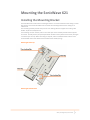
Mounting the SonicWave 621
Installing the Mounting Bracket
The SonicWave 621 comes with a mounting bracket so it can be mounted on the ceiling or other
flat surface. This section describes how to attach the mounting bracket to the ceiling or an
indoor wall.
The mounting bracket provides two pairs of T‐bar locking tabs that support two ceiling T‐bar
widths: 15/16 inch and 9/16 inch.
For mounting on a flat surface, holes in the T‐bar clips on the bracket provide insertion points
for screws. Use #6 (3.5mm) zinc plated pan head machine screws (sheet metal screws) of length
1.25 inches (31.75 mm). When mounting on drywall, anchors should be used. Anchors must
accommodate the screws and be rated to hold at least 10 lbs (4.5 kg).
Mounting Bracket Top
Mounting Bracket Bottom

SonicWall
3
Safety and Regulatory Information
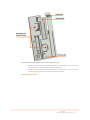
To attach the mounting bracket to the ceiling using T-bar clips:
1 Press the top side of the mounting bracket against the ceiling tile T‐bar so that the T‐
bar locking tabs on the mounting bracket are depressed.
2 Rotate the mounting bracket until the ceiling T‐bar slides into the T‐bar clips on the
mounting bracket and the T‐bar locking tabs click into place.
T-Bar with Mounting Plate

4
Safety and Regulatory Information
To attach the mounting bracket to the ceiling or to a wall using screws:
1 Place the top side of the mounting bracket against the ceiling or wall and mark the
locations for the two screw insertion points.
2 Drill starter holes at the marked locations. For a wood wall, use a drill bit that fits
the screws. For drywall, use a drill bit that fits the anchors.
3 For drywall, screw in the anchors.
4 Place the mounting bracket against the wall with the holes lined up on the marks or
anchors.
5 Using the screws and a screwdriver, securely attach the mounting bracket to the
ceiling or wall.
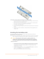
Installing the SonicWave 621
This section describes how to connect the PoE and network cables and then attach the
SonicWave 621 to the mounting bracket.
The SonicWave 621 is powered by a power adapter (sold separately) or by Power over Ethernet
(PoE). SonicWall recommends using CAT 5e cables to connect PoE to the access point.
CAUTION: When using PoE to power the device, an 802.3at compliant PoE
injector, PoE enabled switch, or SonicWall PoE enabled appliance is required to
provide power to each SonicWave 621. To maintain power to the SonicWave 621,
the maximum length of CAT 5e cable from the PoE device to the SonicWave 621 is
100 meters (333 feet).
1 Using an Ethernet cable, connect the Data in port on the PoE Injector or switch to
an interface on your network device. If using a SonicWall firewall, connect it to an
existing WLAN zone interface on the firewall or to an unused interface to be
configured later in SonicOS.
2 Using a second Ethernet cable, connect the Data and Power Out port on the PoE
injector to the LAN/POE port on your SonicWave 621.
Refer to your PoE Installation Guide for more information.

SonicWall
5
Safety and Regulatory Information
3 Plug the power cord of the PoE Injector into an appropriate power outlet.
4 Wait up to two minutes for the LAN LED on the SonicWave 621 to illuminate. This
indicates an active connection.
To attach the SonicWave 621 to the mounting bracket:
1 Line up the two mounting tab insert points on the back of the SonicWave 621 with
the mounting tabs on the mounting bracket.
2 Insert the mounting tabs into the SonicWave 621 and slide the access point down
until the locking tab
on the bracket clicks into place on the SonicWave.
Safety Information for Installation
and Operation
• Installation Requirements
• RF Safety Distance
• Cable Connections
• Power Supply Information
• Restricted Environments
• Radio Approvals
• Radio or Television Interference
• Wireless Interoperability
Products with “UL 2043” printed on their product labels are within the limit specified in the “UL
2043 Standard for Fire Test for Heat and Visible Smoke Release for Discrete Products Installed in
Air‐Handling Spaces” (Plenum). Applies only when powered through PoE. The PoE power supply
is not covered the by the UL 2043 evaluation of this Access Point.
NOTE: Additional regulatory notifications and information for this product can be
found online at:
https://www.sonicwall.com/support/technical‐documentation
SonicWave 621 complies with FCC U‐NII New Rules.
Regulatory Model/Type Product Name
APL68-108 SonicWave 621

6
Safety and Regulatory Information
Installation Requirements
WARNING: The following conditions are required for proper
installation:
1 Mount in a location away from direct sunlight and sources of heat. A maximum ambient
temperature of 104º F (40º C) is recommended.
2 Route cables away from power lines, fluorescent lighting fixtures, and sources of noise
such as radios, transmitters, and broadband amplifiers.
3 Ensure that no water or excessive moisture can enter the unit.
4 Allow unrestricted airflow around the unit. A minimum of 1 inch (25.44mm) clearance is
recommended.
5 Consideration must be given to the connection of the equipment to the supply circuit.
Appropriate consideration of equipment nameplate ratings must be used when
addressing this concern. Do not overload the circuit.
6 This equipment is not intended for use at workplaces with visual display units, in
accordance with §2 of the German ordinance for workplaces with visual display units. To
avoid incommoding reflections at visual display workplaces, this device must not be
placed in the direct field of view.
RF Safety Distance
The antennas used for this transmitter must be installed to provide a separation distance of at
least 20 cm from all persons and must not be co‐located or operating in conjunction with
another antenna or transmitter.
Cable Connections
All Ethernet and RS232 (Console) cables are designed for intra‐building connection to other
equipment. Do not connect these ports directly to communication wiring or other wiring that
exits the building where the appliance is located.

SonicWall
7
Safety and Regulatory Information
Power Supply Information
When this product's power is provided by the Ethernet cable plugged in to the “LAN/POE” port,
this is called “Power over Ethernet” or “PoE”. The PoE source should only be UL listed marked
“Class 2” or “LPS” with an output rated 48 VDC, minimum 0.3 A, Tma: minimum 40 degrees C.
When powering via external power adapter via barrel jack, use only UL listed power supply
marked “Class 2” or “LPS” with output rated 12Vdc, min. 3.0A, Tma: minimum 40 degrees C.
(External power adapter is not provided with this product but can be purchased from SonicWall.
Reliable grounding of external power adapter purchased from SonicWall must be maintained.
Particular attention must be given to power supply connections other than direct connections to
the branch circuits, such as power strips.)
Restricted Environments
The SonicWall wireless device, like other radio devices, emits radio frequency electromagnetic
energy. The SonicWall wireless device operates within the guidelines found in radio frequency
safety and recommendations. These standards and recommendations reflect the consensus of
the scientific community and result from deliberations of panels and committees of scientists
who continually review and interpret the extensive research literature. In some situations or
environments, the use of the SonicWall wireless device may be restricted by the proprietor of
the building or responsible representatives of the applicable organization.
Examples of such situations include the following:
• Using the SonicWall wireless device equipment on board airplanes, or
• Using the SonicWall wireless device equipment in any other environment where the risk of
interference with other devices or services is perceived or identified as being harmful.
If you are uncertain of the policy that applies to the use of wireless devices in a specific
organization or environment (an airport, for example), you are encouraged to ask for
authorization to use the SonicWall wireless device before you turn it on.
WARNING: Explosive Device Proximity Warning: Do not operate a
portable transmitter (such as a wireless network device) near
unshielded blasting caps or in an explosive environment unless the
device has been modified to be qualified for such use.
WARNING: Use on Aircraft Caution: Regulations of the FCC and FAA
prohibit airborne operation of radio-frequency wireless devices because
their signals could interfere with critical aircraft instruments.

8
Safety and Regulatory Information
Radio Approvals
It is important to ensure that you only use your radio device in countries where the device is
approved for use. To determine whether you are allowed to use your wireless network device in
a specific country, check to see if the radio type number that is printed on the identification label
of your device or listed on the radio approval list posted on the general SonicWall support site at:
https://www.sonicwall.com/support.
Radio or Television Interference
The SonicWall SonicWave 621 wireless network device must be installed and used in strict
accordance with the manufacturer’s instructions as described in the user documentation that
comes with the product. SonicWall Inc.
is not responsible for any radio or television interference caused by unauthorized modification of
the devices included with this SonicWall Wireless device kit, or the substitution or attachment of
connecting cables and equipment other than that specified by SonicWall Inc. The correction of
interference caused by such unauthorized modification, substitution or attachment is the
responsibility of the user. SonicWall Inc. and its authorized resellers or distributors are not liable
for any damage or violation of government regulations that may arise from the user failing to
comply with these guidelines.
Wireless Interoperability
The SonicWall Wireless WLAN products are designed to be interoperable with any wireless LAN
product that is based on direct sequence spread spectrum (DSSS) radio technology and
orthogonal frequency division multiplexing (OFDM) and to comply with the following standards:
• IEEE 802.11a\ac Standard on 5 GHz Wireless LAN
• IEEE 802.11b‐1999 Standard on 2.4 GHz Wireless LAN
• IEEE 802.11g Standard on 2.4 GHz Wireless LAN
• IEEE 802.11n Standard on 2.4 GHz and 5 GHz Wireless LAN
• Wireless Fidelity (Wi‐Fi) certification, as defined by the WECA (Wireless Ethernet
Compatibility Alliance)
Consignes de sécurité pour
l'installation et l'utilisation
• Exigences relatives à l'installation

SonicWall
9
Safety and Regulatory Information
• Raccordements
• Informations sur l’alimentation électrique
Exigences relatives à l'installation
AVERTISSEMENT: Les conditions suivantes sont requises pour une
installation correcte:
1 Procédez au montage dans un endroit à l'abri des rayons du soleil et des sources de
chaleur. Une température ambiante maximale de 40 °C (104 °F) est recommandée.
2 Faites passer les câbles à une distance raisonnable des lignes électriques, des
luminaires à lampe fluorescente et des sources de bruit telles que les radios, les
émetteurs et les amplificateurs à large bande.
3 Veillez à éviter tout contact de l'appareil avec de l'eau ou une humidité excessive.
4 Veillez à ce que l'air puisse facilement circuler autour de l'unité et à travers les
aérations prévues sur le côté de l'unité. Laissez un espace d'au moins 25,44 mm.
5 Portez une attention particulière au raccordement de l'équipement au circuit
d'alimentation, de manière à ce qu'une éventuelle surcharge des circuits ait un impact
minime sur la protection contre les surintensités et sur les câbles d'alimentation.
Respectez pour cela les mentions figurant sur la plaque d'identification du produit.
Raccordements
Tous les câbles Ethernet et RS232 (console) sont conçus pour la connexion à d'autres appareils à
l'intérieur d'un même bâtiment. Ne reliez pas ces ports directement à des câbles de
communication ou à d'autres câbles qui sortent du bâtiment dans lequel se trouve l'appareil
SonicWall.
Informations sur l’alimentation
électrique
Lorsque ce produit est alimenté par le câble Ethernet connecté au port “LAN1/POE”; ce type
d’alimentation est appelé “Power over Ethernet” ou “PoE”. La source d’alimentation par câble

10
Safety and Regulatory Information
Ethernet (PoE) utilisée doit impérativement être homologuée UL, porter la mention “Classe 2” ou
“LPS”, et avoir une puissance de sortie nominale de 48 V CC, 0,3 A minimum, TA : 40 °C.
Lors de l’alimentation via un adaptateur d’alimentation externe via une prise à barillet, utilisez
uniquement une alimentation homologuée UL portant la mention “Classe 2” ou “LPS” avec une
sortie nominale de 12Vcc, min. 3,0A, Tma: minimum 40 degrés C TA : 40 °C.
Sicherheitshinweise für den Einbau
und Betrieb
• Weitere hinweise zur montage
• Kabelverbindungen
• Informationen zur stromversorgung
Weitere hinweise zur montage
WARNUNG: Zu Ihrer eigenen Sicherheit beachten Sie alle in diesem Abschnitt
aufgeführten Anweisungen.
1 Wählen Sie für die Montage einen Ort, der keinem direkten Sonnenlicht ausgesetzt ist
und sich nicht in der Nähe von Wärmequellen befindet. Die Umgebungstemperatur darf
nicht mehr als 40 °C betragen.
2 Führen Sie die Kabel nicht entlang von Stromleitungen, Leuchtstoffröhren und
Störquellen wie Funksendern oder Breitbandverstärkern.
3 Stellen Sie sicher, dass das Gerät vor Wasser und hoher Luftfeuchtigkeit geschützt ist.
4 Stellen Sie sicher, dass die Luft um das Gerät herum zirkulieren kann und die
Lüftungsschlitze an der Seite des Gehäuses frei sind. Hier ist ein Belüftungs‐abstand von
mindestens 26 mm einzuhalten.
5 Prüfen Sie den Anschluss des Geräts an die Stromversorgung, damit der
Überstromschutz sowie die elektrische Leitung nicht von einer eventuellen Überlastung
der Stromversorgung beeinflusst werden. Prüfen Sie dabei sorgfältig die Angaben auf
dem Aufkleber des Geräts. Überlasten Sie nicht den Stromkreis.
6 Dieses Gerät ist nicht zur Verwendung an Arbeitsplätzen mit visuellen Anzeigegeräten
gemäß § 2 der deutschen Verordnung für Arbeitsplätze mit visuellen Anzeigegeräten

SonicWall
11
Safety and Regulatory Information
vorgesehen. Um störende Reflexionen am Bildshirmarbeitsplatz zu vermeiden, darf
dieses Produkt nicht im unmittelbaren Gesichtsfeld platziert verden.
Kabelverbindungen
Alle Ethernet- und RS232-C-Kabel eignen sich für die Verbindung von Geräten in Innenräumen.
Schließen Sie an die Anschlüsse der SonicWallkeine Kabel an, die aus dem Gebäude
herausgeführt werden, in dem sich das Gerät befindet.
Informationen zur stromversorgung
Die Stromversorgung durch das Ethernet‐Kabel in die “LAN/POE”‐Anschluss angeschlossen
vorgesehen ist, wird dies als “Power over Ethernet” oder “PoE.” Dieses Produkt darf nur in
Verbindung mit einem für den Europäischen Markt genehmigten und mit dem Logo
„LPS.“ Ausgang: 48 VDC Gleichsspannung, mind. 0,3 A, mindest TMA mindestens 40° Grad C,
betrieben werden.
Wenn dieses Produkt sollte nur mit einem für den Europäischen Markt genehmigten Netzteil mit
dem Logo “I.T.E. LPS” und einer Ausgangsleistung von12 VDC, mind. 3,0 A, Tma: mind. 40 Grad C,
betrieben werden.

12
Safety and Regulatory Information
安裝 SonicWave 621
裝設安裝支架
SonicWave 621 隨附安裝支架,可安裝在天花板或其他平坦表面上。本節內容將說明如何
將安裝支架固定於天花板或室內牆面上。
安裝支架提供兩組 T 型鎖定耳片,以支撐兩種天花板 T 型支架的寬度:15/16 英吋和
9/16 英吋。
若是安裝在平面上,支架的 T 型支架固定夾上有提供螺絲插入點的孔。使用 6 號 (3.5
公釐) 鍍鋅長平頭機用螺絲 (金屬板螺絲),長度 1.25 英吋 (31.75 公釐)。若是架設在
乾牆面,請使用壁虎套。壁虎套應配合螺絲大小,且額定可承重至少 10 磅 (4.5 公斤)。
安裝支架頂端

SonicWall
13
Safety and Regulatory Information
安裝支架底部
如何使用 T 型支架固定夾將安裝支架固定至天花板:
1 將安裝支架的頂端壓向天花板的 T 型支架,藉此按下安裝支架的 T 型鎖定耳片。
2 旋轉安裝支架,直到天花板 T 型支架滑入安裝支架的 T 型支架固定夾中,且 T 型鎖
定耳片卡入至正確位置為止。

14
Safety and Regulatory Information
如何使用螺絲將安裝支架固定到天花板或牆面:
1 將安裝支架的頂端靠在天花板或牆面上,並標記兩個螺絲插入孔的位置。
2 在標記的位置鑽出起始孔。若是架設在木頭牆面,請使用符合螺絲大小的鑽子。若是
架設在乾牆面,請使用符合提供的壁虎套大小的鑽子。
3 若是架設在乾牆面,請將螺絲鎖入壁虎套。
4 將安裝支架靠在牆面上,並將鑽孔對齊標記或壁虎套。
5 使用螺絲和螺絲起子,將安裝支架穩固地安裝在天花板或牆面上。
安裝 SonicWave 621
本節說明連接 PoE 和網路線的方式,以及將 SonicWave 621 固定至安裝支架的方式。
SonicWave 621 採用變壓器 (另售) 或乙太網路供電 (PoE) 技術來供電。 SonicWall 建
議使用 CAT 5e 纜線將
PoE 連接至存取點。
注意:在使用 PoE 為裝置供電時,須使用符合 802.3at 標
準的 PoE 轉換器、具備 PoE 功能的交換器,或 SonicWall 具備 PoE 功能的設
備,對每一台
SonicWave 621 提供電力。
為了維持 SonicWave 621 所需的電力,連接 PoE 裝置與 SonicWave 621 的 CAT
5e 纜線長度最長不可超過 100 公尺 (333 英呎)。
如要將 SonicWave 621 連接至 PoE 和網路:
1 使用乙太網路線,將 PoE 轉換器或交換器上的資料輸入連接埠連接到您網路裝置上的
介面。如果使用

SonicWall
15
Safety and Regulatory Information
SonicWall 防火牆,則請連接到防火牆上現有的 WLAN 區介面,或是連接到未使用的
介面,方便稍後於
SonicOS 中進行設定。
2 使用另一條乙太網路線將 PoE 轉換器上的資料和電源輸出連接埠連接到 SonicWave
621 上的 LAN/POE 連接埠。
請參閱 PoE 安裝指南以瞭解更多資訊。
3 將符合 PoE 轉換器電源線插入適當的電源插座。
4 等候兩分鐘,SonicWave 621 的 LAN LED 隨即亮起。這表示連線開始作用。
如要將 SonicWave 621 固定至安裝支架:
1 將 SonicWave 621 背面的兩個安裝耳片插入點對齊到安裝支架上的安裝耳片。
2 將安裝耳片插入 SonicWave 621 並向下滑動存取點,直到支架上的鎖定耳片卡進
SonicWave。
安全須知與規範資訊
產品標籤上印有「UL 2043」的產品符合「UL 2043 Standard for Fire Test for Heat
and Visible Smoke Release for
Discrete Products Installed in Air-Handling Spaces」(Plenum) 中所規範的限制。僅
適用於透過 PoE 供電的情況。PoE 電源供應器並未涵蓋在 UL 2043 對此存取點的評估範
圍內。
規格型號
1 避免架設於陽光直射處和熱源所在位置。建議的最高環境溫度為 104º F (40º C)。
2 接線路徑請避開電線、日光燈具及雜訊來源,像是無線電、發射器和寬頻強波器
3 確認不會有水或大量濕氣進入裝置。
4 裝置周圍的通風與流過裝置旁風扇的氣流不應受阻。建議的至少應相隔 1 吋 (25.44
公釐)。
5 務必考量設備與供電電路之間的連接。因應上述考量時,務必採用設備名牌上的額定
值。
勿讓電路過載。
型号
型号
APL68-108
SonicWave 621
警告
:
正確安裝需要符合以下條件。

16
Safety and Regulatory Information
6 根據德國對於具視覺顯示裝置的工作場所法令 ?2,此設備並非用於具視覺顯示裝置的
工作場所。為避免干擾視覺顯示工作場所的反射效果,本裝置不得放置於直視範圍內。
纜線連接
所有乙太網路與 RS232 (主控台) 線路,均為與建築物內其他設備連接所設計。請勿將這
些連接埠直接連接到通訊接線,或連接到 SonicWall 設備所在建築物之外的其他接線上。
電源供應器資訊
本產品是經由乙太網路線插入「LAN/POE」連接埠的方式供電,這被稱為「乙太網路供
電」或「PoE」。
POE 來源僅限 UL 所列標有「第 2 級」或「LPS」的設備,其額定輸出電壓為 48 VDC,最小
0.3 A,Tma:最低攝氏 40 度。
若透過外部電源配接器連接插座供電,使用的供電來源應僅限 UL 所列標有「第 2 級」或
「LPS」的設備,其額定輸出電壓為 12Vdc,最小 3.0A,Tma:最低攝氏 40 度。

SonicWall
17
Safety and Regulatory Information
(台灣 RoHS)/限用物質含有情況標示資
訊
單元 Unit
限用物質及其化學符號
Restricted substances and its chemical symbols
鉛
Lead
(Pb)
汞
Mercury
(Hg)
鎘Cadmium
(Cd)
六價鉻
Hexavalent
chromium
(Cr+6)
多溴聯苯
Polybrominated
biphenyls
(PBB)
多溴二苯醚
Polybrominated
diphenyl ethers
(PBDE)
機箱/檔板 (Chassis/Bracket)
-
○
○
○
○
○
機械部件 (風扇、散熱器等)
(Mechnical parts (fan,
heatsink, etc.))
-
○
○
○
○
○
電路板組件 (PCBA)
-
○
○
○
○
○
電線/連接器 (Cable/Connector)
-
○
○
○
○
○
電源設備 (Power supply)
-
○
○
○
○
○
配件 (Accessories)
-
○
○
○
○
○
備註 1.〝○〞係指該項限用物質之百分比含量未超出百分比含量基準值。
備註 2.〝-〞係指該項限用物質為排除項目。
附註:有關本產品的其他法規須知與資訊可於
下方網站線上取得:
https://www.sonicwall.com/support 保固資
訊:
所有 SonicWall 裝置均附帶 1 年有限硬體保固,為保修期內的缺陷零件提供關鍵的置
換零件。如需產品保固的詳細資訊,請瀏覽保固資訊頁面:
https://www.sonicwall.com/support。

18
Safety and Regulatory Information
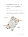
SonicWave 621 のインストール
取り付けブラケットの設置手順
SonicWave 621 は、付属の取り付けブラケットを使用して天井や他の平面に取り付けることが
できます。ここでは
、取り付けブラケットを天井や室内の壁に取り付ける手順を説明します。
取り付けブラケットには、2 対の T バー固定タブがあり、15/16 インチと 9/16 インチの 2 種類
の天井 T バー幅に対応しています。
平面上に設置する場合は、ブラケットの T バー クリップの穴がねじの差し込み位置になります。
6 番 (3.5mm 径)、長さ 1.25 インチ (31.75 mm) の亜鉛メッキなべ小ねじ (薄板用タッピンねじ) を
使用してください。乾式壁に取り付ける場合はアンカーが必要です。使用するネジに適合する
耐荷重 10 lbs (4.5 kg) 以上のアンカーを使用してください。
取り付け用ブラケットの表側

SonicWall
19
Safety and Regulatory Information
取り付け用ブラケットの裏側
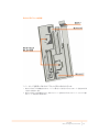
T バー クリップを使用して取り付けブラケットを天井に取り付けるには:
1 取り付けブラケットの表側を天井タイル T バーに押し付け、取り付けブラケットの T バー固定タブが押
し込まれる状態にします。
2 取り付けブラケットを回転させながら、天井タイル T バーを取り付けブラケットの T バー クリップに差し
込み、T バー固定タブで固定します。

20
Safety and Regulatory Information
ねじを使用して取り付けブラケットを天井または壁に取り付けるには:
1 取り付けブラケットの表側を天井または壁に当て、2 つのねじ位置に印を付けます。
2 印を付けた位置にドリルで下穴を開けます。木材の壁に取り付ける場合は、ねじのサイズ
に適合するドリルビットを使用してください。乾式壁に取り付ける場合は、アンカーのサイズ
に適合するドリルビットを使用してください。
3 乾式壁に取り付ける場合は、アンカーを挿入します。
4 取り付けブラケットを壁に当て、穴の位置を印またはアンカーに合わせます。
5 ドライバーでねじを締め込んで、取り付けブラケットを天井または壁に固定します。
SonicWave 621 のインストール
ここでは、PoE とネットワーク ケーブルを接続し、SonicWave 621 を取り付けブラケットに取り付
ける手順を説明します。
SonicWave 621 への電力供給には電源アダプタ (別売) または Power over Ethernet (PoE) を
使用します。
SonicWall では、CAT 5e のケーブルを使用して PoE をアクセス ポイントに接続することを推奨
します。
注意: PoE を使用して電力を供給する場合は、各 SonicWave 621 に電力を供給する
802.3at 準拠の
PoE インジェクター、PoE 対応スイッチ、または SonicWall PoE 対応装置が必要です。
SonicWave 621 への電力供給を維持するために、PoE 機器から SonicWave 621 まで
の CAT 5e ケーブルの長さを 100 メートル (333 フィート) 以内にしてください。
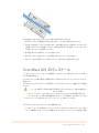
SonicWave 621 を PoE とネットワークに接続するには:
1 イーサネット ケーブルを使用して、PoE インジェクターまたはスイッチの Data In ポートをネ
ットワーク機器のインターフェースに接続します。SonicWall ファイアウォールを使用する場
La page charge ...
La page charge ...
La page charge ...
La page charge ...
La page charge ...
La page charge ...
La page charge ...
La page charge ...
La page charge ...
La page charge ...
La page charge ...
La page charge ...
-
 1
1
-
 2
2
-
 3
3
-
 4
4
-
 5
5
-
 6
6
-
 7
7
-
 8
8
-
 9
9
-
 10
10
-
 11
11
-
 12
12
-
 13
13
-
 14
14
-
 15
15
-
 16
16
-
 17
17
-
 18
18
-
 19
19
-
 20
20
-
 21
21
-
 22
22
-
 23
23
-
 24
24
-
 25
25
-
 26
26
-
 27
27
-
 28
28
-
 29
29
-
 30
30
-
 31
31
-
 32
32


dans d''autres langues
Documents connexes
-
SonicWALL SonicWave 641 Mode d'emploi
-
-
SonicWALL SWS14-48FPOE Guide de démarrage rapide
-
-
-
SonicWALL TZ270 Mode d'emploi
-
SonicWALL POE60U-1BT-5 Guide d'installation
-
-