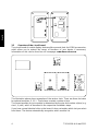
Vous trouverez ci-dessous de brèves informations pour Module analogique KUM TYKUM-08-A. Ce module permet d'ajouter des sorties analogiques à votre appareil KERN. Il est livré avec un noyau de ferrite et est conçu pour être installé à l'intérieur du terminal de l'appareil. Il dispose de connexions pour l'alimentation, la sortie 0-10 VDC et la sortie 4-20 mA. Il faut prendre des précautions de sécurité, notamment en ce qui concerne l'électricité statique et la tension d'alimentation. Le module nécessite un câble d'interface d'un diamètre minimum de 6 mm. Assurez-vous que le capuchon se referme correctement sur le câble pour éviter toute pénétration de liquide.
Vous trouverez ci-dessous de brèves informations pour Module analogique KUM TYKUM-08-A. Ce module permet d'ajouter des sorties analogiques à votre appareil KERN. Il est livré avec un noyau de ferrite et est conçu pour être installé à l'intérieur du terminal de l'appareil. Il dispose de connexions pour l'alimentation, la sortie 0-10 VDC et la sortie 4-20 mA. Il faut prendre des précautions de sécurité, notamment en ce qui concerne l'électricité statique et la tension d'alimentation. Le module nécessite un câble d'interface d'un diamètre minimum de 6 mm. Assurez-vous que le capuchon se referme correctement sur le câble pour éviter toute pénétration de liquide.


-
 1
1
-
 2
2
-
 3
3
-
 4
4
-
 5
5
-
 6
6
-
 7
7
-
 8
8
-
 9
9
-
 10
10
-
 11
11
-
 12
12
-
 13
13
-
 14
14
-
 15
15
-
 16
16
-
 17
17
-
 18
18
-
 19
19
-
 20
20
-
 21
21
-
 22
22
-
 23
23
-
 24
24
-
 25
25
-
 26
26
-
 27
27
-
 28
28
-
 29
29
-
 30
30
-
 31
31
-
 32
32


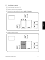
Vous trouverez ci-dessous de brèves informations pour Module analogique KUM TYKUM-08-A. Ce module permet d'ajouter des sorties analogiques à votre appareil KERN. Il est livré avec un noyau de ferrite et est conçu pour être installé à l'intérieur du terminal de l'appareil. Il dispose de connexions pour l'alimentation, la sortie 0-10 VDC et la sortie 4-20 mA. Il faut prendre des précautions de sécurité, notamment en ce qui concerne l'électricité statique et la tension d'alimentation. Le module nécessite un câble d'interface d'un diamètre minimum de 6 mm. Assurez-vous que le capuchon se referme correctement sur le câble pour éviter toute pénétration de liquide.
dans d''autres langues
- English: KERN TYKUM-08-A Installation guide
- Deutsch: KERN TYKUM-08-A Installationsanleitung
Documents connexes
-
KERN TYKUM-08-A Guide d'installation
-
-
-
-
-
-
-
-
-
KERN TFKB 65K-4-B Mode d'emploi