
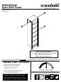
9900706COM
Open Shelf Tower
B349900706COM0
THIS INSTRUCTION BOOKLET CONTAINS IMPORTANT SAFETY INFORMATION. PLEASE READ AND KEEP FOR FUTURE REFERENCE.
For the latest information on SystemBuild products
follow us at Ameriwood Home
Tube
You
Date of Purchase ___ / ___ / ___
Lot Number:
Do Not Return This Product!
Contact our customer service team for help first.
Call: 1-866-452-4081 (toll free)
Visit: www.systembuild.com
Assembly Difficulty Meter
Easy Tough
Secure Your Furniture
Keep your home and family safe
with the wall anchor kit that is
included with the product.
Serious or fatal crushing injuries can
occur from tipping furniture.
WARNING: Manufacturer assumes no liability
for improper installation or excessive loads
placed on screws or bracket. This wall anchor
is not a substitute for proper adult supervision.

Contact Us!
Helpful Hints
2
systembuild.com
Do NOT return this product!
Contact our friendly customer service team first for help.
Visit systembuild.com to view the
limited warranty valid in the U.S. and Canada.
Assembly Tips
- Open your item in the area you plan to keep it to avoid excessive heavy lifting.
- Identify, sort and count the parts before attempting assembly.
- Compression dowels are lightly tapped in with a hammer.
- Make sure to always face the point on the top of the Cam Lock towards the
outer edge.
- Use all the nails provided for the back panel and spread them out equally.
- Back panel must be used to make sure your unit is sturdy.
- Do NOT use harsh chemicals or abrasive cleaners on this item.
- Never push, pull, or drag your furniture.
Tube
You
Tub e
You
PEOPLE NEEDED FOR ASSEMBLY: 1-2
Call us!
1-866-452-4081
Monday-Friday

3
systembuild.com
Before You Start
Quick
Tip
Assembly
Cam Lock Fastening System
This Cam Lock Fastening System will be used throughout the assembly process.
Tub e
You
Read through each step carefully and follow the proper order
Separate and count all your parts and hardware
Parts are labeled on the surface or edge of the part
Give yourself enough room for the assembly process
Have the following tools: #2 Phillips Head Screwdriver and
Hammer
Caution: If using a power drill or power screwdriver for screwing,
please be aware to slow down and stop when screw is tight.
Failure to do so may result in stripping the screw.
Press parts together so CAM BOLT inserts
into edge hole.
Using a screwdriver, turn the CAM LOCK clockwise to
lock the CAM LOCK and CAM BOLT into their holes and
fastening parts together.
Press CAM BOLT into hole. Press CAM LOCK into hole.
Arrow to point towards end
hole in edge of part.
End hole
1
3
2
4

4
systembuild.com
Quick
Assembly
Tip
Before You Start
Please Note:
You may need to lightly tap the wood dowels into the holes during
your assembly process.

5
systembuild.com
Board Identification
Not actual size
Tube
You
Left Panel
39900706010
Right Panel
39900706020
Shelf (x2)
39900706040
Back Panel
K157170600
This piece is paperboard construction.
It is not made from wood, but is
required for the assembly of your unit.
F
Top
39900706030
B
A
D
C
G
BACK
PNL
Left Molding
39900706060
Right Molding
39900706070
Shelf Rail (x2)
39900706080
Lower Rail
39900706100
Support Rail (x2)
39900000110
H
JK
E
Adjustable Shelf (x4)
39900706050
Adjustable Shelf Rail (x4)
39900706090
I

6
systembuild.com
Board Identification
Not actual size
Tube
You
A
B
D
C
This piece is paperboard construction.
It is not made from wood, but is
required for the assembly of your unit.
BACK
PNL
F
E
G
D
K
K
E
E
E
H
H
I
I
I
I
J

7
systembuild.com
Part List
Tube
You
(x16)
#A22700
cam lock
(x16)
#A22710
cam bolt
(x4)
#A23030
confirmat
4
Actual Size
(x8)
#A21670
wood dowel
(x8)
#A54710
wedge
3
12
(x6)
#A22770
quickloc
(x22)
#A22790
locking pin
(x22)
#A22795
locking sleeve
(x4)
#A21110
nail
(x3)
#A53820
bracket
(x3)
#A11080
7/16" screw
5
6789
10
11 (x4)
#A13950
3-1/2" screw
12
(x16)
#A80250
shelf support
(x8)
#A80480
shelf support
(x6)
#A20940
wall anchor
(x6)
#A12700
7/8" pan head
(x6)
#A13020
1-3/4" pan head
13 14
15
16
17

8
systembuild.com
Part List
Not actual size
Tube
You
18
(x3)
#I20750
clothes rod
19
(x1)
#A23220
torx hex key
Hammer Block
(piece of wood to use
to attach legs)

9
systembuild.com
STEP1
Tub e
You
(x8)
2
2
7
(x5)
7
2
2
2
2
2
2
2
7
7
7
7
A

10
systembuild.com
STEP2
Tub e
You
2
7
(x8) (x5)
7
2
7
7
7
7
B2
2
22
2
2
2

11
systembuild.com
STEP3
Tub e
You
F
G
6
6
(x10)
6
6
6
6
6
6
6
6
6
19
(x1)

12
systembuild.com
STEP4
Tube
You
Position and insert the locking pins (6) of the Left Molding (F) into the edge holes of the Left Panel (A) as
shown.
Be sure both parts are positioned as shown. Place the hammer block on top of molding in each of the 5
locking bolt locations and give a firm strike to lock together. The locking pin (6) will snap into the
locking sleeve (7).
IMPORTANT NOTICE: Once locked together, parts cannot be separated.
Note: A rubber mallet can be used in place of a hammer and hammer block.
F
A
Hammer Block

13
systembuild.com
STEP5
Tub e
You
Position and insert the locking pins (6) of the Right Molding (G) into the edge holes of the Right Panel (B)
as shown.
Be sure both parts are positioned as shown. Place the hammer block on top of molding in each of the 5
locking bolt locations and give a firm strike to lock together. The locking pin (6) will snap into the
locking sleeve (7).
IMPORTANT NOTICE: Once locked together, parts cannot be separated.
Note: A rubber mallet can be used in place of a hammer and hammer block.
G
B
Hammer Block

14
systembuild.com
STEP6
Tub e
You
Proper orientation of CAM LOCK
Tip
Assembly
Quick
135
(x8)
x2
(x8) (x4)
1
3
5
3
1
5
3
3
1
1
D

15
systembuild.com
STEP7
Tub e
You
H
D
5
Turn screw clockwise
to lock parts together.
x2

16
systembuild.com
STEP8
Tub e
You
15
(x8) (x2)
Proper orientation of CAM LOCK
Tip
Assembly
Quick
1
1
5
K
J
x2
1
1
5

17
systembuild.com
STEP9
Tub e
You
UNLOCKLOCK
K
K
D
D
A
J
F

18
systembuild.com
STEP10
Tube
You
UNLOCKLOCK
B
D
D
K
K
H
G

19
systembuild.com
STEP11
(x4)
Tube
You
4
4
4
4
4
C
A
B
finished edge

20
systembuild.com
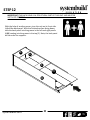
STEP12
Tube
You
BACK
PNL
With the help of another person, turn the unit on its front side.
Unfold the back panel. With the finished surface facing down,
slide the back panel into the groove in the left and right panels
(A&B) seating into the groove in the top (C). Note, the back panel
will be under the supports.
IMPORTANT! THE BACK PANEL IS A STRUCTURAL PART OF THIS UNIT AND MUST BE
INSTALLED PROPERLY.
B
A
K
K
La page est en cours de chargement...
La page est en cours de chargement...
La page est en cours de chargement...
La page est en cours de chargement...
La page est en cours de chargement...
La page est en cours de chargement...
La page est en cours de chargement...
La page est en cours de chargement...
La page est en cours de chargement...
La page est en cours de chargement...
La page est en cours de chargement...
La page est en cours de chargement...
La page est en cours de chargement...
La page est en cours de chargement...
La page est en cours de chargement...
La page est en cours de chargement...
La page est en cours de chargement...
La page est en cours de chargement...
-
 1
1
-
 2
2
-
 3
3
-
 4
4
-
 5
5
-
 6
6
-
 7
7
-
 8
8
-
 9
9
-
 10
10
-
 11
11
-
 12
12
-
 13
13
-
 14
14
-
 15
15
-
 16
16
-
 17
17
-
 18
18
-
 19
19
-
 20
20
-
 21
21
-
 22
22
-
 23
23
-
 24
24
-
 25
25
-
 26
26
-
 27
27
-
 28
28
-
 29
29
-
 30
30
-
 31
31
-
 32
32
-
 33
33
-
 34
34
-
 35
35
-
 36
36
-
 37
37
-
 38
38


dans d''autres langues
- English: Dorel Home 9900706COM
- español: Dorel Home 9900706COM
Documents connexes

Autres documents
-
Ameriwood Home HD45101 Mode d'emploi
-
-
-
-
-
-
-
Ameriwood HD83945 Mode d'emploi
-