Fortin EVO-ONE Volkswagen Golf 2016 Guide d'installation
- Taper
- Guide d'installation

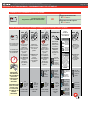
* HOOD PIN HOOD STATUS : THE HOOD PIN SWITCH MUST BE INSTALLED
IF THE VEHICLE CAN BE REMOTE STARTED WITH THE HOOD OPEN,
SET FUNCTION A11 TO OFF.
CONTACT
DE CAPOT
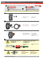
MANDATORY INSTALL | INSTALLATION OBLIGATOIRE Notice: the installation of safety
elements are mandatory. The hood pin
is an essential security element and
must be installed.
Notice: l'installation des éléments de
sécurité est obligatoire. Le contact de
capot est un élément de sécurité
essentiel et doit absolument être
installé.
THIS MODULE MUST BE INSTALLED BY A
QUALIFIED TECHNICIAN. A WRONG
CONNECTION CAN CAUSE PERMANENT
DAMAGE TO THE VEHICLE.
CE MODULE DOIT ÊTRE INSTALLÉ PAR
UN TECHNICIEN QUALIFIÉ, TOUTE
ERREUR DANS LES BRANCHEMENTS
PEUT OCCASIONNER DES DOMMAGES
PERMANENTS AU VÉHICULE.
STATUT DE CAPOT : LE CONTACT DE CAPOT, DOIT ÊTRE INSTALLÉ SI LE
VÉHICULE PEUT DÉMARRER À DISTANCE, LORSQUE LE CAPOT EST OUVERT,
PROGRAMMEZ LA FONCTION A11 À NON.
A11 OFF
NON
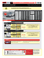
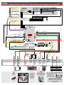
ADDENDUM - SUGGESTED WIRING CONFIGURATION
ADDENDA - SCHÉMA DE BRANCHEMENT SUGGÉRÉ
ALL REV.: 20211111
ONLY COMPATIBLE WITH AUTOMATIC TRANSMISSION VEHICLES.
COMPATIBLE AVEC VÉHICULE À TRANSMISSION AUTOMATIQUE SEULEMENT.
Guide # 82411
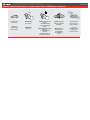
Vehicle functions supported in this diagram (functional if equipped) | Fonctions du véhicule supportées dans ce dia-
gramme (fonctionnelles si équipé)
Immobilizer bypass with
TB-VW (Sold separately)
Contournement d’immobilisateur
avec TB-VW (Vendu séparément)
T-Harness available (sold sepa-
rately)
Harnais en T disponible (vendu
séparément)
Lock
Unlock
Arm
Disarm
Parking Lights
Trunk (open)
Tachometer
AUX.1
Comfort Group
Groupe confort
Door Status
Trunk Status
Hood Status*
Hand-Brake Status
Foot-Brake Status
OEM Remote monitoring
Heated seats
Rear defrost
VEHICLE
VEHICULES
YEARS
ANNÉES
VOLKSWAGEN
Golf
Push-to-Start
2015-2018
•
•
•
•
•
•
•
•
•
•
•
•
•
•
•
•
•
PUSH
START
PUSH
START
PUSH
START
PUSH
START
PUSH
START
NOTES
Vehicle’s equipped with Virtual Cluster, not
supported for the key bypass.
Véhicule équipé d’un audomêtre virtuel, non pris en charge pour
le contournement de clé.
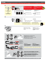
MODEL: EVO-ONE
DATE:02/2019
FORTIN.CA
SN: 000000 00000
MADE IN CANADA
© 2018 ALL RIGHTS RESERVED
2019
COMPATIBLE
MODULE
REQUIRED:
QR CODE
ON THE LABEL FIRMWARE VERSION
VERSION LOGICIELLE To add the rmware version and the options, use the
FLASH LINK UPDATER or FLASH LINK MOBILE tool,
sold separately.
Pour ajouter la version logicielle et les options,
utilisez l’outil FLASH LINK UPDATER
ou FLASH LINK MOBILE, vendu séparément.
MANUFACTURED
AFTER: 2019
MODULE
COMPATIBLE
REQUIS:
CODE QR SUR
L’ÉTIQUETTE 64.[06]
FABRIQUÉ APRÈS:
2019 VW MINIMUM
MODEL: EVO-ONE
DATE:02/2019
FORTIN.CA
SN: 000000 00000
MADE IN CANADA
© 2018 ALL RIGHTS RESERVED
2019
COMPATIBLE
MODULE
REQUIRED:
QR CODE
ON THE LABEL FIRMWARE VERSION
VERSION LOGICIELLE To add the rmware version and the options, use the
FLASH LINK UPDATER or FLASH LINK MOBILE tool,
sold separately.
Pour ajouter la version logicielle et les options,
utilisez l’outil FLASH LINK UPDATER
ou FLASH LINK MOBILE, vendu séparément.
MANUFACTURED
AFTER: 2019
MODULE
COMPATIBLE
REQUIS:
CODE QR SUR
L’ÉTIQUETTE 65.[04]
FABRIQUÉ APRÈS:
2019 VW MINIMUM
Golf MFD 09-2014 & +
Golf MFD 01-2014 to 08-2014
Page 1 / 12
STAND ALONE INSTALLATION
INSTALLATION STAND ALONE

This guide may change without notice. See www.fortin.ca for latest version.
Ce guide peut faire l’objet de changement sans préavis. Voir www.fortin.ca pour la récente version.
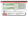
NOTES
D6 Push-to-Start
Push-to-Start
Program bypass option:
Programmez l’option du contournement:
UNIT OPTION
OPTION UNITE DESCRIPTION
C1
OEM Remote status (Lock/Unlock)
monitoring
Suivi des status (Verrouillage/Déverrouil-
lage) de la télécommande d’origine
Program bypass option
(If equiped with OEM alarm):
Programmez l’option du contournement
(Si équipé d’une alarme d’origine):
D2
Unlock before / Lock after (Disarm OEM
alarm)
Déverrouille avant / Verrouille après
(Désarme l’alarme d’origine)
Parts required (Not included) Pièce(s) requise(s) (Non incluse(s))
1x Fuse
2x Diodes
1x Fusible
2x Diodes
R-LINK PROGRAMMING TOOL REQUIRED
for key bypass programming.
Sold separately.
OUTIL DE PROGRAMMATION REQUIS
pour le contournement de clé.
Vendu séparément.
TB-VW 1x TB-VW (key bypass) Sold separately. 1x TB-VW (contournement de clé) Vendu séparément
Page 2 / 12

This guide may change without notice. See www.fortin.ca for latest version.
Ce guide peut faire l’objet de changement sans préavis. Voir www.fortin.ca pour la récente version.
All doors must be closed.
Toutes les portes doivent
être fermées
Brake ON
No tach
Ignition
before start
Hood Open
Frein Activé
Pas de Tach
Clé de contact
détectée avant
démarrage
Capot Ouvert
REMOTE STARTER DIAGNOSTICS
DIAGNOSTIQUE DU DÉMARREUR À DISTANCE
MODULE RED LED | DEL ROUGE DU MODULE
x2 ash :
x3 ash :
x4 ash :
x5 ash :
The vehicle will START.
Le véhicule DÉMARRE.
START
Press the OEM remote’s Lock Unlock Lock buttons
to remote-start (or remote-stop) the vehicle.
Appuyez sur les boutons Verrouillage
Dérrouillage Verrouillage de la télécommande
d'origine pour démarrer à distance (ou arrêter à
distance) le véhicule.
REMOTE STARTER FUNCTIONALITY | FONCTIONNALITÉS DU DÉMARREUR À DISTANCE
REMOTE STARTER WARNING CARD | CARTE D'AVERTISSEMENT DE DÉMARREUR À DISTANCE
CUT THIS WARNING CARD AND STICK IT ON A VISIBLE PLACE:
or use the package RSPB, Sold separately.
COUPEZ CETTE CARTE D'AVERTISSEMENT ET COLLEZ-LA À UN ENDROIT VISIBLE:
ou utilisez la trousse RSPB, vendue séparément.
THE VEHICLE CAN BE STARTED BY
EITHER: PRESSING THE LOCK BUTTON
ON THE OEM REMOTE 3 TIMES
CONSECUTIVELY OR BY A
SMARTPHONE. TURN ON THE SAFETY
SWITCH LOCATED UNDER THE
DASHBOARD BEFORE WORKING ON
THE VEHICLE.
LE VÉHICULE PEUT DÉMARRER SOIT: EN
APPUYANT 3 FOIS CONSÉCUTIVEMENT SUR
LE BOUTON VERROUILLAGE DE LA
TÉLÉCOMMANDE DU VÉHICULE OU PAR UN
TÉLÉPHONE INTELLIGENT. ACTIONNEZ EN
POSITION ‘ON’ LE COMMUTATEUR DE
SÉCURITÉ SITUÉ SOUS LE TABLEAU DE BORD
AVANT LES TRAVAUX D'ENTRETIEN.
DÉMARREUR À DISTANCE
REMOTE STARTER
WARNING | ATTENTION
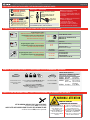
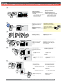
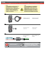
PARTS REQUIRED (NOT INCLUDED) | PIÈCES REQUISES (NON INCLUSES)
STAND ALONE CONFIGURATION | CONFIGURATION EN DÉMARREUR AUTONOME
OFF
ON
1x FLASH LINK UPDATER,
1x FLASH LINK MANAGER
1x FLASH LINK MOBILE
1x FLASH LINK MOBILE APP
OR
OU
1x
1x
HOOD PIN
VALET SWITCH
COMMUTATEUR
VALET
REMOTE START SAFETY OVERRIDE
SWITCH
CONTACT
DE
CAPOT
COMMUTATEUR DE SÉCURITÉ DE
DÉSACTIVATION DU DÉMARREUR
À DISTANCE
MANDATORY | OBLIGATOIRE Notice: the installation of safety
elements are mandatory.
The hood pin and the valet switch are
essential security elements and must
be installed.
Notice: l'installation des éléments de
sécurité est obligatoire.
Le contact de capot et le
commutateur de valet sont des
éléments de sécurité essentiels et
doivent absolument être installés.
Part #: RSPB available, Sold separately.
Pièce #: RSPB disponible, vendu séparément.
SOFTWARE | PROGRAMME
Smartphone AndroId or iOS with Internet
connection (provider charges may apply).
Téléphone Intelligent Android ou iOS
avec connection Internet (frais du
fournisseur Internet peuvent s’appliquer).
Microsoft Windows Computer
with Internet connection
Ordinateur Microsoft Windows
avec connection Internet
UN
Program bypass option
OEM Remote Stand Alone Remote Starter:
Programmez l’option du contournement
Démarreur à distance Autonome
avec télécommande d’origine :
D1.10
D1.1
By default, LOCK, LOCK, LOCK
Par défaut, VERROUILLE,VERROUILLE,VERROUILLE
LOCK, UNLOCK, LOCK
VERROUILLE,DÉVERROUILLE,VERROUILLE
OU
OR
UNIT OPTION
OPTION UNITE DESCRIPTION
UNIT OPTION
OPTION UNITE DESCRIPTION
D4
Hybrid mode
(Vehicle hybrid only)
Mode hybride
(vehicule hybride seulement)
Program bypass option with oem remote:
Programmez l’option du contournement
avec télécommande d'origine:
UNIT OPTION
OPTION UNITE DESCRIPTION
C1
OEM Remote Monitoring
Supervision de la
télécommande d'origine
Program bypass option with RF KIT antenna:
Programmez l’option du contournement
avec antenne RF:
Program bypass option
Vehicle hybrid only:
Programmez l’option du contournement
vehicule hybride seulement:
UNIT OPTION
OPTION UNITE DESCRIPTION
H1 to H6
H1 à H6
Supported RF Kits
and select RF Kit
Kit RF supportés
et sélectionnez le KIT RF
UN
Program bypass option
OEM Remote Stand Alone Remote Starter:
Programmez l’option du contournement
Démarreur à distance Autonome
avec télécommande d’origine :
D1.1 LOCK, UNLOCK, LOCK
VERROUILLE, DÉVERROUILLE,
VERROUILLE
Page 3 / 12

This guide may change without notice. See www.fortin.ca for latest version.
Ce guide peut faire l’objet de changement sans préavis. Voir www.fortin.ca pour la récente version.
DESCRIPTION | DESCRIPTION
OBD-II connector
Connecteur OBD-II
Under the steeing column
Sous la colonne de direction
VESCM - Electrical System Control Module
under dash driver side, above Driver Kick Panel
VESCM - Module de contrôle de système électrique
sous le tableau de bord côté conducteur, au-dessus
du panneau latérale. Clips
Pull the clips to release the cover
of the connector. Soulever les clips
pour sortir le couvert du connecteur.
(+) BRAKE
CONTROL
(~) CAN
LOW2
(~) CAN
HIGH2
Start/Stop2
Start/Stop1
(+) Ignition
1
(+) 12V
CAN HIGH2
CAN LOW2
14
6
(-)HAZARD
Page 4 / 12

This guide may change without notice. See www.fortin.ca for latest version.
Ce guide peut faire l’objet de changement sans préavis. Voir www.fortin.ca pour la récente version.
Yellow In A1
Purple In A2
Purple/White In A3
Green Out A4
White Out A5
Orange In A6
Orange/Black In A7
Dk.Blue In A8
Red/Blue In A9
Lt.Blue/Black A10
Black Out A11
Pink Out A12
Yellow/Black In A13
Brown/White Out A14
Pink/Black Out A15
Purple/Yellow A16
Green/White A17
Green/Red A18
White/Black A19
Lt.Blue A20
C5 Brown
C4 Gray/Black
C3 Gray
C2 Orange/Brown
C1 Orange/Green
D6 White/Red
D5 White/Blue
D4 White/Green
D3 Yellow/Red
D2 Yellow/Blue
D1 Yellow/Green
AC
D
AUTOMATIC TRANSMISSION WIRING CONNECTION | SCHÉMA DE BRANCHEMENT TRANSMISSION AUTOMATIQUE
A2
A3
A4
A5
A6
A7
A8
A9
A10
A11
A12
A13
A14
A15
A16
A17
A18
A19
A20
C5
C4
C3
C2
C1
D6
D5
D4
D3
D2
D1
A1
D1
D4
D5
D6
C5
(~) TX(~) TX
A19
A18
A17
(-)Hazards
A12
A11
(~) RX(~) RX
A9
A7
A6
A5
A4
A1
RS1 Ground | Masse
Ground
Masse
RS2 IN 12V Battery(+)
WITH | AVEC DATA-LINK:
Direct connection
Branchement directe
RF-KIT REMOTE
STARTER
KIT-RF DÉMARREUR
À DISTANCE
WITH RF-KIT
AVEC KIT-RF
OPTIONAL RF KIT
KIT RF OPTIONNEL
B
B4
B3
B2
B1
Cut | Coupez Red
Cut | Coupez Black
Blue
White
WITHOUT RF-KIT:
SANS KIT RF:
B4 Red12V Battery(+)
B3 BlackGround | Masse
Ground
Masse
CAN 1 LOW
CAN 1 HIGH
CAN 2 LOW
CAN 2 HIGH
(-) Unlock
(-) Lock
(-) Lock/Unlock input external
control | Contrôle du
(-) verrouillage devérrouillage
entrée externe
Start / Stop external control
Contrôle de démarrage/arrêt
externe
Start/Stop external
Hood pin
SAFETY OVERRIDE SWITCH
COMMUTATEUR DE SÉCURITÉ
Hood pin only required on vehicles not
equipped with a factory hood pin.
Commutateur de capot requis seulement
si le véhicule n'est pas équipé de cette
composante.
GOLF
(~) CAN1
LOW
(~) CAN1
HIGH
Orange/
Brown
Orange/
Brun
Orange/
Green
Orange/
Vert
Under the steering
column
Black connector -
Back view
Sous la colonne de
direction
Connecteur Noir -
Vue de dos
(-)START/
STOP2
(-)START/
STOP1
C3 C4
OBDII
Front view
Vue de face
1
910
2 3 4 5 7 8
11 12 13 14 15
61234678
910111213141516
5
Purple/
Blue
Mauve/
Bleu
Purple
Mauve
14
6
6
14
C2 C1
Orange/
Black
Orange/
Noir
Orange/
Brown
Orange/
Brun
(~)CAN2
HIGH
(~)CAN2
LOW
16
1A Diode
1A Diode
TRANS-
PONDER
WIRE
Back view Black 2-Pin
connector
transponder connector
Vue de dos Connecteur Noir
de 2 pins connecteur du
transpondeur
12
CUT
Pin2
Red/
Brown
Rouge/
Brun
(+)12V
7
Brown cover Under the dash
Driver side, Black 73-PINS
connector - Back view
Couvert Brun, Sous le
tableau de bord côté
chauffeur Connecteur Noir
de 73 pins- Vue de dos
VESCM - Electrical System Control Module
under dash driver side, above Driver Kick Panel
VESCM - Module de contrôle de système électrique
sous le tableau de bord côté conducteur, au-dessus
du panneau latérale.
58
54 3 21
10 9 8 7
1314
1516171819202122232425262728
12 11 6
293031323334353637
3839
40414243444546474849505152535455565759 58606162
67 66 65 64 63
7172 70 69 68
73
(+) BRAKE
CONTROL
Black/Red
Noir/Rouge
(-)HAZARD
OPTIONAL
OPTIONNEL
A14
Brown/Red
Brun/Rouge
42
5 AMP
fuse
A15
(-)Start/Stop
NE PAS RALLONGER
LES FILS
(6 pouces max.)
DO NOT EXTEND
THE WIRES
(6 inches max).
Ground
Masse
TB-VW
SOLD SEPARATELY
VENDU SÉPARÉMENT
White or Lt.Blue/Black
White/Red or Green
White/Green
or Green/Black
Blue or Lt.Blue
Black
Red
(~) RX
(~) TX
Ground
(+)12V
D2
(+)12V
(+) Brake control
D3
RS3 IN/OUT (+)Igni�on Can be required
Peux être requis
(+)IGNITION OUTPUT
Page 5 / 12

CONTINUED NEXT PAGE | CONTINUEZ À LA PAGE SUIVANTE
WARNING:
Close and open the
driver door.
ATTENTION:
Fermez et ouvrez la
porte conducteur.
USE THE R-LINK* TOOL FOR
PROGRAMMING
UTILISEZ L’OUTIL R-LINK* POUR LA
PROGRAMMATION
*Sold separately *Vendu séparément
RLINK
SOLD SEPARATELY
VENDU SÉPARÉMENT
Connect the R-LINK instead
of the TB-VW.
Branchez le R-LINK à la place du
TB-VW.
White or Lt.Blue/Black
Blue or Lt.Blue
Black
Red
(~) RX
(~) TX
Ground
(+)12V
White/Red or Green
White/Green
or Green/Black
1
3
4
5
1
1
2
With the remote beside the
antenna ring, proceed with the
programming on the next pages.
Avec la télécommande
coincée sur l'anneau de
l'antenne, procéder
à la programmation aux pages
suivantes.
Place the transponder’s ring
in front of the remote control.
Placer l’anneau du transpondeur
devant la télécommande.
Take out the battery from the
remote control.
retirer la batterie de la
télécommande.
This guide may change without notice. See www.fortin.ca for latest version.
Ce guide peut faire l’objet de changement sans préavis. Voir www.fortin.ca pour la récente version.
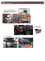
DCRYPTOR PROGRAMMING PROCEDURE | PROCÉDURE DE PROGRAMMATION AVEC DCRYPTOR
Parts required (not included) Pièces requises (non incluses)
1x FLASH LINK UPDATER,
1x FLASH LINK MANAGER
1x FLASH LINK MOBILE
1x FLASH LINK MOBILE APP
SOFTWARE | PROGRAMME
Smartphone Android or iOS with Internet connection
(Internet provider charges may apply)
Téléphone Intelligent Android ou iOS avec connection
Internet (des frais du fournisseur Internet peuvent s’appliquer)
OR
OU
Microsoft Windows Computer with Internet connection
Ordinateur Microsoft Windows avec connection Internet
1x1x
BEFORE PROGRAMMING SET THE UNIT OPTIONS AND SAVE. | AVANT LA PROGRAMMATION CONFIGURER LES OPTIONS DE L'UNITÉ ET SAUVEGARDER.
Page 6 / 12

Press and hold the
programming button.
Appuyez et gardez enfoncé
le bouton de programmation.
Release the programming
button.
Relâchez le bouton de
programmation.
The BLUE LED will turn OFF. La DEL BLEUE s'éteint.
The RED LED will turn ON. La DEL ROUGE s'allume.
Wait, Attendez,
CONTINUED NEXT PAGE | CONTINUEZ À LA PAGE SUIVANTE
1
7
8
9
11
10
6
Insert the required
remaining connectors. Insérez les connecteurs
requis restants.
The BLUE LED will flash
rapidly.
La DEL BLEU clignotera
rapidement.
Press and release the
programming button once
(1x).
Appuyez et relâchez 1 fois
le bouton de programmation.
Wait, Attendre,
will
turn off.
The BLUE LED
s'éteint.
La DEL BLEUE
IGN ON
x1
PRESS Press the Push-to-Start
button to turn ON the
ignition.
Appuyez 1 fois sur le bouton
démarrage (Push-to-Start) pour
allumer l'ignition.
HOLD
x1
PRESS
PRESS - HOLD
OFF
ON
WAIT
3 SEC.
RELEASE
RELEASE
Release the programming
button when the LED is
BLUE.
Relâchez le bouton de
programmation quand la DEL
est BLEU.
If the LED is not solid BLUE
disconnect the 4-Pin connector
(Data-Link) and go back to step 1.
Si le DEL n'est pas BLEU
débranchez le connecteur 4 pins
(Data-Link) et allez au début de
l'étape 1.
ON BLUE
BLEU
ON ON
Press and hold the
programming button:
Connect the 4-Pin Data-link
connector.
The BLUE, RED, YELLOW and
BLUE & RED LEDs will
alternatively illuminate.
Appuyez et maintenir
enfoncé le bouton de
programmation: Branchez le
connecteur Data-Link à 4-Broches.
Les DELs BLEUE, ROUGE,
JAUNE et BLEUE & ROUGE
s'allumeront alternativement.
x1
HOLD
x1
PRESS
FLASH
RAPIDLY
OFF
IGNITION ON PRESS X1
WAIT
IGNITION ON
IGNITION OFF
ON
This guide may change without notice. See www.fortin.ca for latest version.
Ce guide peut faire l’objet de changement sans préavis. Voir www.fortin.ca pour la récente version.
KEY BYPASS PROGRAMMING PROCEDURE 2/4 | PROCÉDURE DE PROGRAMMATION CONTOURNEMENT DE CLÉ 2/4
Page 7 / 12

Wait, Attendez,
Wait, Attendez,
the RED LED to turn ON. La DEL ROUGE s'allume.
the YELLOW LED will flash
once.
La DEL JAUNE clignote
une fois.
Wait, do not touch the
vehicle or the module.
Attendez, ne touchez
pas au véhicule ou au
module.
The BLUE, RED and YELLOW
LEDs will rapidly alternate.
Les DELs BLEUE, ROUGE
et JAUNE alternent
rapidement.
Wait for the RED and YELLOW
LEDs to slowly alternate.
Attendez que les DELs ROUGE
et JAUNE alternent doucement.
1
1
WAIT,
this processe may take up
to 5 minutes
Attendez,
ce processus peut prendre
jusqu’à 5 minutes
CONTINUED NEXT PAGE | CONTINUEZ À LA PAGE SUIVANTE
If the RED LED flashes slowly, the
programming has failed, go back to
step1 and start the programming over.
Si la DEL ROUGE clignote
lentement, la programmation a
échoué, recommencez à l'étape 1.
12
13
14
OFF
x1 Press the Push-to-Start
button once to turn off the
ignition.
Appuyez 1 fois sur le
bouton démarrage (Push-
to-Start) pour éteindre
l'ignition.
PRESS
...
...
...
ON
ON
ON
OFF
ON
EVO-ALL
Disconnect all the connectors and after
the Data-Link (4-pins) connector.
Débranchez tous les connecteurs et ensuite
le connecteur Data-Link (4-pins).
*Pièces requises (non incluses)
Use the tool:
FLASH LINK UPDATER or
FLASH LINK MOBILE
to visit the DCryptor menu.
Utilisez l'outil:
FLASH LINK UPDATER ou
FLASH LINK MOBILE
pour visiter le menu DCryptor.
*Parts required (not included)
FLASH LINK UPDATER*
FLASH LINK MOBILE*
FLASH LINK MANAGER*
SOFTWARE | PROGRAMME
Microsoft Windows
Computer with
Internet connection*
Ordinateur Microsoft
Windows avec
connection Internet*
VEHICLE'S OBDII
CONNECTOR
CONNECTEUR OBDII
DU VÉHICULE
OR
OU
Smartphone*
(Internet provider
charges
may apply)
Téléphone
Intelligent*
(des frais du
fournisseur
Internet peuvent
s’appliquer)
AFTER DCRYPTOR PROGRAMMING COMPLETED
Go back to the vehicle and reconnect the 4-Pin (Data-Link)
connector and after, all the remaining connector.
APRÈS LA PROCÉDURE DE PROGRAMMATION
DCRYPTOR COMPLETÉE : retournez au véhicule et
rebranchez le connecteur 4-pins (Data-Link)
et après, tous les connecteurs du EVO-ALL.
EVO-ALL
15
16
16
This guide may change without notice. See www.fortin.ca for latest version.
Ce guide peut faire l’objet de changement sans préavis. Voir www.fortin.ca pour la récente version.
KEY BYPASS PROGRAMMING PROCEDURE 3/4 | PROCÉDURE DE PROGRAMMATION CONTOURNEMENT DE CLÉ 3/4
Page 8 / 12

REMOTE STARTER / ALARM VERIFICATION
PROCEDURE | PROCÉDURE DE VÉRIFICATION
DU DÉMARREUR À DISTANCE / ALARME
Test the remote starter. Remote start the vehicle.
Testez le démarreur à distance. Démarrez le véhicule
à distance.
The module is now programmed.
Le module est programmé.
REMOTE STARTER / ALARM VERIFICATION
PROCEDURE | PROCÉDURE DE VÉRIFICATION
DU DÉMARREUR À DISTANCE / ALARME
Test the remote starter. Remote start the vehicle.
Testez le démarreur à distance. Démarrez le véhicule
à distance.
The module is now programmed.
Le module est programmé.
Insert the battery into the
remote control.
Insérer la batterie de
la télécommande.
Take out the remote control
from the transponder’s ring.
Retirer la télécommande de
l’anneau du transpondeur.
1
18
1
19
SI LA PROGRAMMATION EST INTERROMPUE
DURANT SON PROCESSUS, COMME PAR UN
DÉBRANCHEMENT DU MODULE OU PAR LA
FERMETURE DE LA CLÉ DE CONTACT, IL EST
POSSIBLE QUE LE VÉHICULE NE PUISSE PLUS
DÉMARRER NORMALEMENT, VOUS DEVREZ
DÉBRANCHER ET REBRANCHER LA BATTERIE
DU VÉHICULE POUR CORRIGER LA SITUATION.
IF PROGRAMMING IS INTERRUPTED DURING
THE PROCESS, SUCH AS A MODULE IS
DISCONNECTED OR BY TURNING OFF THE
IGNITION WITH THE KEY, IT IS POSSIBLE THAT
THE VEHICLE WILL NO LONGER START
NORMALLY, YOU MUST DISCONNECT AND
RECONNECT THE VEHICLE BATTERY TO
CORRECT THE SITUATION.
TB-VW
SOLD SEPARATELY
VENDU SÉPARÉMENT
Connect the TB-VW instead
of the R-LINK.
Branchez le TB-VW à la place
du R-LINK.
White or Lt.Blue/Black
Blue or Lt.Blue
Black
Red
(~) RX
(~) TX
Ground
(+)12V
White/Red or Green
White/Green
or Green/Black
NOTE NOTE
1
20
This guide may change without notice. See www.fortin.ca for latest version.
Ce guide peut faire l’objet de changement sans préavis. Voir www.fortin.ca pour la récente version.
KEY BYPASS PROGRAMMING PROCEDURE 4/4 | PROCÉDURE DE PROGRAMMATION CONTOURNEMENT DE CLÉ 4/4
Page 9 / 12

This guide may change without notice. See www.fortin.ca for latest version.
Ce guide peut faire l’objet de changement sans préavis. Voir www.fortin.ca pour la récente version.
REMOTE STARTER FUNCTIONALITY | FONCTIONNALITÉS DU DÉMARREUR À DISTANCE
Remote start
Démarrez
the vehicle.
à
distance.
START
All doors must
be closed.
Toutes les
portes doivent
être fermées
UNLOCK
Enter
Entrez
the vehicle
with the Intelligent
SmartKey.
dans le
véhicule avec la
clé intelligente
(SmartKey) sur
vous
The vehicle can
now be put in to
gear and driven.
Vous êtes
maintenant prêt à
embrayer et
prendre la route.
Insert
Insérez
the key in
the Key port
la clé
dans le Key Port
Insert
START
All doors must
be closed.
Toutes les
portes doivent
être fermées
UNLOCK
Enter
Entrez
the vehicle
with the Intelligent
SmartKey.
dans le
véhicule avec la
clé intelligente
(SmartKey) sur
vous
The vehicle can
now be put in to
gear and driven.
Vous êtes
maintenant prêt à
embrayer et
prendre la route.
PUSH
START
Vehicles with key port.
Véhicules avec key port.
Vehicles with Push-to-Start.
Véhicules avec bouton Push-to-Start.
Unlock the doors with
either:
• The OEM remote
• The remote-starter
remote.
Déverrouillez les portes
avec soit:
• la télécommande
d'origine
• la télécomande du
démarreur à distance.
Unlock the doors with
either:
• The OEM remote
• The remote-starter
remote.
Déverrouillez les portes
avec soit:
• la télécommande
d'origine
• la télécomande du
démarreur à distance.
Remote start
Démarrez
the vehicle.
à
distance.
Page 10 / 12

OPTIONAL FORTIN RF KIT SERIES 4 OR SERIES 9 PROGRAMMING | PROGRAMMATION DU KIT RF FORITN SÉRIE 4 OU SÉRIE 9 (OPTIONNELLE)
Program bypass option:
Programmez l’option du contournement : H2
☑Supported RF-KITS enable
☑ H2 Fortin 2
☑Activation KITS RF supporté
☑ H2 Fortin 2
PROGRAM BYPASS OPTION | PROGRAMMATION DES OPTIONS DE CONTOURNEMENT
x4
PRESS
The module must
be programmed
on the vehicle.
Le module doit
être programmé
sur le véhicule.
MAKE SURE
THE IGNITION
KEY HAS BEEN
IN THE OFF
POSITION FOR
AT LEAST 5
SECONDS.
ASSUREZ-VOUS
QUE LA CLÉ DE
CONTACT EST
À LA POSITION
OFF DEPUIS AU
MOINS 5
SECONDES.
Press and
release the
brake pedal
four times.
Appuyez et
relâchez
quatre fois
la pédale de
frein.
The LED will
turn ON
solide.
Le témoin
s’allumera.
The LED
will flash
rapidly.
Le témoin
clignotera
rapidement.
The LED
will turn off
each time.
Le témoin
s’inteindra
chaque fois
The LED
will turn Off.
The 3
LED will
turn ON
solid.
Les 3 DELs
s’allumeront
solide.
The
YELLOW
LED will
turn ON
solid.
La DEL JAUNE
s’allumera solide.
The
YELLOW
LED will
turn Off.
La DEL JAUNE
s’éteindra.
The LED will
flash rapidly.
Le témoin
clignotera
rapidement.
The 3 LED
will turn off
each time.
Les 3 DELs
s’éteindront
chaque fois.
Le témoin
s’éteint
The 3 LED
will turn off.
Les 3 DELs
s’éteindront.
SUR CHACUNE DES
TÉLÉCOMMANDES
ON EACH
TRANSMITTER
The
YELLOW
LED will
turn ON
solid.
La DEL JAUNE
s’allumera solide.
OFF OFFON ON 4X BRAKES
1 2 53 6
4
4 BUTTONS
4 BOUTONS
1 BUTTON
1 BOUTON
PRESS APPROX.
12 SEC. AND WAIT
FOR THE BLUE LED
TO TURN OFF THEN
BACK ON SOLID
THEN RELEASE.
PRESS AND
RELEASE
APPUYEZ ET
RELÂCHEZ
PRESS AND
RELEASE
APPUYEZ ET
RELÂCHEZ
APPUYEZ ET TENEZ
ENFONCÉ LE POUR
APPROX. 12 SEC, LA
DEL BLEUE
S'ÉTEINT ET
S'ALLUME SOLIDE,
ENSUITE
RELÂCHEZ.
The LED will
turn off each
time.
Le témoin
s’éteindra
chaque fois.
OFF
IGN ON
x1
PRESS
OFF
x1
PRESS
Do not press the
brake pedal.
Press the
Push-to-Start
button once to
turn on the
ignition.
Press the
Push-to-Start
button once to
turn off the
ignition.
Ne pas appuyer
sur la pédale de
frein. Appuyez
une fois sur le
bouton
démarrage
pour allumer
l'ignition.
IGN ON
x1
PRESS
Do not press the
brake pedal.
Press the
Push-to-Start
button once to
turn on the
ignition.
Ne pas appuyer
sur la pédale de
frein. Appuyez
une fois sur le
bouton
démarrage
pour allumer
l'ignition.
Appuyez une
fois sur le
bouton
démarrage
pour éteindre
l'ignition.
OFF
x1
PRESS
Press the
Push-to-Start
button once to
turn off the
ignition.
Appuyez une
fois sur le
bouton
démarrage
pour éteindre
l'ignition.
5-STANDALONE_RFKIT
This guide may change without notice. See www.fortin.ca for latest version.
Ce guide peut faire l’objet de changement sans préavis. Voir www.fortin.ca pour la récente version.
OPTIONAL RF-KIT PROGRAMMING | PROGRAMMATION KIT RF OPTIONELLE
Page 11 / 12

ALL
Service No : 000 102 04 2536
Date: xx-xx
INTERFACE MODULE
Made in Canada
PATENTS PENDING US: 2007-228827-A1
www.fortinbypass.com
HARDWARE VERSION
FIRMWARE VERSION
Module label | Étiquette sur le module
Notice: Updated Firmware and Installation Guides
Updated fi rmware and installation guides are posted on our web site on a regular
basis. We recommend that you update this module to the latest fi rmware and
download the latest installation guide(s) prior to the installation of this product.
Notice: Mise à jour microprogramme et Guides d’installations
Des mises à jour du Firmware (microprogramme) et des guides d’installation
sont mis en ligne régulièrement. Vérifi ez que vous avez bien la dernière version
logiciel et le dernier guide d’installation avant l’installation de ce produit.
WARNING
The information on this sheet is provided on an (as is) basis with no representation or warranty of accuracy whatsoever.
It is the sole responsibility of the installer to check and verify any circuit before connecting to it. Only a computer safe
logic probe or digital multimeter should be used. FORTIN ELECTRONIC SYSTEMS assumes absolutely no liability or
responsibility whatsoever pertaining to the accuracy or currency of the information supplied. The installation in every case
is the sole responsibility of the installer performing the work and FORTIN ELECTRONIC SYSTEMS assumes no liability
or responsibility whatsoever resulting from any type of installation, whether performed properly, improperly or any other
way. Neither the manufacturer or distributor of this module is responsible of damages of any kind indirectly or directly
caused by this module, except for the replacement of this module in case of manufacturing defects. This module must be
installed by qualifi ed technician. The information supplied is a guide only. This instruction guide may change without
notice. Visit www.fortinbypass.com to get the latest version.
MISE EN GARDE
L’information de ce guide est fournie sur la base de représentation (telle quelle) sans aucune garantie de précision et
d’exactitude. Il est de la seule responsabilité de l’installateur de vérifi er tous les fi ls et circuits avant d’effectuer les connexions.
Seuls une sonde logique ou un multimètre digital doivent être utilisés. FORTIN SYSTÈMES ÉLECTRONIQUES n’assume
aucune responsabilité de l’exactitude de l’information fournie. L’installation (dans chaque cas) est la responsabilité de
l’installateur effectuant le travail. FORTIN SYSTÈMES ÉLECTRONIQUES n’assume aucune responsabilité suite à
l’installation, que celle-ci soit bonne, mauvaise ou de n’importe autre type. Ni le manufacturier, ni le distributeur ne se
considèrent responsables des dommages causés ou ayant pu être causés, indirectement ou directement, par ce module,
excepté le remplacement de ce module en cas de défectuosité de fabrication. Ce module doit être installé par un technicien
qualifi é. L’information fournie dans ce guide est une suggestion. Ce guide d’instruction peut faire l’objet de changement
sans préavis. Consultez le www.fortinbypass.com pour voir la plus récente version.
Copyright © 2006-2018, FORTIN AUTO RADIO INC ALL RIGHTS RESERVED PATENT PENDING
TECH SUPPORT
Tél: 514-255-HELP (4357)
1-877-336-7797
ADDENDUM GUIDE WEB UPDATE | MISE À JOUR INTERNET
www.fortinbypass.com
EVO-ALL
Page 12 / 12
-
 1
1
-
 2
2
-
 3
3
-
 4
4
-
 5
5
-
 6
6
-
 7
7
-
 8
8
-
 9
9
-
 10
10
-
 11
11
-
 12
12


Fortin EVO-ONE Volkswagen Golf 2016 Guide d'installation
- Taper
- Guide d'installation
dans d''autres langues
Documents connexes
-
Fortin 102991 Guide d'installation
-
Fortin 106491 Guide d'installation
-
Fortin 82371 Guide d'installation
-
Fortin 2017 Guide d'installation
-
Fortin 2024 Guide d'installation
-
Fortin 102941 Guide d'installation
-
Fortin 2013 Volkswagen Guide d'installation
-
Fortin 97331 EVO-ALL Guide d'installation
-
Fortin 103031 2021 Chrysler 300 Push Button Remote Starters and Alarm Systems Guide d'installation
-
Fortin 97391 Guide d'installation