Tetra 24V GEPS24-200U-GLX2 Signage Power Supply Guide d'installation
- Taper
- Guide d'installation

Installation Guide
FOR UL ONLY
Power Supply Features
• Supports all 24 VDC Tetra Products
• UL: Class 2
• IEC: SELV
• 100-277 VAC Input
• Two 100 Watt Output Banks
Save These Instructions
Use only in the manner intended by the manufacturer.
If you have any questions, contact the manufacturer.
Electrical Requirements
• Limited to use in dry and damp locations.
• The suitability of rain enclosure shall be determined if
intended for wet location.
• The grounding and bonding of the LED Driver shall be done
in accordance with National Electric Code (NEC) Article 600.
• Follow all National Electric Codes (NEC) and local codes.
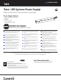
Tetra® LED Systems Power Supply
GEPS24-200U-GLX2 (100-277 VAC input/24VDC output/200W)
2424
Volt
BEFORE YOU BEGIN
Read these instructions completely and carefully.
EN
For the latest North American install guides for your product go to: https://products.LED.com/led-signage-lighting
For the latest European install guides for your product go to: https://products.LED.com/eu
BG Българската версия на инструкциите за инсталаця и
информация за безопасност могат да бъдат намерени
на следния адрес: https://products.LED.com/eu
CS Návod k montáží a bezpečnostní informace v češtině
najdete zde: https://products.LED.com/eu
DA Den danske version af installationsvejledningen og
sikkerhedsoplysninger kan ndes på følgende placering:
https://products.LED.com/eu
DE Die deutsche Version der Installationsanleitung und
Sicherheitsinformationen nden Sie in folgendem Verzeic:
https://products.LED.com/eu
EL Μπορείτε να βρείτε την ελληνική εκδχή των οδηγιών
νγκατάστασης και των πληροφοριών ασφάλειας στην
εξής τοποθεσία: https://products.LED.com/eu
ES La versión española de las instrucciones de instalación y
la información sobre seguridad puede encontrarse en la
siguiente ubicación: https://products.LED.com/eu
ET Eestikeelse paigaldusjuhendi ja ohutusnñuded leiate
aadressilt: https://products.LED.com/eu
FI Asennusohjeiden ja turvallisuustietojen suomenkielinen
versio löytyy seuraavasta paikasta: https://products.LED.
com/eu
FR La version française des instructions d’installations et
information de sécurité est disponible à l’adresse suivante:
https://products.LED.com/eu
HR Hrvatska verzija priručnika za ugradnju i sigurnosnih
informacija nalazi se na sljedečoj lokaciji: https://products.
LED.com/eu
HU A telepítési útmutató és a biztnosági információk magyar
nyelvű változata az alábbi címen található: https://
products.LED.com/eu
IT La versione italiana del manuale di installazione e sicurezza
può essere reperita nella seguente sezione: https://
products.LED.com/eu
LT Lietuvišką diegimo instrukcijos ir saugos informacijos
versiją galima rasti šioje vietoje: https://products.LED.
com/eu
LV Uzstādīšanas instrukciju un drošības informāciju latviešu
valodā var atrast šeit: https://products.LED.com/eu
NL De Nederlandse versie van de installatie-instructies en
veiligheidsinformatie kan op de volgende locatie worden
gevonden: https://products.LED.com/eu
PL Polską wersję instrukcji instalacji oraz informacje dotyczące
bezpieczeństwa można znaleźć w następującej lokalizacji:
https://products.LED.com/eu
PT A versão em Português das instruções de instalação e
das informações de segurança pode ser encontrada na
seguinte localização: https://products.LED.com/eu
RO Versiunea în limba română a instrucţiunilor de instalare şi a
informaţiilor de siguranţă pot găsite la: https://products.
LED.com/eu
SV Ni hittar den svenska versionen av
installationsanvisningarna och säkerhetsinformationen på
följande plats: https://products.LED.com/eu
SL Previdnostna opozorila in varnostne informacije so na
zadnji strani vodnika za namestitev. Pred začetkom
namestitve izdelka jih skrbno preberite: https://products.
LED.com/eu
SK Slovenskú verziu montažnej príručky a bezpečnostnŷch
instrukcií nájdete na nasledujúcej lokalite: https://products.
LED.com/eu

Tetra® Power Supply GEPS24-200U-GLX2 Installation Guide
2
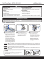
Power Supply Installation
Connect the supply wire that is attached
to your LED system to the red (+)
and black (-) output wires of the LED
driver as outlined in the “Electrical
Connections” section of your LED
system’s Installation Instructions.
Remove the junction box cover and
carefully remove knockout for AC line
input wires. Install appropriate electrical
ttings in the knockout holes for wire
protection. Securely mount the power
supply with the base in contact with the
mounting surface in accordance with
the power supply spacing requirements
described above. If used in a wet
location, the power supply and electrical
connections shall be protected from
weather by a suitable rain enclosure, and
not subject to saturation with water or
other liquids. If not protected from the
weather, the output connections may be
sealed with electrical grade silicone.
Connect the AC line to the black
(line) and white (neutral) input
wires of the LED driver using
18-14 AWG (0.82-2.08 mm2) twist-on
wire connectors. Ground LED driver by
connecting green wire to grounding
screw. Replace junction box cover.
Green
To LED system
Output wires
NOTE: To avoid overloading this
power supply with LED modules,
please refer to the specic module
loading guides.
FOR UL ONLY
NOTE: For CSA approval, a disconnect/toggle switch of appropriate rating needs to be placed within 29.5 ft. (9 m) of primary side
of the power supply. The minimum rating of the switch must be either 120 or 220 Volts AC. The switch must also support twice the
amount of input current.
FOR UL ONLY
NOTE: When installing power supply, connect to the appropriate sized building breaker or disconnect device for line and neutral
connections, in accordance with local, state or country regulations.
FOR UL ONLY
NOTE: The grounding and bonding of the power supply and overall sign shall be done in accordance with National Electric Code
(NEC) Article 600.
WARNING / AVERTISSEMENT
RISK OF ELECTRIC SHOCK
• Disconnect power at fuse box or circuit breaker before servicing or
installing product.
• Properly ground Tetra® power supply.
RISK OF FIRE
• Minimum 4 in. to side and 1 in. spacing in compartment surrounding
component required.
• Use only approved wire for input/output connection. Minimum size
18 AWG (0.82 mm2).
• Follow all local codes.
• Application considerations potentially requiring additional spacing
include high ambient temperature seen by the power supply, poor
contact with a heat dissipating material, inadequate ventilation, or
direct exposure to sun.
RISQUES DE DÉCHARGES ÉLECTRIQUES
• Coupez l’alimentation électrique à la boîte de fusibles ou au disjoncteur avant
l’entretien ou l’installation du produit.
• Assurez-vous de correctement mettre à terre le bloc d’alimentation Tetra®.
RISQUES D’INCENDIE
• Minimum 4 po sur le côté et espacement de 1 po dans le compartiment
entourant le composant requis.
• N’utilisez que des ls approuvés pour les entrées/sorties de connexion. Taille
minimum 18 AWG (0.82 mm2).
• Respectez tous les codes locaux.
• Certaines applications pourraient requérir un espacement additionnel, p.
ex. une température ambiante élevée autour du bloc d’alimentation, un
mauvais contact avec une matière dissipatrice de chaleur, une ventilation
inadéquate ou une exposition directe au soleil.
OPTIONAL
A Weather Box (GEXNWB2) may be used to house and seal Class 2
connections.
A) Insert wire connectors into weather box. Fill with electrical grade
silicone and close box.
B) Secure the weather box using a #6 or #8 (M2 or M3) screw.
Weather box
can be painted
CAUTION / ATTENTION
RISK INJURY
• While performing installations described, gloves, safety glasses or
goggles should be worn.
RISQUES DE BLESSURE
• Lors de l’exécution des installations décrites, des gants, des lunettes de sécurité
ou des lunettes de protection doivent être portées.
1 2 3
A B

Tetra® Power Supply GEPS24-200U-GLX2 Installation Guide
LED.com
© 2023 Current Lighting Solutions, LLC. All rights reserved. Information and specications subject to change
without notice. All values are design or typical values when measured under laboratory conditions.
Page 3 of 3
(Rev 06/20/23)
SIGN286 | DOC-2000005
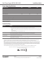
Power Supply Specications
Performance Data Min Nominal Max
Input Voltage (VAC) 108 100-277 305
Input Frequency (Hz) – 50/60 –
Input Current (A) – – 2.2
THD** – – 20
PF** 0.9 – –
Output Voltage (VDC) 24.0 24.5 25.0
Output Current (ADC) – – 4.0
Output Power (W) – – 200
Environmental Operating Temperature Range -40°C +25°C +60°C*
Environmental Humidity (non-condensing) 10% – 95%
Environmental Storage Temperature Range -40°C – +85°C
Dimensions 19.5” x 2.4” x 1.6” (495.5 mm x 61.6 mm x 40.2 mm)
Conforms to the following standards:
This product is intended to be used as a lamp control gear that is installed after the mains control switch.
Symptom Solution
All letters are OFF • Recycle AC power, turn it off, then turn on again.
• If still off, check the power supply DC output voltage using a voltmeter. It should be nominally 24V.
» If there is DC output, inspect and correct all DC wire damage/polarity issues; If no issue is found, replace the OFF-module
string.
» If there is no DC output, have a licensed electrician check the input AC voltage and if there is correct AC voltage, replace
the power supply.
» If there is no AC voltage, correct the upstream AC issue.
Some LEDs appear dim • Ensure the overall length of the Tetra® LED System does not exceed the maximum load.
• Ensure the length of supply wire is equal to or below the recommended remote mounting distance.
Some of the letters
are not illuminated
• Inspect and correct the wires of the non-illuminated letters for damage/polarity issues; If no issues are found, see the
troubleshooting solution for “All letters are OFF.”
Shadows • Re-route supply wire and secure to the back of the can with electrical grade RTV silicone. Adjust wire connector orientation
so that it does not cover any LEDs.
• Adjust LED layout to ensure uniformity of illumination of the face of the letter.
Troubleshooting
This device complies with part 15 of the FCC Rules. Operation is subject to the following two conditions: (1) This device may not cause harmful
interference, and (2) this device must accept any interference received, including interference that may cause undesired operation.
Note: This equipment has been tested and found to comply with the limits for a Class A digital device, pursuant to part 15 of the FCC Rules. These
limits are designed to provide reasonable protection against harmful interference when the equipment is operated in a commercial environment.
This equipment generates, uses, and can radiate radio frequency energy and, if not installed and used in accordance with the instruction manual,
may cause harmful interference to radio communications. Operation of this equipment in a residential area is likely to cause harmful interference
in which case the user will be required to correct the interference at his own expense.
This Class [A] RFLD complies with the Canadian standard ICES-005. Ce DEFR de la classe [A] est conforme à la NMB-005 du Canada.
*Maximum case temperature is 80°C
**At 120VAC - 277VAC Full Load
-
 1
1
-
 2
2
-
 3
3


Tetra 24V GEPS24-200U-GLX2 Signage Power Supply Guide d'installation
- Taper
- Guide d'installation
dans d''autres langues
Documents connexes
-
Tetra Atom LED Signage Guide d'installation
-
-
-
-
-
-
-
-
-