Maytag MDG28PNCGW Installation Instructions Manual
- Catégorie
- Sèche-linge électriques
- Taper
- Installation Instructions Manual

INSTALLATION
INSTRUCTIONS
CommerCial He Dryer
Gas
INSTRUCTIONS
D’INSTALLATION
sèCHe-linGe He CommerCial
À Gaz
INSTRUCCIONES
DE INSTALACIÓN
seCaDora He ComerCial
a Gas
ISTRUZIONI
D’INSTALLAZIONE
asCiuGatriCe He CommerCiale
a Gas
www.maytagcommerciallaundry.comW10590742A
MDG28PN
MDG28PD

2
TABLE OF CONTENTS
Page
Dryer Safety ............................................................................ 3
Dryer Disposal ........................................................................ 6
Tools & Parts .......................................................................... 7
Dimensions/Clearances ........................................................ 8
Installation Requirements ..................................................... 9
Venting Requirements ......................................................... 12
Gas Supply Requirements .................................................. 14
Installing Leveling Legs, Payment Device, and Coin Box 15
Leveling ................................................................................ 16
Complete Installation .......................................................... 17
Reversing Door Swing (optional) ........................................ 18
Maintenance Instructions ................................................... 20
If You Need Assistance ....................................................... 20
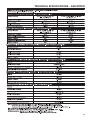
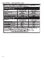
Technical Specications – Gas Dryer ................................ 21
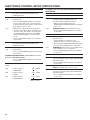
Electronic Control Setup Instructions ............................... 22
Warranty ............................................................................... 27
TABLE DES MATIÈRES
Page
Sécurité du sèche-linge ........................................................ 28
Élimination du sèche-linge ................................................... 31
Outils et pièces ..................................................................... 32
Dimensions/Distances de dégagement ............................. 33
Exigences d’installation ....................................................... 34
Exigences concernant l’évacuation .................................... 37
Spécications de l’alimentation en gaz ............................. 40
Installation des pieds de nivellement, du dispositif
de paiement et de la caisse à monnaie ............................... 41
Nivellement ........................................................................... 42
Achever l’installation ............................................................ 43
Inversion du sens d’ouverture de la porte (facultatif) ........ 44
Instructions d’entretien ........................................................ 46
Si vous avez besoin d’assistance ....................................... 46
Fiche technique – sèche-linge à gaz .................................. 47
Instructions de réglage du tableau
de commande électronique ................................................. 48
Garantie ................................................................................. 54
ÍNDICE
Página
Seguridad de la secadora ..................................................... 55
Eliminación de la secadora .................................................. 58
Herramientas y piezas .......................................................... 59
Dimensiones y espacios libres ............................................ 60
Requisitos de instalación ..................................................... 61
Requisitos de ventilación ..................................................... 64
Requisitos del suministro de gas ........................................ 67
Instalación de las patas, del dispositivo del pago
y la caja de monedas ............................................................ 68
Nivelación .............................................................................. 69
Complete la instalación ....................................................... 70
Cómo invertir el cierre de la puerta (opcional) .................. 71
Instrucciones de mantenimiento ......................................... 73
Si necesita ayuda ................................................................. 73
Especicaciones técnicas – secadora a gas ..................... 74
Instrucciones de programación
del control electrónico ......................................................... 75
Garantía ................................................................................. 81
INDICE
Pagina
Sicurezza dell’asciugatrice .................................................. 82
Eliminazione dell’asciugatrice ............................................. 85
Attrezzi e componenti ......................................................... 86
Dimensioni/spazi ................................................................. 87
Requisiti dell’installazione .................................................. 88
Requisiti di scarico .............................................................. 91
Requisiti di alimentazione del gas ..................................... 93
Installazione dei piedini di regolazione, dello
dispositivo di pagamento e del salvadanaio ..................... 94
Livellamento ......................................................................... 95
Completamento dell’installazione ..................................... 96
Inversione della rotazione di apertura (facoltativo) .......... 97
Istruzioni di manutenzione .................................................. 99
Se avete bisogno dell’assistenza ....................................... 99
Dati tecnici – asciugatrice a gas ...................................... 100
Congurazione dei controlli elettronici ........................... 101
Garanzia ............................................................................. 107

3
DRYER SAFETY
The dryer shall be disconnected from its power source during service and when replacing parts. If the removal of plug is
foreseen, it shall be clearly indicated that the removal of the plug has to be such that an operator can check from any of the
points to which they have access that the plug remains removed.
If this is not possible, due to the construction of the dryer or its installation, a disconnection with a locking system in the
isolated position shall be provided.
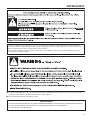
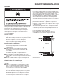
n It is recommended that the owner post, in a prominent location, instructions for the customer’s use in the event the customer
smells gas. This information should be obtained from your gas supplier.
n Post the following warning in a prominent location.
FOR YOUR SAFETY
1. DO NOT USE OR STORE PETROL OR OTHER FLAMMABLE MATERIALS IN THIS APPLIANCE OR NEAR THIS APPLIANCE.
2. DO NOT SPRAY AEROSOLS IN THE VICINITY OF THIS APPLIANCE WHILE IT IS IN OPERATION.
3. DO NOT MODIFY THIS APPLIANCE.

4
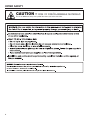
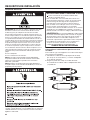
DRYER SAFETY
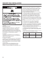
CAUTION –
RISK OF FIRE/FLAMMABLE MATERIALS
This is an additional safety alert symbol that alerts you to the risk of re.

5
DRYER SAFETY
n Do not install or store the dryer where it will be exposed
to the weather.
n Do not tamper with controls.
n Clean dryer lint screen before or after each load.
n Do not use this dryer without the lint screen in place.
n Do not repair or replace any part of the dryer or attempt
any servicing unless specically recommended in
this Use and Care Guide or in published user-repair
instructions that you understand and have the skills
to carry out.
n Do not use fabric softeners or products to eliminate static
unless recommended by the manufacturer of the fabric
softener or product.
n Do not use heat to dry articles containing foam rubber
or similarly textured rubber-like materials.
n The nal part of a tumble dryer cycle occurs without
heat (cool-down cycle) to ensure that the articles are left
at a temperature that ensures that the items will not be
damaged.
n WARNING: Never stop a tumble dryer before the end
of the drying cycle unless all items are quickly removed
and spread out so that the heat is dissipated. (Avoids risk
of spontaneous combustion).
n In case of electrical supply failure, remove the load
quickly and spread it out to avoid risk of spontaneous
combustion.
n Keep area around the exhaust opening and adjacent
surrounding areas free from the accumulation of lint,
dust, and dirt.
n The fresh air ventilation openings into the room and into
the dryer must not be blocked or sealed.
n Emergency stop control: After installation, access to
mains plug or disconnection from mains supply via a
double-pole switch must be ensured at all times in order
to ensure immediate deactivation of the dryer in case of
emergency.
n The interior of the dryer and dryer exhaust vent should
be cleaned periodically by qualied service personnel.
n See “Electrical Requirements” section for earthing
instructions.
n The dryer shall be disconnected from its power source
during service and when replacing parts. If the removal
of the plug is foreseen, it shall be clearly indicated that it
be possible for the operator to conrm the removal of the
plug from any point of access.
If this is not possible due to the construction of the dryer
or its installation, a disconnection with a locking system
in the isolated position shall be provided.
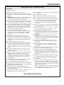
IMPORTANT SAFETY INSTRUCTIONS
WARNING: To reduce the risk of re, electric shock, or injury to persons when using the dryer, follow basic precautions,
including the following:
SAVE THESE INSTRUCTIONS
n Read all instructions before using the dryer.
n This dryer is intended only for drying clothes and textiles
that have been washed in water. Do not use for any other
purpose.
n WARNING: If you smell gas, do not use the dryer or any
electrical equipment nearby. Warn other people to clear
the area. Contact the dryer owner immediately.
n Do not place items exposed to cooking oils in your dryer.
Items contaminated with cooking oils may contribute to
a chemical reaction that could cause a load to catch re.
n If it is unavoidable that fabrics that contain vegetable or
cooking oil or that have been contaminated by hair care
products be placed in a tumble dryer, they should rst
be washed in hot water with extra detergent – this will
reduce, but not eliminate the hazard.
n Do not dry articles that have been previously
cleaned in, washed in, soaked in, or spotted with petrol,
dry-cleaning solvents, other ammable, or explosive
substances as they give off vapors that could ignite
or explode.
n Items that have been soiled with substances such
as acetone, alcohol, petrol, kerosene, spot removers,
turpentine, waxes, and wax removers should be washed
in hot water with extra detergent before being dried in
the dryer.
n Do not dry unwashed items in the dryer.
n Do not use this dryer if industrial chemicals have been
used for cleaning. The possible presence of residual
quantities of aggressive or decomposed chemicals in
the load may produce damage to the dryer and harmful
fumes.
n Do not allow children to play on or in the dryer. Close
supervision of children is necessary when the dryer is
used near children.
n This dryer is not intended for use by persons (including
children) with reduced physical, sensory, or mental
capabilities, or lack of experience or knowledge,
unless they have been given supervision or instruction
concerning use of the dryer by a person responsible
for their safety.
n Before the dryer is removed from service or discarded,
remove the door to the dryer compartment.
n Do not reach into the dryer if the drum is moving.
n Opening the dryer door will stop the function of the dryer.
n When loading or re-loading the dryer, avoid touching hot
metal parts of the drum (burn risk).
n If drum rotation is blocked due to trapped textiles,
disconnect the dryer from the electrical supply before gently
removing the blockage.
n If the dryer is not heating, or appears to be defective or
damaged, do not use it. Contact the owner.

6
DRYER DISPOSAL
This appliance is marked according to the European directive 2012/19/EU on Waste Electrical and Electronic Equipment
(WEEE).
By ensuring this product is disposed of correctly, you will help avoid potential negative consequences for the environment
and human health, which could otherwise be caused by inappropriate waste handling of this product.
The symbol on the product, or on the documents accompanying the product, indicates that this appliance may not be
treated as household waste. Instead it shall be handed over to the applicable collection point for the recycling of electrical
and electronic equipment.
Disposal must be carried out in accordance with local environmental regulations for waste disposal.
For more detailed information about treatment, recovery and recycling of this product, please contact your local city ofce,
your household waste disposal service or the shop where you purchased the product.
MODEL NOMENCLATURE:
MDG – Maytag Dryer – Gas PN – Electronic Control – Non-Pay
## (e.g. 28) – Model Type Number PD – Electronic Control – Coin Drop Enabled

7
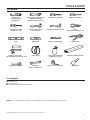
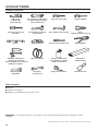
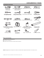
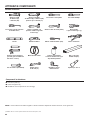
Tools Needed:
203 mm (8") 203 mm (8") or 254 mm (10") Flat-blade screwdriver Phillips screwdriver
or 254 mm (10") Adjustable wrench
Pipe wrench that opens to 25 mm (1")
Torx T20
®†
Security 25 mm (1") Hex-head 8 mm (5/16") Socket wrench Pliers
screwdriver or bit socket wrench (that open to 39 mm [1
9
/
16
"])
Level Utility knife 6 mm (1/4") Nut driver Locking pliers
Caulk gun and caulk Vent clamps Pipe-joint compound 686 mm (27") Wood block
(for installing new exhaust vent) suitable for gas type
Flashlight (optional) 25 mm (1") Ruler or measuring tape Putty knife
Open-end wrenches
TOOLS & PARTS
†® TORX and T20 are registered trademarks of Acument Intellectual Properties, LLC.
NOTE: The circuit diagram for this dryer is located inside the lower front panel, within the Tech Sheets.
Parts Supplied:
n Foot boots (4)
n Leveling legs (4)
n PN models: Card reader bezel, hardware

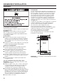
8
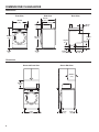
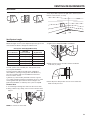
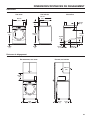
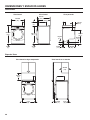
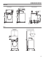
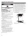
DIMENSIONS/CLEARANCES
Front View Side View Back View
Dimensions
Clearances
Recessed Front View
686 mm
(27")
965 mm
(38")
25 mm
(
1"
)
736 mm
(29")
921 mm
(36
1
/4")
25 mm
(
1"
)
695 mm
(27
1
/4")
203 mm
(8")
356 mm
(14")
25 mm
(1")
0 mm
(0")
381 mm
(15")
0 mm
(0")
159 mm
(6
1
/4")
715 mm
(28
1
/8")
89 mm
(3
1
/2")
358 mm
(
14"
)
32 mm
(
1
1
/4"
)
152 mm
(5
7
/8")
Closet Side View

9
Your dryer can be installed in a basement, laundry room,
or recessed area.
Companion appliance location requirements should also
be considered.
IMPORTANT: Do not install or store the dryer where it
will be exposed to the weather. Proper installation is your
responsibility.
You will need:
n A level oor with a maximum slope of 25 mm (1") under
entire dryer. Installing the dryer on soft oor surfaces,
such as carpets or surfaces with foam backing, is not
recommended.
n A sturdy and solid oor to support the dryer with a total
weight (load) of 204 kg (450 lbs).
Installation clearances
n The location must be large enough to allow the dryer door
to be fully opened.
n Additional spacing should be considered for ease of
installation and servicing. The door opens more than 180°.
n Additional clearances might be required for wall, door,
and oor moldings.
n Additional spacing of 25 mm (1") on all sides of the dryer
is recommended to reduce noise transfer.
n Companion appliance spacing should also be considered.
When installing a gas dryer:
IMPORTANT: Observe all governing codes and ordinances.
n Check code requirements: Some codes limit or do not
permit installation of clothes dryers in garages, closets,
or sleeping quarters. Contact your local building inspector.
NOTE: For installation in Australia and New Zealand,
install dryer in accordance with AS/NZS 5601.1 and local
governance codes.
n Make sure that lower edges of the cabinet, plus the back and
bottom sides of the dryer, are free of obstructions to permit
adequate clearance of air openings for combustion air. See
“Recessed Area and Closet Installation Instructions” below
for minimum spacing requirements.
n Do not install on carpet.
Location
INSTALLATION REQUIREMENTS
Recessed Area and Closet Installation Instructions
This dryer may be installed in a recessed area or closet. The
dryer must not be installed behind a lockable door, a sliding door,
or a door with a hinge on the opposite side to that of the dryer
in such a way that a full opening of the dryer door is restricted.
For recessed area and closet installations, minimum clearances
can be found on the warning label on the rear of the dryer or in
“Dimensions/Clearances.”
The installation spacing is in millimeters and is the minimum
allowable. Additional spacing should be considered for ease
of installation, servicing, and compliance with local codes
and ordinances.
If closet door is installed, the minimum unobstructed air
opening in the top and bottom is required. Louvered doors
with equivalent air openings are acceptable.
The dryer must be exhausted outdoors.
No other fuel-burning appliance may be installed in the same
closet as the dryer.
NOTE: For installation in Australia and New Zealand, refer
to AS/NZS 5601.1 for ventilation requirements.
NOTE: This dryer is not intended to be placed on top
of a washer.

10
INSTALLATION REQUIREMENTS
Electrical Requirements
EARTHING INSTRUCTIONS
SAVE THESE INSTRUCTIONS
IMPORTANT: Observe all governing codes and ordinances.
You will need an earthed electrical outlet located within
610 mm (2 feet) of either side of the dryer.
This dryer is supplied/tted with an electrical supply cord
and plug. It should be connected to electrical supply socket
at the voltage shown on the rating plate. The minimum supply
fuse capacity should be 5A. The dryer must be positioned so
that the plug is clearly visible and accessible. This plug also
provides the function of an emergency stop control for the user.
If the tted plug is not used, the electrical connection must be
carried out by a competent electrician in accordance with local
or national codes.
If the supply cord is damaged, it must be replaced with a
specially terminated cord by an authorized service agent
or a similarly competent person in order to avoid a hazard.
Do not use an adapter.
Do not use an extension cord.
NOTE: In accordance with the European EMC Directive
(2004/108/EC), the maximum electricity supply system
impedance to which the gas dryer should be connected
is declared to be 0.054 Ohm + j0.034 Ohm.
NOTE: Electrical safety standards: The manufacturer has
chosen compliance with IEC/EN.60335 standards as the most
appropriate for this product.
If codes permit and an additional earth bond wire is used, it is
recommended that a qualied electrician determine that the
earth bond path is adequate.
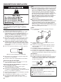
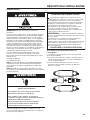
Using the universal cord included with this dryer:
The gas dryer is equipped with a universal cord with
interchangeable plugs.
1. To use the universal cord, select the plug end that ts your
electrical outlet, and plug it into the adapter on the supply
cord.
2. Secure the plug end in place on the cord by aligning the
2 cover halves over the cord adapter and clipping them
together.

11
INSTALLATION REQUIREMENTS
Gas Supply Requirements
IMPORTANT: Observe all governing codes and ordinances.
Gas Supply
Before installation, check that the local gas distribution
conditions, nature of gas and pressure, and the adjustment
of the appliance are compatible. Burner information will be
found on the model/serial rating plate in the door recess of the
dryer. If this information does not agree with the type of gas
available, see your dealer.
Natural Gas:
This dryer is factory adjusted for use with NATURAL GAS (G20),
and no further adjustment should be required at installation.
L.P. Gas:
This dryer is also certied for use with L.P. (propane or butane)
gases with appropriate conversion. No attempt shall be made
to convert the appliance from the gas specied on the model/
serial rating plate for use with a different gas without consulting
the serving gas supplier.
Conversion must be done by a competent service technician.
Gas conversion kit (European Country), part number
W10233219, is available for purchase from your dealer. Gas
conversion kit (Australia), part number W10315369, is available
for purchase from your dealer. Full instructions are supplied
with the kit.
Natural gas (France/Belgium):
This dryer is also certied for France/Belgium for use
with G20/G25 gases (20 mbar/25 mbar) with appropriate
conversion. No attempt should be made to convert this
appliance from the gas specied on the gas rating label
for use with a different gas without consulting the serving
gas supplier. Gas conversion must be done by a qualied gas
service technician. Conversion kit, part number (W10181947)
is available for purchase from your dealer. Full instructions are
supplied with the kit.
Supply line requirements:
Provide a rigid gas supply line to the dryer location. It should
be minimum 12.5 mm (1/2") ID. When acceptable to the gas
supplier and local codes, 10 mm (3/8") ID rigid supply line may
be used for lengths under 6.1 m (20'). Pipe-joint compounds
resistant to the action of L.P. gas must be used.
NOTE: For installation in Australia and New Zealand, refer
to AS/NZS 5601 for pipe sizing details.
Gas connection to the dryer itself should be made by means
of a exible gas hose suitable for the appliance and gas
category in accordance with national installation regulations.
If in doubt, contact the gas supplier. It should be minimum
10 mm (3/8") ID.
A means of restraint should be used between the dryer and the
wall to avoid straining of the rigid gas supply when the dryer
is moved. An appropriate length of chain and a wall hook is
recommended.
The dryer gas inlet connection is a 3/8" NPT thread.
An adapter is supplied for conversion to standard ISO.228-1
thread (3/8" BSP).
Check for leaks by using an approved noncorrosive
leak-detection solution. Bubbles will show a leak. Correct any
leak found. A pressure measurement tapping is provided on the
gas valve within the dryer, accessible after removal of the lower
front panel.
The dryer must be disconnected from the gas supply piping
system during any pressure testing of that system.
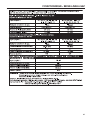
The expected pressures for the gas supply are listed in Inches
of Water Column in the table below:
Gas Supply Minimum Maximum
Natural Gas 5.2 10.5
LP Gas 8.0 13.0

12
VENTING REQUIREMENTS
WARNING: To reduce the risk of re, this dryer MUST BE
EXHAUSTED OUTDOORS.
IMPORTANT: Observe all governing codes and ordinances.
■ Following these venting requirements will minimize ducting
air noise.
■ Exhaust air must not be discharged into a ue which is used
for exhausting fumes from other appliances burning gas or
other fuels, including open res (i.e. available airow into
the room should match airow out from the room).
■ Adequate ventilation must be provided to avoid the back
ow of gases into the room from appliances burning other
fuels, including open res.
■ Dryer exhaust must not be connected into any gas vent,
chimney, wall, ceiling, attic, crawlspace, or a concealed
space of a building. Only rigid or exible metal vent shall
be used for exhausting.
■ Do not use an exhaust hood with a magnetic latch.
■ Only a 102 mm (4") heavy, metal exhaust vent and clamps
may be used.
■ Do not use plastic or metal foil vent.
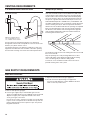
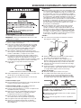
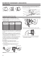
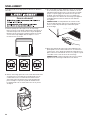
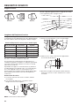
Rigid metal vent:
■ Recommended for best drying performance and to avoid
crushing and kinking.
Flexible metal vent: (Acceptable only if accessible to clean)
■ Must be fully extended and supported in nal dryer location.
■ Remove excess to avoid sagging and kinking that may
result in reduced airow and poor performance.
■ Do not install in enclosed walls, ceilings, or oors.
■ The total length should not exceed 2.4 m (7
3
⁄
4
ft.).
■ An exhaust hood should cap the vent to keep rodents
and insects from entering the building.
102 mm
(
4"
)
102 mm (4") heavy, metal exhaust vent
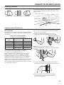
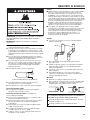
Elbows:
■ 45° elbows provide better airow than 90° elbows.
■ Plan installation to use the fewest number of elbows
and turns.
■ Allow as much room as possible when using elbows
or making turns. Bend vent gradually to avoid kinking.
■ Vent outlet is located at the center of the bottom dryer back.
■ The vent can be routed up, down, left, right, behind the
dryer, or straight out the back of the dryer.
Clamps:
■ Use clamps to seal all joints.
■ Exhaust vent must not be connected or secured with
screws or other fastening devices that extend into interior
of duct and catch lint. Do not use duct tape.
Better
Good
NOTES:
n Although usually each single-load dryer should have
an unobstructed outdoor air opening of 24 in.
2
(154 cm
2
)
(based on 1 in.
2
[6.5 cm
2
] per 1,000 Btu [252 kcal]), common
makeup air openings are also acceptable. Set up common
openings so the makeup air is distributed equally to all of
the dryers. Keep in mind that the coverage area must be
increased by 33% to account for the use of registers or
louvers over the openings. Also, makeup air openings
should not be installed near the location where exhaust
vents exit the building.
n If using an existing vent system, clean lint from entire length
of the system and make sure exhaust hood is not plugged
with lint. Replace plastic or metal foil vents with rigid metal
or exible metal vents. Review “Vent System Chart” and,
if necessary, modify existing vent system to achieve best
drying performance.

13
12" min.
(305 mm)
102 mm (4") Diameter Exhaust Hoods
Box hood Louvered hood Angled hood
Vent Hoods
VENTING REQUIREMENTS
Exhaust hood must be at least 305 mm (12") from the ground
or any object that may be in the path of the exhaust (such as
owers, rocks, bushes, or snow).
Maximum Vent Length/Vent Connection
Maximum length of vent system depends upon the type of vent
used, number of elbows, and type of exhaust hood.
Vent System Chart (Rigid Metal Vent)
No. of 90˚ Turns
Box and
Louvered Hood
Angled Hood
0 39.6 m (130 ft.) 39.3 m (129 ft.)
1 38.1 m (125 ft.) 36.3 m (119 ft.)
2 35.1 m (115 ft.) 33.2 m (109 ft.)
3 32.3 m (106 ft.) 30.5 m (100 ft.)
4 29.9 m (98 ft.) 28.0 m (92 ft.)
For vent systems not covered by the “Vent System Chart,”
see your parts distributor.
Provision must be made for enough air for combustion
and ventilation. (Check governing codes and ordinances.)
See “Recessed Area and Closet Installation Instructions”
in the “Location” section.
A 102 mm (4") outlet hood is preferred. However, a 64 mm
(2
1
⁄
2
") outlet exhaust hood may be used. A 64 mm (2
1
⁄
2
") outlet
creates greater back pressure than other hood types. For
permanent installation, a stationary vent system is required.
Connect Vent
1. If connecting to existing vent, make sure the vent is clean.
2. Using a 102 mm (4") clamp, connect vent to exhaust outlet
in dryer.
NOTE: Do not remove vent collar.
Vent System Length
3. Tighten hose clamp with Phillips screwdriver.
4. Make sure the vent is secured to exhaust hood with
a 102 mm (4") clamp.
5. Move dryer into nal position. Do not crush or kink vent.
Make sure dryer is level.
Vent collar
305 mm min.
(12")

14
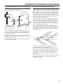
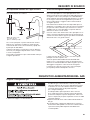
The outside end of main vent should have a sweep elbow
directed downward.
If main vent travels vertically through the roof, rather than
through wall, install a 180° sweep elbow on end of vent at least
610 mm (2 ft.) above surface of roof.
The opening in wall or roof shall have a diameter 13 mm (1⁄2")
larger than vent diameter. Vent should be centered in opening.
Do not install screening over end of vent for best performance.
A main vent can be used for venting a group of dryers. The
main vent should be sized to remove 5663 l/min. (200 CFM)
of air per dryer. Large-capacity lint screens of proper design
may be used in main vent if checked and cleaned frequently.
The room where the dryers are located should have make-up
air equal to or greater than CFM of all the dryers in the room.
A Back-draft Damper Kit is available from your distributor and
should be installed in the vent of each dryer to keep exhausted
air from returning into dryers and to keep exhaust in balance
within main vent. Unobstructed return air openings are required.
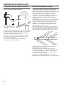
Each vent should enter the main vent at an angle pointing in
the direction of the airow. Vents entering from the opposite
side should be staggered to reduce the exhausted air from
interfering with the other vents.
The maximum angle of each vent entering the main vent should
be no more than 30°.
Keep air openings free of dry-cleaning uid fumes. Fumes
create acids which, when drawn through the dryer heating
units, can damage dryers and items being dried.
A clean-out cover should be located on the main vent for
periodic cleaning of the vent system.
If an Exhaust Hood Cannot Be Used Multiple Dryer Venting
VENTING REQUIREMENTS
30˚ max.
Air ow
* Minimum clearance above
any accumulation of snow,
ice, or debris such as leaves
1. Remove red cap from gas pipe.
2. Connect gas supply to dryer. If the exible gas hose has
10 mm (3/8") BSP thread, use the supplied conversion thread
adapter. Use pipe-joint compound resistant to the action
of L.P. gas for gas connections.
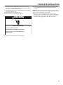
If necessary for service, open the toe panel. Use a putty knife
to press on the 2 toe panel locks located at the top of the toe
panel. Pull downward on the toe panel to open. Toe panel is
hinged at the bottom.
Make Gas Connection
GAS SUPPLY REQUIREMENTS
3. Open the shut-off valve in the gas supply line.
4. Test all connections by brushing on an approved
noncorrosive leak-detection solution. Bubbles will show
a leak. Correct any leaks found.

15
INSTALLING LEVELING LEGS, PAYMENT DEVICE, AND COIN BOX
The payment device, control panel lock and key, and coin box
lock and key are not included and are available from usual
industry sources.
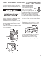
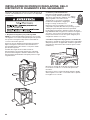
1. Prepare dryer for leveling legs
NOTE: Slide dryer onto cardboard or hardboard before moving
to avoid damaging oor covering.
Using two or more people, move dryer to desired installation
location.
Take tape off front corners of dryer. Open dryer and remove
the literature and parts packages. Wipe drum interior with damp
cloth to remove any dust.
Take two cardboard corners from the dryer carton and place
them on the oor in back of the dryer. Firmly grasp body of the
dryer and gently lay it on its back on the cardboard corners.
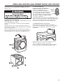
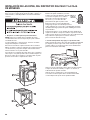
2. Screw in leveling legs
Examine leveling legs and nd diamond
marking. Screw legs into leg holes by
hand. Use an adjustable wrench or
25 mm (1") hex-head socket wrench to
nish turning legs until diamond marking
is no longer visible. Then t a covered foot
boot over each leg foot. A longer leveling foot
(Part Number 279810) is available if needed
on extremely sloped oors.
To protect the oor, use a large piece of cardboard from the
dryer carton. Stand dryer up on the cardboard. Slide the dryer
until it is close to its nal location. Leave enough room for
electrical connection and to connect the exhaust vent.
3. Install payment device and coin box
Remove the service door of the meter case by lifting
it up at the back. If applicable, install the money-accepting
device. (Refer to manufacturer’s instructions for proper
installation.)
Replace the meter case service door. Put the coin vault
with lock and key in the meter case opening.
Remove cardboard or hardboard from under dryer. Adjust
the legs of the dryer up or down until the dryer is level.
Foot
Diamond
marking

16
1. Remove cardboard from beneath dryer. Place a level on top
edges of dryer, checking each side and front. If not level, tip
dryer and adjust feet up or down as shown in Steps 3 and 4,
repeating as necessary.
LEVELING
Leveling your dryer properly reduces excess noise and vibration.
Not Level LEVEL Not Level
2. Grip dryer from top and rock back and forth, making sure all
four feet are rmly on oor. Repeat, rocking dryer from side
to side. If dryer rocks, go to Step 3 and adjust leveling feet.
If all four feet are in rm contact with oor, go to Step 4.
4. When dryer is level and all four feet are rmly in contact
with the oor, use a 25 mm or 1" open-end or adjustable
wrench to turn nuts on leveling feet tightly against dryer
cabinet.
HELPFUL TIP: You may want to prop dryer with wooden
block.
3. If dryer is not level, remove the rubber boot if used; then use
an adjustable wrench or 25 mm (1") hex-head socket wrench
to turn legs until adjustment is completed. Check levelness of
dryer after all feet are rmly touching the ground and the level
shows dryer top to be level front to back and side to side.
HELPFUL TIP: You may want to prop up front of dryer
about 102 mm (4") with a wood block or similar object
that will support weight of dryer.

17
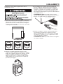
1. Check the electrical requirements. Be sure that you have
the correct electrical supply and the recommended earthing
method. See “Electrical Requirements.”
2. Check that all parts are now installed. If there is an extra part,
go back through the steps.
3. Check that you have all of your tools.
4. Dispose of/recycle all packaging materials.
5. Plug into an earthed outlet, or connect power.
COMPLETE INSTALLATION
6. Check dryer operation. Using a full heat cycle, let the dryer
run for at least ve minutes. Dryer will stop when time is
used up.
NOTE: Dryer door must be closed for dryer to operate. When
door is open, dryer stops, but timer continues to run. To restart
dryer, close door and press cycle keypad.
7. If the burner does not ignite and you can feel no heat
inside the dryer, shut off dryer for ve minutes. Check that
all supply valve controls are in “ON” position and that the
electrical cord is plugged in. Repeat ve-minute test.
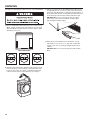
WARNING
Electric Shock Hazard
This dryer must be earthed.
Securely tighten all electrical connections.
Failure to do so can result in death, fire, or
electric shock.

18
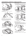
REVERSING DOOR SWING (OPTIONAL)
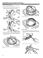
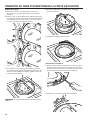
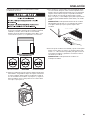
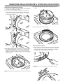
Remove the Door Assembly
1. Place a towel or soft cloth on top of dryer or work space
to avoid scratching of the surface.
2. Remove 3 of the 4 screws that hold the door hinge on the
front panel of the dryer. Partially loosen the remaining screw
with keyhole opening and lift the door off the screw.
3. Lay the door assembly on a previously prepared at surface
with the inside (inner door assembly) facing up, and remove
6 Phillips-head screws to release outer door assembly from
inner door assembly.
NOTE: It is important that you remove only 6 indicated screws.
4. Lift the inner door assembly off outer door assembly.
5. Rotate outer door 180°.
Reverse Hinge
1. Use a small at-blade screwdriver to remove 2 plug
strips from the inner door. Slide the head of the screwdriver
under the plugs, without scratching inner door surface, and
lift up strip.
2. Remove the 4 screws that attach to inner door hinge.

19
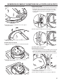
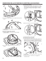
REVERSING DOOR SWING (OPTIONAL)
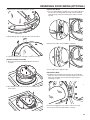
3. Move hinge to other side. Reinstall 4 screws.
4. Reinstall plug strips on opposite side of the inner door.
5. Check for ngerprints on the glass. Clean if necessary.
Replace the Door Assembly
1. Place the inner door assembly inside the outer door
assembly.
2. Reassemble the inner and outer door assemblies with
the 6 screws.
Reverse the Strike
1. Use a small at-blade screwdriver to remove plug strip from
the dryer door opening. Slide the head of the screwdriver
under the plugs, without scratching dryer surface, and lift
up strip.
2. Remove the strike using a Phillips screwdriver.
3. Insert strike on the opposite side.
Reinstall the Door
1. Partially insert the third screw from the top; then slide the
hinge onto this screw while hooking the hinge into the front
panel hole. Reattach door to dryer front panel with the
remaining 3 screws.
2. Check for ngerprints on the glass. Clean if necessary.
3. Close door and check that it latches securely.

20
MAINTENANCE INSTRUCTIONS
n Clean lint screen before and after each cycle.
n Removing accumulated lint:
From inside the dryer cabinet:
Lint should be removed every 2
years or more often, depending
on dryer usage. Cleaning should
be done by a qualied person.
From the exhaust vent:
Lint should be removed every 2
years, or more often, depending
on dryer usage.
n Keep area around dryer clear and free from combustible
materials, gasoline, and other ammable vapors and liquids.
n Keep dryer area clear and free from items that would
obstruct the ow of combustion and ventilation air.
If dryer does not operate, check the following:
n Electrical supply is connected.
n Circuit breaker is not tripped or house fuse is not blown.
n Door is closed. Listen closely to hear the door switch
activate.
n Cycle selection keypad has been pushed rmly and display
shows cycle time.
n Check that gas supply shut-off valves are set in open
position.
Direct all requests for service to the Maytag Commercial
Laundry Distributor that sold the appliance.
When calling, please know the purchase date and the
complete model and serial number of your appliance. This
information will help us to better respond to your request.
IF YOU NEED ASSISTANCE
La page est en cours de chargement...
La page est en cours de chargement...
La page est en cours de chargement...
La page est en cours de chargement...
La page est en cours de chargement...
La page est en cours de chargement...
La page est en cours de chargement...
La page est en cours de chargement...
La page est en cours de chargement...
La page est en cours de chargement...
La page est en cours de chargement...
La page est en cours de chargement...
La page est en cours de chargement...
La page est en cours de chargement...
La page est en cours de chargement...
La page est en cours de chargement...
La page est en cours de chargement...
La page est en cours de chargement...
La page est en cours de chargement...
La page est en cours de chargement...
La page est en cours de chargement...
La page est en cours de chargement...
La page est en cours de chargement...
La page est en cours de chargement...
La page est en cours de chargement...
La page est en cours de chargement...
La page est en cours de chargement...
La page est en cours de chargement...
La page est en cours de chargement...
La page est en cours de chargement...
La page est en cours de chargement...
La page est en cours de chargement...
La page est en cours de chargement...
La page est en cours de chargement...
La page est en cours de chargement...
La page est en cours de chargement...
La page est en cours de chargement...
La page est en cours de chargement...
La page est en cours de chargement...
La page est en cours de chargement...
La page est en cours de chargement...
La page est en cours de chargement...
La page est en cours de chargement...
La page est en cours de chargement...
La page est en cours de chargement...
La page est en cours de chargement...
La page est en cours de chargement...
La page est en cours de chargement...
La page est en cours de chargement...
La page est en cours de chargement...
La page est en cours de chargement...
La page est en cours de chargement...
La page est en cours de chargement...
La page est en cours de chargement...
La page est en cours de chargement...
La page est en cours de chargement...
La page est en cours de chargement...
La page est en cours de chargement...
La page est en cours de chargement...
La page est en cours de chargement...
La page est en cours de chargement...
La page est en cours de chargement...
La page est en cours de chargement...
La page est en cours de chargement...
La page est en cours de chargement...
La page est en cours de chargement...
La page est en cours de chargement...
La page est en cours de chargement...
La page est en cours de chargement...
La page est en cours de chargement...
La page est en cours de chargement...
La page est en cours de chargement...
La page est en cours de chargement...
La page est en cours de chargement...
La page est en cours de chargement...
La page est en cours de chargement...
La page est en cours de chargement...
La page est en cours de chargement...
La page est en cours de chargement...
La page est en cours de chargement...
La page est en cours de chargement...
La page est en cours de chargement...
La page est en cours de chargement...
La page est en cours de chargement...
La page est en cours de chargement...
La page est en cours de chargement...
La page est en cours de chargement...
La page est en cours de chargement...
-
 1
1
-
 2
2
-
 3
3
-
 4
4
-
 5
5
-
 6
6
-
 7
7
-
 8
8
-
 9
9
-
 10
10
-
 11
11
-
 12
12
-
 13
13
-
 14
14
-
 15
15
-
 16
16
-
 17
17
-
 18
18
-
 19
19
-
 20
20
-
 21
21
-
 22
22
-
 23
23
-
 24
24
-
 25
25
-
 26
26
-
 27
27
-
 28
28
-
 29
29
-
 30
30
-
 31
31
-
 32
32
-
 33
33
-
 34
34
-
 35
35
-
 36
36
-
 37
37
-
 38
38
-
 39
39
-
 40
40
-
 41
41
-
 42
42
-
 43
43
-
 44
44
-
 45
45
-
 46
46
-
 47
47
-
 48
48
-
 49
49
-
 50
50
-
 51
51
-
 52
52
-
 53
53
-
 54
54
-
 55
55
-
 56
56
-
 57
57
-
 58
58
-
 59
59
-
 60
60
-
 61
61
-
 62
62
-
 63
63
-
 64
64
-
 65
65
-
 66
66
-
 67
67
-
 68
68
-
 69
69
-
 70
70
-
 71
71
-
 72
72
-
 73
73
-
 74
74
-
 75
75
-
 76
76
-
 77
77
-
 78
78
-
 79
79
-
 80
80
-
 81
81
-
 82
82
-
 83
83
-
 84
84
-
 85
85
-
 86
86
-
 87
87
-
 88
88
-
 89
89
-
 90
90
-
 91
91
-
 92
92
-
 93
93
-
 94
94
-
 95
95
-
 96
96
-
 97
97
-
 98
98
-
 99
99
-
 100
100
-
 101
101
-
 102
102
-
 103
103
-
 104
104
-
 105
105
-
 106
106
-
 107
107
-
 108
108


Maytag MDG28PNCGW Installation Instructions Manual
- Catégorie
- Sèche-linge électriques
- Taper
- Installation Instructions Manual
dans d''autres langues
- italiano: Maytag MDG28PNCGW
- English: Maytag MDG28PNCGW
- español: Maytag MDG28PNCGW