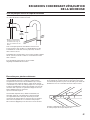
Maytag MHN33PDCGW Guide d'installation
- Catégorie
- Machines à laver
- Taper
- Guide d'installation

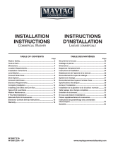
INSTALLATION
INSTRUCTIONS
CommerCial StaCked WaSher/
dryer GaS or eleCtriC
www.maytagcommerciallaundry.com
W10920979A
INSTRUCTIONS
D’INSTALLATION
laveuSe/SéCheuSe SuperpoSéeS
à uSaGe CommerCial
à Gaz ou éleCtrique
INSTRUCCIONES
DE INSTALACIÓN
lavadora/SeCadora ComerCialeS
apiladaS a GaS o eléCtriCaS
TABLE OF CONTENTS
Page
Stacked Washer/Dryer Safety .............. 2
Tools & Parts ............................................ 5
Alternate Parts and Accessories ......... 6
Dimensions/Clearances ....................... 7
Stacked Washer/Gas Dryer
Installation Requirements .................... 8
Stacked Washer/Electric Dryer
Installation Requirements .................. 11
Dryer Venting Requirements ............. 15
Dryer Gas Supply Requirements ...... 18
Installing Stacked Washer/Dryer ...... 19
Washer Drain System .......................... 22
Electric Dryer Electrical
Connections ........................................... 23
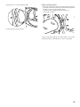
Leveling .................................................... 27
Reversing Dryer Door Swing .............. 29
Stacked Washer/Dryer
Maintenance Instructions ................... 32
If You Need Assistance ........................ 33
Electronic Control Setup
Instructions ............................................. 34
Warranty .................................................. 40
TABLE DES MATIÈRES
Page
Sécurité de la laveuse/sécheuse
superposées ............................................ 41
Outils et pièces ..................................... 44
Pièces supplémentaires
et accessoires ........................................ 45
Dimensions/Distances
de dégagement ..................................... 46
Exigences d’installation pour
la laveuse/sécheuse à gaz
superposées ............................................ 47
Exigences d’installation pour la
laveuse/sécheuse électriques
superposées .......................................... 50
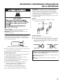
Exigences concernant
l’évacuation de la sécheuse .............. 55
Spécifications de l’alimentation
en gaz de la sécheuse ......................... 58
Installation de la laveuse/sécheuse
superposées ........................................... 59
Système d’évacuation
de la laveuse ........................................... 62
Raccordements de la sécheuse
électrique ................................................ 63
Nivellement .............................................. 67
Inversion du sens d’ouverture
de la porte de la sécheuse ..................69
Instructions d’entretien de la
laveuse/sécheuse superposées .......72
Si vous avez besoin d’assistance ..... 73
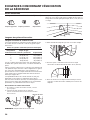
Instructions de réglage du tableau
de commande électronique ............... 74
Garantie ................................................... 81
ÍNDICE
Página
Seguridad de la lavadora/
secadora apiladas ................................. 82
Herramientas y piezas .......................... 85
Piezas y accesorios adicionales ...... 86
Dimensiones y espacios libres ......... 87
Requisitos de instalación de la
lavadora/secadora
a gas apiladas ........................................ 88
Requisitos de instalación de
la lavadora/secadora eléctricas
apiladas ................................................... 91
Requisitos de ventilación
de la secadora ....................................... 95
Requisitos del suministro
de gas de la secadora ......................... 98
Instalación de la lavadora/
secadora apiladas ................................. 99
Sistema de desagüe
de la lavadora ....................................... 102
Conexiones eléctricas
de la secadora eléctrica ................... 103
Nivelación ..............................................108
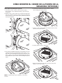
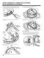
Cómo invertir el cierre
de la puerta de la secadora .............. 110
Instrucciones de mantenimiento
de la lavadora/secadora
apiladas .................................................. 112
Si necesita ayuda ................................ 113
Instrucciones de programación
del control electrónico ...................... 115
Garantía ................................................. 121

2
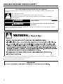
STACKED WASHER/DRYER SAFETY
You can be killed or seriously injured if you don't immediately
You
can be killed or seriously injured if you don't
follow
All safety messages will tell you what the potential hazard is, tell you how to reduce the chance of injury, and tell you what can
happen if the instructions are not followed.
Your safety and the safety of others are very important.
We have provided many important safety messages in this manual and on your appliance. Always read and obey all safety
messages.
This is the safety alert symbol.
This symbol alerts you to potential hazards that can kill or hurt you and others.
All safety messages will follow the safety alert symbol and either the word “DANGER” or “WARNING.”
These words mean:
follow instructions.
instructions.
DANGER
WARNING
■ It is recommended that the owner post, in a prominent location, instructions for the customer’s use in the event the customer smells
gas. This information should be obtained from your gas supplier.
■ Post the following warning in a prominent location.

3
STACKED WASHER/DRYER SAFETY
In the State of Massachusetts, the following installation instructions apply:
■ Installations and repairs must be performed by a qualified or licensed contractor, plumber, or gas fitter qualified or licensed by
the State of Massachusetts.
■ Acceptable Shut-off Devices: Gas Cocks and Ball Valves installed for use shall be listed.
■ A flexible gas connector, when used, must not exceed 4 feet (121.9 cm).
IMPORTANT: The gas installation must conform with local codes, or in the absence of local codes, with the National Fuel Gas
Code, ANSI Z223.1/NFPA 54, or the Natural Gas and Propane Installation Code, CSA B149.1.
The dryer must be electrically grounded in accordance with local codes, or in the absence of local codes, with the National
Electrical Code, ANSI/NFPA 70, or the Canadian Electrical Code, Part 1, CSA C22.1.
WARNING:
FIRE OR EXPLOSION HAZARD
Failure to follow safety warnings exactly could result in serious injury, death, or property
damage.
Do not store or use gasoline or other ammable vapors and liquids in the vicinity of this
or any other appliance.
–
–
WHAT TO DO IF YOU SMELL GAS:
•
Do not try to light any appliance.
•
Do not touch any electrical switch; do not use any phone in your building.
•
Immediately call your gas supplier from a neighbor’s phone. Follow the gas supplier’s
instructions.
•
If you cannot reach your gas supplier, call the re department.
–
Installation and service must be performed by a qualied installer, service agency, or
the gas supplier.
•
Clear the room, building, or area of all occupants.

4
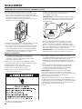
STACKED WASHER/DRYER SAFETY
IMPORTANT SAFETY INSTRUCTIONS
To reduce the risk of re, electric shock, or injury to persons when using the washer/dryer, follow basic
precautions, including the following:
WARNING:
SAVE THESE INSTRUCTIONS
■
Read all instructions before using the washer/dryer.
■
Do not place items exposed to cooking oils in your dryer.
Items contaminated with cooking oils may contribute to a
chemical reaction that could cause a load to catch re.
■
Do not wash or dry articles that have been previously
cleaned in, washed in, soaked in, or spotted with gasoline,
dry-cleaning solvents, other ammable, or explosive
substances as they give off vapors that could ignite or
explode.
■
Do not add gasoline, dry-cleaning solvents, or other
ammable, or explosive substances to the wash water.
These substances give off vapors that could ignite or
explode.
■
Do not allow children to play on or in the washer/dryer.
Close supervision of children is necessary when the
washer/dryer is used near children.
■
Before the washer/dryer is removed from service or
discarded, remove the doors to the washer/dryer
compartments.
■
Do not reach into the washer/dryer if the tub, agitator or
drum is moving.
■
Do not install or store the washer/dryer where it will be
exposed to water and/or the weather.
■
Do not tamper with controls.
■
Clean dryer lint screen before or after each load.
■
Under certain conditions, hydrogen gas may be produced
in a hot water system that has not been used for 2 weeks
or more. HYDROGEN GAS IS EXPLOSIVE. If the hot water
system has not been used for such a period, before using
the washing machine, turn on all hot water faucets and let
the water ow from each for several minutes. This will
release any accumulated hydrogen gas. As the gas is
ammable, do not smoke or use an open ame during
this time.
■
Do not repair or replace any part of the washer/dryer or
attempt any servicing unless specically recommended
in this Use and Care Guide or in published user-repair
instructions that you understand and have the skills to
carry out.
■
Do not use fabric softeners or products to eliminate static
unless recommended by the manufacturer of the fabric
softener or product.
■
Do not use heat to dry articles containing foam rubber or
similarly textured rubber-like materials.
■
Keep area around the exhaust opening and adjacent
surrounding areas free from the accumulation of lint, dust,
and dirt.
■
The interior of the machine and dryer exhaust vent should
be cleaned periodically by qualied service personnel.
■
See “Electrical Requirements” section of the Installation
Instructions booklet for grounding instructions.

5
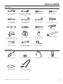
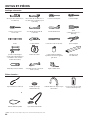
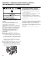
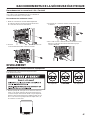
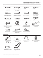
TOOLS & PARTS
Tools Needed:
8" (203 mm) or 10" (254 mm)
Pipe Wrench
8" (203 mm) or 10" (254 mm)
Adjustable Wrench That Opens
to 1" (25 mm)
Flat-Blade Screwdriver Phillips Screwdriver
Torx
®†
T-20 Security
Screwdriver or Bit
1" (25 mm) Hex-Head
Socket Wrench
5⁄16" Socket Wrench
Pliers
(that open to 1
9
/
16
" [39 mm])
Level
Utility Knife
1/4" (6 mm) Nut Driver
Locking Pliers
Caulk Gun and Caulk
(for installing new exhaust vent)
Vent Clamps
Pipe-Joint Compound
Suitable for Gas Type
27" (686 mm) Wood Block
Flashlight (optional)
1/2" (13 mm) and 9/16"
(14 mm) Open-End Wrenches
Ruler or Measuring Tape
Parts Supplied:
Water Inlet Hoses (2)
Inlet Hose Washers (4)
U-Shaped Hose Form
Transit Bolt Hole Plug (4)
Beaded Tie Strap
Drain Hose/Clamp
†
® TORX and T20 are registered trademarks of Acument Intellectual Properties, LLC.

6
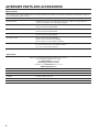
ALTERNATE PARTS AND ACCESSORIES
Alternate Parts
Your installation may require additional parts. If you are interested in purchasing one of the items listed here, call the toll-free number in
the “If You Need Assistance” section.
If You Have: You Will Need to Buy:
Overhead sewer Standard 20 gal. (76 L) 39" (990 mm) tall drain tub or utility sink, sump pump, and
connectors (available from local plumbing suppliers)
1" (25 mm) standpipe 2" (51 mm) diameter to 1" (25 mm) diameter Standpipe Adapter, Part Number 3363920
Connector Kit Part Number 285835
Drain hose too short Extension Drain Hose, Part Number 285863
Connector Kit Part Number 285835
Lint clogged Drain Drain Protector, Part Number 367031
Connector Kit Part Number 285835
Floor drain system Siphon break, Part Number 285834
Connector Kit (x2) Part Number 285835
Extension Drain Hose, Part Number 285863
Water faucets beyond reach of fill hoses Two longer water fill hoses:
6 ft. (1.8 m) 90° bend hose, Part Number 76314
10 ft. (3.0 m), Part Number 350008
Accessories
Enhance your washer/dryer with these premium accessories.
For more high-quality items or to order,
call 1-800-901-2042 or visit us at
www.maytag.com/accessories.
In Canada, call 1-800-807-6777 or visit us at
www.whirlpoolparts.ca
Part Number Accessory
8212526 Washer drip tray, fits under all
31682 All-purpose appliance cleaner
1903WH Laundry supply storage cart
279818 3-way dryer venting kit
285834 Siphon break kit

7
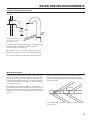
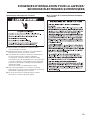
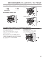
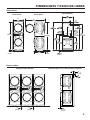
DIMENSIONS/CLEARANCES
Front View Side View Back View
27"
(686 mm)
1"
(25 mm)
74"
(1880 mm)
1"
(25 mm)
74"
(1880 mm)
51"
(1295 mm)
29.5 "
(751 mm)
1
/2
Clearances
Side Clearances Back/Top Clearances
0"
(0 mm)
0"
(0 mm)

8
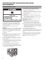
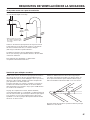
Selecting the proper location for your washer/dryer improves
performance and minimizes noise and possible washer “walk.”
Your washer/dryer can be installed in a basement, laundry room,
or recessed area. This washer/dryer is not intended for install in
a mobile home or recreational vehicle. See the “Drain System”
section for more information.
Companion appliance location requirements should also
be considered.
IMPORTANT: Do not install or store the washer/dryer where it will
be exposed to the weather. Do not store or operate the washer/dryer
in temperatures at or below 32°F (0°C). Some water can remain
in the washer and can cause damage in low temperatures. Proper
installation is your responsibility.
You will need:
■ A water heater set to deliver 120°F (49°C) water to the washer.
■ A grounded electrical outlet located within 6 ft. (1.8 m) of
where the power cord is attached to the back of the washer.
See the “Electrical Requirements” section.
■ Hot and cold water faucets located within 4 ft. (1.2 m) of the
hot and cold water fill valves, and water pressure of 20–100 psi
(137.9–689.6 kPa).
■ A level floor with a maximum slope of 1" (25 mm) under entire
washer/dryer. Installing the washer/dryer on soft floor surfaces,
such as carpets or surfaces with foam backing,
is not recommended.
■ A sturdy and solid floor to support the washer/dryer with
a total weight (water and load) of 450 lbs (204 kg).
■ A floor drain under the bulkhead. Prefabricated bulkheads with
electrical outlets, water inlet lines, and drain facilities should be
used only where local codes permit.
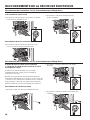
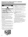
Stacked Washer/Gas Dryer Location
STACKED WASHER/GAS DRYER INSTALLATION
REQUIREMENTS
Stacked washer/gas dryer installation clearances:
■ The location must be large enough to allow the washer
and dryer doors to be fully opened.
■ Additional spacing should be considered for ease of installation
and servicing. The doors open more than 180°. The washer
door is not reversible.
■ Additional clearances might be required for wall, door, and
floor moldings.
■ Additional spacing of 1" (25 mm) on all sides of the washer/
dryer is recommended to reduce noise transfer and to improve
spin-up performance of the washer.
■ Companion appliance spacing should also be considered.
When installing a gas dryer:
IMPORTANT: Observe all governing codes and ordinances.
■ Check code requirements: Some codes limit or do not
permit installation of clothes dryers in garages, closets,
or sleeping quarters. Contact your local building inspector.
■ Make sure that lower edges of the cabinet, plus the back and
bottom sides of the washer, are free of obstructions to permit
adequate clearance of air openings for combustion air. See the
“Recessed Area and Closet Installation Instructions” below for
minimum spacing requirements.
Recessed Area Installation Instructions
This washer/dryer may be installed in a recessed area. For recessed
area installations, minimum clearances can be found on the warning
label on the rear of the dryer or in the “Dimensions/Clearances”
section.
The installation spacing is in inches and is the minimum allowable.
Additional spacing should be considered for ease of installation,
servicing, and compliance with local codes and ordinances.
NOTE: The dryer must be exhausted outdoors.

9
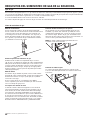
Stacked Washer/Gas Dryer Grounding
IMPORTANT: The washer/dryer must be electrically grounded in
accordance with local codes and ordinances or, in the absence
of local codes, with the National Electrical Code, ANSI/NFPA 70,
latest edition, or Canadian Electrical Code, CSA C22.1. If codes
permit and a separate ground wire is used, it is recommended that
a qualified electrical installer determine that the ground path
is adequate.
A copy of the above code standards can be obtained from:
National Fire Protection Association
One Batterymarch Park, Quincy, MA 02269
CSA International
8501 East Pleasant Valley Road
Cleveland, Ohio 44131-5575
■ Do not ground to a gas pipe.
■ Do not have a fuse in the neutral or ground circuit.
■ A 120 volt, 60 Hz, AC only, 15- or 20-amp, fused electrical
circuit is required. A time-delay fuse or circuit breaker is also
recommended. It is recommended that a separate circuit
serving only this washer/dryer be provided.
■ This washer/dryer is equipped with a power supply cord having
a 3 prong grounding plug.
■ To minimize the possibility of shock, the cord must be plugged
into a mating, 3 prong, grounding-type outlet, grounded in
accordance with local codes and ordinances. If a mating outlet
is not available, it is the personal responsibility and obligation of
the customer to have the properly grounded outlet installed by
a qualified electrician.
■ If codes permit and a separate ground wire is used, it is
recommended that a qualified electrician determine that the
ground path is adequate.
■ Check with a qualified electrician if you are not sure the
washer/dryer is properly grounded.
STACKED WASHER/GAS DRYER INSTALLATION
REQUIREMENTS
Stacked Washer/Gas Dryer Electrical Requirements

10
IMPORTANT: Observe all governing codes and ordinances.
This installation must conform with all local codes and ordinances.
In the absence of local codes, installation must conform with
American National Standard, National Fuel Gas Code ANSI
Z223.1/NFPA 54 or CAN/CSA B149.
A copy of the above code standards can be obtained from:
National Fire Protection Association
One Batterymarch Park, Quincy, MA 02269
CSA International
8501 East Pleasant Valley Road
Cleveland, Ohio 44131-5575
The design of this washer/dryer has been certified by CSA
International for use at altitudes up to 10,000 feet (3,048 m) above
sea level at the B.T.U. rating indicated on the model/serial plate.
Burner input adjustments are not required when the washer/dryer
is operated up to this elevation.
When installed above 10,000 feet (3,048 m), a four percent (4%)
reduction of the burner B.T.U. rating shown on the model/serial
plate is required for each 1,000 foot (305 m) increase in elevation.
For assistance when converting to other gas types and/or installing
above 10,000 feet (3,048 m) elevation, contact your local service
company.
WARNING
Explosion Hazard
Use a new CSA International approved gas supply line.
Install a shut-off valve.
Securely tighten all gas connections.
If connected to propane, have a qualified person make
sure gas pressure does not exceed 13" (33 cm) water
column.
Examples of a qualified person include:
licensed heating personnel,
authorized gas company personnel, and
authorized service personnel.
Failure to do so can result in death, explosion, or fire.
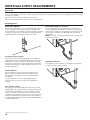
Stacked Washer/Gas Dryer Gas Supply
STACKED WASHER/GAS DRYER INSTALLATION
REQUIREMENTS

11
Selecting the proper location for your washer/dryer improves
performance and minimizes noise and possible washer “walk.”
Your washer/dryer can be installed in a basement, laundry room,
or recessed area. This washer/dryer is not intended for install in
a mobile home or recreational vehicle. See the “Drain System”
section.
Companion appliance location requirements should also be
considered.
IMPORTANT: Do not install or store the washer/dryer where it will
be exposed to the weather. Do not store or operate the washer/dryer
in temperatures at or below 32°F (0°C). Some water can remain
in the washer and can cause damage in low temperatures. Proper
installation is your responsibility.
You will need:
■ A water heater set to deliver 120°F (49°C) water to the washer.
■ A grounded electrical outlet located within 6 ft. (1.8 m) of
where the power cord is attached to the back of the washer.
See “Electrical Requirements.”
■ Hot and cold water faucets located within 4 ft. (1.2 m)
of the hot and cold water fill valves, and water pressure
of 20–100 psi (137.9–689.6 kPa).
■ A level floor with a maximum slope of 1" (25 mm) under entire
washer/dryer. Installing the washer/dryer on soft floor surfaces,
such as carpets or surfaces with foam backing,
is not recommended.
■ A sturdy and solid floor to support the washer/dryer with a total
weight (water and load) of 450 lbs (204 kg).
■ A floor drain under the bulkhead. Prefabricated bulkheads with
electrical outlets, water inlet lines, and drain facilities should be
used only where local codes permit.
Stacked Washer/Electric Dryer Location
STACKED WASHER/ELECTRIC DRYER INSTALLATION
REQUIREMENTS
Stacked washer/electric dryer installation clearances
■ The location must be large enough to allow the washer and
dryer doors to be fully opened.
■ Additional spacing should be considered for ease of installation
and servicing. The doors open more than 180°. The washer
door is not reversible.
■ Additional clearances might be required for wall, door, and floor
moldings.
■ Additional spacing of 1" (25 mm) on all sides of the washer/
dryer is recommended to reduce noise transfer, and improve
spin-up performance of washer.
■ Companion appliance spacing should also be considered.
Recessed Area and Closet Installation Instructions
This washer/dryer may be installed in a recessed area or closet.
For recessed area and closet installations, minimum clearances
can be found on the warning label on the rear of the dryer.
The installation spacing is in inches and is the minimum allowable.
Additional spacing should be considered for ease of installation,
servicing, and compliance with local codes and ordinances.
NOTE: The dryer must be exhausted outdoors.

12
■ Do not have a fuse in the neutral or ground circuit.
■ This washer/dryer is equipped with a power supply cord having
a 3 prong grounding plug.
■ To minimize the possibility of shock, the cord must be plugged
into a mating, 3 prong, grounding-type outlet, grounded in
accordance with local codes and ordinances. If a mating outlet
is not available, it is the personal responsibility and obligation of
the customer to have the properly grounded outlet installed by
a qualified electrician.
■ If codes permit and a separate ground wire is used, it is
recommended that a qualified electrician determine that
the ground path is adequate.
■ Check with a qualified electrician if you are not sure the washer
is properly grounded.
STACKED WASHER/ELECTRIC DRYER INSTALLATION
REQUIREMENTS
Stacked Washer/Electric Dryer Electrical Requirements
Stacked Washer/Electric Dryer Grounding
Washer Electrical Requirements

13
STACKED WASHER/ELECTRIC DRYER INSTALLATION
REQUIREMENTS
It is your responsibility:
■ To contact a qualified electrical installer.
■ To be sure that the electrical connection is adequate and in
conformance with the National Electrical Code, ANSI/NFPA
70-latest edition and all local codes and ordinances.
■ The National Electrical Code requires a 4-wire power supply
connection for homes built after 1996, dryer circuits involved in
remodeling after 1996, and all mobile home installations.
■ A copy of the above code standards can be obtained from:
National Fire Protection Association, One Batterymarch Park,
Quincy, MA 02269.
■ To supply the required 3- or 4-wire, single phase, 240 volt,
60 Hz., AC only electrical supply (or 3 or 4 wire, 120/208 volt
electrical supply, if specified on the serial/rating plate) on a
separate 30 amp circuit, fused on both sides of the line. A time
delay fuse or circuit breaker is recommended. Connect to an
individual branch circuit. Do not have a fuse in the neutral or
grounding circuit.
■ Do not use an extension cord.
■ If codes permit and a separate ground wire is used, it is
recommended that a qualified electrician determine that the
ground path is adequate.
Electrical Connection
To properly install your dryer, you must determine the type of
electrical connection you will be using and follow the instructions
provided for it here.
■ This dryer is manufactured ready to install with a 3-wire
electrical supply connection. The neutral ground conductor is
permanently connected to the neutral conductor (white wire)
within the dryer. If the dryer is installed with a 4-wire electrical
supply connection, the neutral ground conductor must be
removed from the external ground connector (green screw),
and secured under the neutral terminal (center or white wire)
of the terminal block. When the neutral ground conductor is
secured under the neutral terminal (center or white wire) of the
terminal block, the dryer cabinet is isolated from the neutral
conductor.
■ If local codes do not permit the connection of a neutral ground
wire to the neutral wire, see the “Optional 3-wire connection”
section.
■ A 4-wire power supply connection must be
used when the appliance is installed in a location where
grounding through the neutral conductor is prohibited.
Grounding through the neutral is prohibited for (1) new branch-
circuit installations, (2) mobile homes, (3) recreational vehicles,
and (4) areas where local codes prohibit grounding through the
neutral conductor.
Electric Dryer Power Supply Cord
If using a power supply cord:
Use a UL listed power supply cord kit marked for use with clothes
dryers. The kit should contain:
■ A UL listed 30 amp power supply cord, rated 240 volt
minimum. The cord should be type SRD or SRDT and be at
least 4 ft. (1.22 m) long. The wires that connect to the dryer
must end in ring terminals or “U” shaped spade terminals with
upturned ends.
■ A UL listed strain relief.
If your outlet looks like this:
4-wire
receptacle
(14-30R)
3-wire
receptacle
(10-30R)
Then choose a 4-wire power supply cord with ring or
spade terminals and UL listed strain relief. The 4-wire
power supply cord, at least 4 ft. (1.22 m) long, must
have four 10-gauge copper wires and match a 4-wire
receptacle of NEMA Type 14-30R. The ground wire
(ground conductor) may be either green or bare.
The neutral conductor must be identified by a white
cover.
Then choose a 3-wire power supply cord with ring or
spade terminals and UL listed strain relief. The 3-wire
power supply cord, at least 4 ft. (1.22 m) long, must
have three 10-gauge copper wires and match a
3-wire receptacle of NEMA Type 10-30R.
If your outlet looks like this:
Dryer Electrical Requirements

14
Fire Hazard
Use 10 gauge copper wire.
Use a UL listed strain relief.
Disconnect power before making electrical connections.
Connect neutral wire (white or center wire) to center
terminal.
Ground wire (green or bare wire) must be connected
to green ground connector.
Connect remaining 2 supply wires to remaining
2 terminals (gold).
Securely tighten all electrical connections.
Failure to do so can result in death, re, or
electrical shock.
Dryer Direct Wire
If connecting by direct wire:
Power supply cable must match power supply (4-wire or 3-wire)
and be:
■ Flexible armored cable or nonmetallic sheathed copper cable
(with ground wire), covered with flexible metallic conduit. All
current-carrying wires must be insulated.
■ 10-gauge solid copper wire (do not use aluminum).
■ At least 5 ft. (1.52 m) long.
STACKED WASHER/ELECTRIC DRYER INSTALLATION
REQUIREMENTS

15
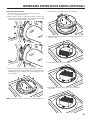
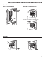
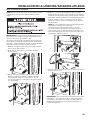
DRYER VENTING REQUIREMENTS
WARNING: To reduce the risk of fire, this dryer must be exhausted
outdoors.
IMPORTANT: Observe all governing codes and ordinances.
Dryer exhaust must not be connected into any gas vent, chimney,
wall, ceiling, attic, crawlspace, or a concealed space of a building.
Only rigid or flexible metal vent shall be used for exhausting.
■ Only a 4" (102 mm) heavy, metal exhaust vent and clamps may
be used.
■ Do not use plastic or metal foil vent.
Rigid metal vent:
■ Recommended for best drying performance and to avoid
crushing and kinking.
Flexible metal vent: (Acceptable only if accessible to clean)
■ Must be fully extended and supported in final dryer location.
■ Remove excess to avoid sagging and kinking that may result in
reduced airflow and poor performance.
■ Do not install in enclosed walls, ceilings, or floors.
■ The total length should not exceed 7
3
⁄
4
ft. (2.4 m).
NOTE: If using an existing vent system, clean lint from entire length
of the system and make sure exhaust hood is not plugged with lint.
Replace plastic or metal foil vents with rigid metal or flexible metal
vents. Review the “Vent System Chart” and if necessary, modify
existing vent system to achieve best drying performance.
4"
(102 mm)
4" (102 mm) heavy, metal exhaust vent
Elbows:
■ 45° elbows provide better airflow than 90° elbows.
Good
Better
Clamps:
■ Use clamps to seal all joints.
■ Exhaust vent must not be connected or secured with screws
or other fastening devices that extend into interior of duct and
catch lint. Do not use duct tape.

16
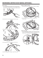
4" (102 mm) Diameter Exhaust Hoods
box hood louvered hood angled hood
Vent Hoods
DRYER VENTING REQUIREMENTS
Exhaust hood must be at least 12" (305 mm) from the ground or
any object that may be in the path of the exhaust (such as flowers,
rocks, bushes, or snow).
Maximum Vent Length/Vent Connection
Maximum length of vent system depends upon the type of vent
used, number of elbows, and type of exhaust hood.
Vent System Chart (Rigid Metal Vent)
No. of
90˚ Turns
Box and
Louvered Hoods
Angled
Hood
0 135 ft. (41.2 m) 129 ft. (39.3 m)
1 125 ft. (38.1 m) 119 ft. (36.3 m)
2 115 ft. (35.1 m) 109 ft. (33.2 m)
3 106 ft. (32.3 m) 100 ft. (30.5 m)
4 98 ft. (29.9 m) 92 ft. (28.0 m)
For vent systems not covered by the vent specification chart, see
your parts distributor.
Provision must be made for enough air for combustion and
ventilation. (Check governing codes and ordinances.) See the
“Recessed Area and Closet Installation Instructions” in the
“Stacked Washer/Gas Dryer Location” and “Stacked Washer/
Electric Dryer Location” sections.
A 4" (102 mm) outlet hood is preferred. However, a 2
1
⁄
2
" (64 mm)
outlet exhaust hood may be used. A 2
1
⁄
2
" (64 mm) outlet creates
greater back pressure than other hood types.
For permanent installation, a stationary vent system is required.
Connect Vent
1. If connecting to existing vent, make sure the vent is clean.
2. Using a 4" (102 mm) clamp, connect vent to exhaust outlet
in dryer.
NOTE: Do not remove vent collar.
Vent System Length
3. Tighten hose clamp with Phillips screwdriver.
4. Make sure the vent is secured to exhaust hood with
a 4" (102 mm) clamp.
5. Move dryer into final position. Do not crush or kink vent. Make
sure dryer is level.
12" min.
(305 mm)
Vent collar

17
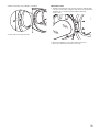
The outside end of main vent should have a sweep elbow directed
downward.
If main vent travels vertically through the roof, rather than through
wall, install a 180° sweep elbow on end of vent at least
2 ft. (610 mm) above surface of roof.
The opening in wall or roof shall have a diameter 1⁄2" (13 mm)
larger than vent diameter. Vent should be centered in opening.
Do not install screening over end of vent for best performance.
12" min.
(305 mm)*
A main vent can be used for venting a group of dryers. The main
vent should be sized to remove 200 CFM of air per dryer. Large-
capacity lint screens of proper design may be used in main vent
if checked and cleaned frequently. The room where the dryers are
located should have make-up air equal to or greater than CFM of
all the dryers in the room.
Back-draft Damper Kit, Part No. 3391910, is available from
your distributor and should be installed in the vent of each dryer to
keep exhausted air from returning into dryers and to keep exhaust
in balance within main vent. Unobstructed return air openings are
required.
If an Exhaust Hood Cannot be Used
Multiple Dryer Venting
DRYER VENTING REQUIREMENTS
Each vent should enter the main vent at an angle pointing in the
direction of the airflow. Vents entering from the opposite side
should be staggered to reduce the exhausted air from interfering
with the other vents.
The maximum angle of each vent entering the main vent should be
no more than 30°.
24" min.
(610 mm)
30˚ max.
Air ow
* Minimum clearance above any
accumulation of snow, ice, or
debris such as leaves

18
This dryer is equipped for use with natural gas. It is design-certified by CSA International for propane and butane gases with appropriate
conversion. No attempt shall be made to convert dryer from gas specified on serial/rating plate for use with a different gas without consulting
the serving gas supplier.
Conversion must be done by a qualified service technician.
Gas conversion kit part numbers are listed on gas valve burner base.
Type of Gas
DRYER GAS SUPPLY REQUIREMENTS
Recommended Method
Provide a gas supply line of 1⁄2" (13 mm) rigid (IPS) pipe to dryer
location. Pipe joint compounds that resist action of propane gas
must be used. Do not use TEFLON
®†
tape. With propage gas, piping
or tubing size can be 1⁄2" (13 mm) minimum. Usually, propane gas
suppliers determine size and materials used in the system.
Gas Supply Pressure Testing
A 1/8" (3 mm) NPT minimum plugged tapping, accessible for
gauge testing, must be installed immediately downstream of the
installed shut-off valve to the dryer (as shown above). The dryer
must be disconnected from the gas supply piping system during
any pressure testing of the system at test pressures in excess of
1/2" psig (352 kg/m
2
).
Alternate Method
The gas supply may also be connected using 3⁄8" (10 mm)
approved copper or aluminum tubing. If the total length of
the supply line is more than 20 ft. (6.1 m), larger tubing will
be required.
If using natural gas, do not use copper tubing. Pipe joint
compounds that resist action of type of gas supplied must
be used.
Shut-off valve required
The supply line must be equipped with a manual shut-off valve
installed within 6 ft. (1.8 m) of dryer in accordance with National
Fuel Gas Code, ANSI Z223.1. This valve should be located in
same room as dryer. It should be in a location that allows ease
of opening and closing. Do not block access to shut-off valve. In
Canada, an individual manual shut-off valve must be installed in
accordance with the B149 installation codes CAN/CGA B149.1
and CAN/CGA B149.2.
Gas Supply Line
Flexible Metal Appliance Connector
It is recommended that a new flexible stainless steel gas line,
design-certified by CSA International, be used for connecting the
dryer to the gas supply line. (The gas pipe which extends through
the lower rear of the dryer is provided with 3⁄8" (10 mm) male
pipe thread.)
NOTE: Do not kink or damage the flexible stainless steel gas line
when moving the door.
Rigid Pipe Connection
The rigid pipe connection requires a combination of pipe fittings
to obtain an in-line connection to dryer.
†®TEFLON is a registered trademark of Chemours.

19
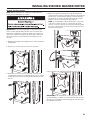
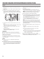
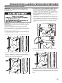
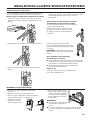
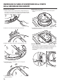
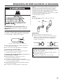
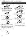
4. Models with separate washer power cords: Push the power
cord plug into the opening on the right side of the rear panel and
pull the power cord through the opening on the left side of the
rear panel and close holes with the attached cap. Do not pull
plug end of power cord through the right side hole.
NOTE: To avoid damage to internal washer parts or the power
cord, if the cord does not pull out of the washer rear panel
easily, do not force it. Remove the washer rear panel and guide
the power cord around the obstruction and out the hole on the
left side of the rear panel.
5. Close the bolt holes with the four transport bolt hole plugs.
IMPORTANT: If the washer/dryer is to be transported, call your
product distributor or installer. To avoid suspension and structural
damage, your washer/dryer must be properly set up for relocation
by a trained professional.
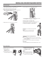
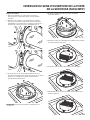
INSTALLING STACKED WASHER/DRYER
NOTE: Slide washer/dryer onto cardboard or hardboard before
moving to avoid damaging floor covering.
IMPORTANT: Position the washer/dryer so that the rear of the
washer is within approximately 3 ft. (900 mm) of its final location.
There are four shipping bolts in the rear panel of the washer that
support the suspension system during transportation. These bolts
also retain the power cord inside the washer until the bolts are
removed.
1. Keep the washer/dryer in the upright position while removing the
shipping bolts.
2. Using a 1/2" (13 mm) wrench, loosen each of the bolts.
3.
Once the bolt is loose, move it to the center of the hole and
completely pull out the bolt, including the plastic spacer covering
the bolt. Once all four bolts are removed, discard the bolts and
spacers.
Remove Transport System

20
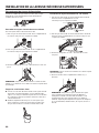
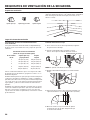
INSTALLING STACKED WASHER/DRYER
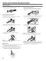
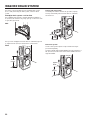
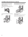
Insert new hose washers (supplied) into each end of the inlet
hoses. Firmly seat the washers in the couplings.
Connect Inlet Hoses to Water Faucets
Make sure the washer drum is empty.
1. Attach a hose to the hot water faucet. Screw on coupling
by hand until it is seated on the washer.
2. Attach a hose to the cold water faucet. Screw on coupling
by hand until it is seated on the washer.
3. Using pliers, tighten the couplings with an additional
two-thirds turn.
NOTE: Do not overtighten or use tape or sealants on the valve.
Damage to the valves can result.
Clear Water Lines
■ Run water through both faucets and inlet hoses, into a laundry
tub, drainpipe, or bucket, to get rid of particles
in the water lines that might clog the inlet valve screens.
■ Check the temperature of the water to make sure that the hot
water hose is connected to the hot water faucet and that the
cold water hose is connected to the cold water faucet.
coupling
washer
Connect Inlet Hoses to Washer
1. Attach the cold water hose to the washer’s cold water inlet
valve. Screw on coupling by hand until it is seated on the
washer.
2. Attach the hot water hose to the washer’s hot water inlet valve.
Screw on coupling by hand until it is seated on the washer.
3. Using pliers, tighten the couplings with an additional
two-thirds turn.
NOTE: Do not overtighten. Damage to the valve can result.
4. Turn on the water faucets completely and check for leaks.
NOTE: Replace inlet hoses after 5 years of use to reduce the risk
of hose failure. Record hose installation or replacement dates on
the hoses for future reference. Periodically inspect and replace
hoses if bulges, kinks, cuts, wear, or leaks are found.
Connect Inlet Hoses
La page est en cours de chargement...
La page est en cours de chargement...
La page est en cours de chargement...
La page est en cours de chargement...
La page est en cours de chargement...
La page est en cours de chargement...
La page est en cours de chargement...
La page est en cours de chargement...
La page est en cours de chargement...
La page est en cours de chargement...
La page est en cours de chargement...
La page est en cours de chargement...
La page est en cours de chargement...
La page est en cours de chargement...
La page est en cours de chargement...
La page est en cours de chargement...
La page est en cours de chargement...
La page est en cours de chargement...
La page est en cours de chargement...
La page est en cours de chargement...
La page est en cours de chargement...
La page est en cours de chargement...
La page est en cours de chargement...
La page est en cours de chargement...
La page est en cours de chargement...
La page est en cours de chargement...
La page est en cours de chargement...
La page est en cours de chargement...
La page est en cours de chargement...
La page est en cours de chargement...
La page est en cours de chargement...
La page est en cours de chargement...
La page est en cours de chargement...
La page est en cours de chargement...
La page est en cours de chargement...
La page est en cours de chargement...
La page est en cours de chargement...
La page est en cours de chargement...
La page est en cours de chargement...
La page est en cours de chargement...
La page est en cours de chargement...
La page est en cours de chargement...
La page est en cours de chargement...
La page est en cours de chargement...
La page est en cours de chargement...
La page est en cours de chargement...
La page est en cours de chargement...
La page est en cours de chargement...
La page est en cours de chargement...
La page est en cours de chargement...
La page est en cours de chargement...
La page est en cours de chargement...
La page est en cours de chargement...
La page est en cours de chargement...
La page est en cours de chargement...
La page est en cours de chargement...
La page est en cours de chargement...
La page est en cours de chargement...
La page est en cours de chargement...
La page est en cours de chargement...
La page est en cours de chargement...
La page est en cours de chargement...
La page est en cours de chargement...
La page est en cours de chargement...
La page est en cours de chargement...
La page est en cours de chargement...
La page est en cours de chargement...
La page est en cours de chargement...
La page est en cours de chargement...
La page est en cours de chargement...
La page est en cours de chargement...
La page est en cours de chargement...
La page est en cours de chargement...
La page est en cours de chargement...
La page est en cours de chargement...
La page est en cours de chargement...
La page est en cours de chargement...
La page est en cours de chargement...
La page est en cours de chargement...
La page est en cours de chargement...
La page est en cours de chargement...
La page est en cours de chargement...
La page est en cours de chargement...
La page est en cours de chargement...
La page est en cours de chargement...
La page est en cours de chargement...
La page est en cours de chargement...
La page est en cours de chargement...
La page est en cours de chargement...
La page est en cours de chargement...
La page est en cours de chargement...
La page est en cours de chargement...
La page est en cours de chargement...
La page est en cours de chargement...
La page est en cours de chargement...
La page est en cours de chargement...
La page est en cours de chargement...
La page est en cours de chargement...
La page est en cours de chargement...
La page est en cours de chargement...
La page est en cours de chargement...
La page est en cours de chargement...
La page est en cours de chargement...
La page est en cours de chargement...
-
 1
1
-
 2
2
-
 3
3
-
 4
4
-
 5
5
-
 6
6
-
 7
7
-
 8
8
-
 9
9
-
 10
10
-
 11
11
-
 12
12
-
 13
13
-
 14
14
-
 15
15
-
 16
16
-
 17
17
-
 18
18
-
 19
19
-
 20
20
-
 21
21
-
 22
22
-
 23
23
-
 24
24
-
 25
25
-
 26
26
-
 27
27
-
 28
28
-
 29
29
-
 30
30
-
 31
31
-
 32
32
-
 33
33
-
 34
34
-
 35
35
-
 36
36
-
 37
37
-
 38
38
-
 39
39
-
 40
40
-
 41
41
-
 42
42
-
 43
43
-
 44
44
-
 45
45
-
 46
46
-
 47
47
-
 48
48
-
 49
49
-
 50
50
-
 51
51
-
 52
52
-
 53
53
-
 54
54
-
 55
55
-
 56
56
-
 57
57
-
 58
58
-
 59
59
-
 60
60
-
 61
61
-
 62
62
-
 63
63
-
 64
64
-
 65
65
-
 66
66
-
 67
67
-
 68
68
-
 69
69
-
 70
70
-
 71
71
-
 72
72
-
 73
73
-
 74
74
-
 75
75
-
 76
76
-
 77
77
-
 78
78
-
 79
79
-
 80
80
-
 81
81
-
 82
82
-
 83
83
-
 84
84
-
 85
85
-
 86
86
-
 87
87
-
 88
88
-
 89
89
-
 90
90
-
 91
91
-
 92
92
-
 93
93
-
 94
94
-
 95
95
-
 96
96
-
 97
97
-
 98
98
-
 99
99
-
 100
100
-
 101
101
-
 102
102
-
 103
103
-
 104
104
-
 105
105
-
 106
106
-
 107
107
-
 108
108
-
 109
109
-
 110
110
-
 111
111
-
 112
112
-
 113
113
-
 114
114
-
 115
115
-
 116
116
-
 117
117
-
 118
118
-
 119
119
-
 120
120
-
 121
121
-
 122
122
-
 123
123
-
 124
124


Maytag MHN33PDCGW Guide d'installation
- Catégorie
- Machines à laver
- Taper
- Guide d'installation
dans d''autres langues
- English: Maytag MHN33PDCGW Installation guide
- español: Maytag MHN33PDCGW Guía de instalación
Documents connexes
Autres documents
-
Whirlpool WGT4027HW Guide d'installation
-
Whirlpool CET8000XQ0 Guide d'installation
-
Frigidaire FLCE7522AW Guide d'installation
-
Kenmore WET4124HW Guide d'installation
-
 Maytag Commercial MAT20MNAWW Guide d'installation
-
-
Jones Stephens S62304 Guide d'installation
