Maytag EPIC Z MGD9800TB0 Manuel utilisateur
- Catégorie
- Sèche-linge
- Taper
- Manuel utilisateur
Ce manuel convient également à

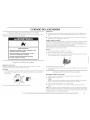
]VIAYI AG ®
E P IC _TM
FRONT-LOADING GAS DRYER
USE & CARE GUIDE
SECADORA A GAS DE CARGA FRONTAL
MANUAL DE USO Y CUIDADO
p % %
SECHEUSE A GAZ A CHARGEMENT FRONTAL
GUIDE D'UTILISATION ET D'ENTRETIEN
FOR QUESTIONS ABOUT FEA[URES, OPERATION/PERFORMANCE,
PARTS, ACCESSORIES OR SERVICE CALL: 1.800.688.9900
IN CANADA, CALl: 1.800.807.6777
VISIT OUR WEBSI1E AT WWW.MAYTAG.COM
IN CANADA, WWW.MAY I°AG.CA
SI IIENE PREGUN[AS RESPECTO A [AS CARACTER[STICAS,
FUNCIONAMIENTO, RENDIMIENTO, PARTES, ACCESORIOS O
SERVIC[O TECNICO, LI AME AL: 1.800.688.9900
EN CANAD,g,, El AME AL: 1.800.807.6777
VISITE NUESTRO SIT[O WEB EN
_/WW.MAYTAG .COM
EN CANAD,g,, WWW.MAYFAG.CA
AU CANADA, POUR ASSISTANCE, INSTALLA_1ION OU SERVICE,
COMPOSEZ I E : 1.800.807.6777
OU VISITEZ NOTRE SITE INTERNET ,_
WWW.MAYTAG .CA
W10139630A

_£:iiiiiiiiiiiiii@£!!@i!!!iiiiiii_ii_!!iiii[£_i_£_i_ _i:i!:_:_i!!iii!!i_ii_i!!_{_!i(!!_!_!_!_!!_iiiiiiiiiiiiiiiiiiiiiiiiiiii_i_i_¸¸
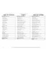
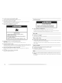
TABLE OF CONTENTS
DRYER SAFETY ...................................................................... 3
INSTALLATION INSTRUCTIONS ......................................... 5
Tools and Parts ................................................................... 5
Optional Pedestal ............................................................... 5
kocation Requirements ....................................................... 6
Electrical Requirements ...................................................... 8
Gas Supply Requirements .................................................. 9
Venting Requirements ...................................................... 10
Plan Vent System .............................................................. 12
Install Vent System ........................................................... 1_¢
Install keveling Eegs ......................................................... 1_
Make Gas Connection ...................................................... 14
Connect Vent ................................................................... 14
Level [Dryer ...................................................................... 14
Reverse Door Swing ......................................................... 15
Complete Installation ....................................................... 17
DRYER USE.......................................................................... 18
Starting Your Dryer ........................................................... 18
Stopping Your [Dryer ........................................................ 19
Pausing or Restarting ........................................................ 19
Control I.ocked ................................................................. 19
Drying and Cycle Tips ...................................................... 19
Status [.ights ...................................................................... 20
Cycles .............................................................................. 20
Additional Features .......................................................... 21
Drying Rack ..................................................................... 22
DRYER CARE ...................................................................... 23
Cleaning the Dryer ].ocation ............................................ 2_
Cleaning the Lint Screen .................................................. 23
Cleaning the Dryer Interior ............................................... 24
Removing Accumulated Lint ............................................ 24
Vacation and Moving Care .............................................. 24
Changing the Drum I.ight ................................................. 24
TROUBLESHOOTING ......................................................... 25
ASSISTANCE OR SERVICE ................................................... 27
WARRANTY ........................................................................ 28
P
INDICE
SEGURIDAD DE LA SECADORA ........................................ 30
INSTRUCCIONES DE INSTALACION ................................ 32
Herrarnientas y piezas ..................................................... 32
Pedestal optional ............................................................ 32
Requisitos de ubicaciGn ................................................... 33
Requisitos elGctricos ........................................................ 35
Requisitos del suministro de gas ...................................... 36
Requisitos de ventilaciGn ................................................. 37
PlanificaciGn del sistema de ventilaciGn .......................... 39
InstalaciGn del sistema de ventilaciGn ............................. 40
InstalaciGn de las patas niveladoras ................................. 41
ConexiGn del suministro de gas ....................................... 41
ConexiGn del ducto de escape ........................................ 42
NivelaciGn de la secadora ............................................... 42
CGmo invertir el cierre de la puerta ................................. 42
Complete la instalaciGn ................................................... 44
USO DE LA SECADORA ..................................................... 45
Puesta en marrha de la secadora ..................................... 45
Detenci6n de la marcha de la secadora .......................... 46
Pausa o reanudaci6n de la marcha .................................. 46
Control bloqueado .......................................................... 47
Sugerencias de ciclos y secado ........................................ 47
kuces de estado ............................................................... 47
Ciclos .............................................................................. 48
Caracter[sticas adicionales ............................................... 49
Estante de secado ............................................................ 50
CUIDADO DE LA SECADORA .......................................... 51
kimpieza del lugar donde est.1 la secadora ...................... 51
I impieza del filtro de pelusa ............................................ 51
I]mpieza del interior de la secadora ................................ 5I
EliminaciGn de pelusa acumulada ................................... 52
Cuidado para las vacaciones y la mudanza ..................... 52
Cambio de la luz del tambor ........................................... 52
SOLUCION DE PROBLEMAS ............................................. 53
AYUDA O SERVICIO TECNICO ......................................... 55
GARANTiA ......................................................................... 56
__!_i!!iiiiiiiiiiiiiiiiiiiiiiiiii!i!!@ii!!!!!!!!!!!!!!!!!ili!i!i!!ii!i!!:_ii[b 5ii!i£@iiii_ii!iiii!_£!iiiiiiiiiiiiiiiiiii_i_!ii!{iiiiiiill¸i_
TABLE DES MATIERES
SECURITI_ DE LA SECHEUSE ............................................... 57
INSTRUCTIONS D'INSTALLATION ................................... 59
Outillage et pi_ces ........................................................... 59
Pi_destal facultatif ............................................................ .-59
Exigences d'emplacement ................................................ 60
SpGcifications 61ectriques ................................................. 62
SpGcifications de I'alimentation en gaz ............................ 6_¢
Exigences concernant 1'Gvacuation .................................. 64
Planification du systGme d'Gvacuation ............................. 66
Installation du systGme d'Gvacuation ................................ 67
Installation des pieds de nivellement ............................... 67
Raccordement au gaz ...................................................... 68
Raccordement du conduit d'Gvacuation .......................... 69
Mise _ niveau de la s_cheuse ........................................... 69
Inversion du sens d'ouverture de la porte ........................ 69
Achever I'installation ....................................................... 71
UTILISATION DE LA SECHEUSE ........................................ 72
Mise en marche de la s6cheuse ....................................... 72
Arr6t de la s6cheuse ......................................................... 73
Pause ou remise en marche ............................................. 73
Verrouillage des commandes ........................................... 74
Conseils pour le s6chage et les programmes .................... 74
T@-noins lumineux ........................................................... 74
Programmes ..................................................................... 75
Caract6ristiques suppl6mentaires ..................................... 76
Grille de s6chage ............................................................. 77
ENTRETIEN DE LA SI_CHEUSE ........................................... 78
Nettoyage de I'emplacement de la s6cheuse ................... 78
Nettoyage du filtre _ charpie ............................................ 78
Nettoyage de I'int6rieur de la s6cheuse ............................ 79
Retrait de la charpie accumul6e ....................................... 79
Pr6cautions _ prendre pour les vacances et
avant un d6m6nagement .................................................. 79
Changement de I'ampoule d'6clairage du tambour ......... 79
DEPANNAGE ...................................................................... 80
ASSISTANCE OU SERVICE .................................................. 82
GARANTIE .......................................................................... 83
2 _l:lllllll_}_!!iii!iiii_ii!!iiiiiiiiiiiiii@%_ii}ii_ii}ii_ii}ii_ii}ii_ii}ii_ii}ii_ii}

i_i_!iii_i_iiIi!iiiiIi!iiiiIi!iiiiIi!iiiiii!iiiiii!iiiiii!iiiiii!iiiiii!iiiiii!iiiiii!iiiiii!iiiiii!iiiiii!iiiiii!iiiiii!iiiiii!iiiiii!iiiiii!iiiiii!iiiiii!iiiiii!iiiiii!iiiiii!iiiiii!iiiiii!iiiiii!iiiiii!iiiiii!iiiiii!iiiiii!iiiiii!iiiiii!iiiiii!iiiiii!iiiiii!iiiiii!iiiiii!iiiiii!iiiiii!iiiiii!iiiiii!iiiiii!iiiiii!iiiiii!iiiiii!iiiiii!iiiiii!iiiiii!iiiiii!iiiiii!iiiiii!iiiiii!iiiiii_)!_}iiiii!!_!_!_!_!_!_!_!_!_!_!_!_i_¸ _ii_ i!i!_iii_1i_i_i_i_i_i_i_i_i_i_i_i_i_i_i_i_i_i_i_i_i_i_i_i_i_i_i_i_i_i_i_i_i_i_i_i_i_i_i_i_i_i_i_i_i_i_i_i_i_i_i_i_i_i_i_i_i_i_i_i_i_i_i_i_i_i_i_i_i_i_i_i_i_i_i_i_i_i_i_i_i_i_i_i_i_i_i_i_i_i_i_i_i_i_i_i_i_i_i_i_i_i_i_i_i_i_i_i_i_i_i_i_i_i_i_i_i_i_i_i_i_i!!!_iiiiiiiiiiiiiiiiiiiiiiiiiiii_:_i!i
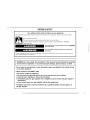
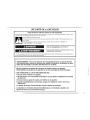
DRYER SAFETY
Your safety and the safety of others are very important.
We have provided many important safety messages in this manual and on your appliance. Always read and obey all safety
messages.
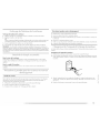
This is the safety alert symbol.
This symbol alerts you to potential hazards that can kill or hurt you and others.
All safety messages will follow the safety alert symbol and either the word "DANGER" or "WARNING."
These words mean:
You can be killed or seriously injured if you don't immediately
follow instructions.
You can be killed or seriously injured if you don't follow
instructions.
All safety messages will tell you what the potential hazard is, tell you how to reduce the chance of injury, and tell you what can
happen if the instructions are not followed.
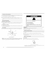
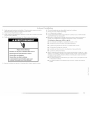
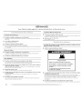
I WARNING: For your safety, the information in this manual must be followed to minimize
the risk of fire or explosion, or to prevent property damage, personal injury, or death,
- Do not store or use gasoline or other flammable vapors and liquids in the vicinity of this
or any other appliance.
- WHAT TO DO IF YOU SMELL GAS:
• Do not try to light any appliance.
• Do not touch any electrical switch; do not use any phone in your building.
• Clear the room, building, or area of all occupants.
• Immediately call your gas supplier from a neighbor's phone. Follow the gas supplier's
instructions.
• If you cannot reach your gas supplier, call the fire department.
- Installation and service must be performed by a qualified installer, service agency, or
the gas supplier.
.... :}

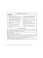
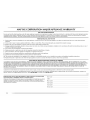
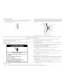
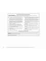
IMPORTANTSAFETYINSTRUCTIONS
WARNING: To reduce the risk of fire, electric shock, or injury to persons when using the dryer, follow basic precautions,
including the following:
[] Read all instructions before using the dryer.
[] Do not place items exposed to cooking oils in your dryer.
Items contaminated with cooking oils may contribute to
a chemical reaction that could cause a load to catch fire.
[] Do not dry articles that have been previously cleaned in,
washed in, soaked in, or spotted with gasoline, dry-
cleaning solvents, or other flammable or explosive
substances as they give off vapors that could ignite or
explode.
[] Do not allow children to play on or in the dryer. Close
supervision of children is necessary when the dryer is
used near children.
[] Before the dryer is removed from service or discarded,
remove the door to the drying compartment.
[] Do not reach into the dryer if the drum is moving.
[] Do not install or store the dryer where it will be exposed
to the weather.
[] Do not tamper with controls.
[] Do not repair or replace any part of the dryer or attempt
any servicing unless specifically recommended inthis
Use and Care Guide or in published user-repair
instructions that you understand and have the skills to
carry out.
[] Do not use fabric softeners or products to eliminate static
unless recommended by the manufacturer of the fabric
softener or product.
[] Do not use heat to dry articles containing foam rubber or
similarly textured rubber-like materials.
[] Clean lint screen before or after each load.
[] Keep area around the exhaust opening and adjacent
surrounding areas free from the accumulation of lint, dust,
and dirt.
[] The interior of the dryer and exhaust vent should be
cleaned periodically by qualified service personnel.
[] See installation instructions for grounding requirements.
SAVE THESE INSTRUCTIONS
In the State of Massachusetts, the following installation instructions apply:
[] Installations and repairs must be performed by a qualified or licensed contractor, plumber, or gasfitter qualified or licensed by
the State of Massachusetts.
[] If using a ball valve, it shall be a T-handle type.
[] A flexible gas connector, when used, must not exceed 3 feet.
iMPORTANT: The gas installation must conform with local codes, or in the absence of local codes, with the National Fuel Gas
Code, ANSI Z223.1/NFPA 54 or the Canadian Natural Gas and Propane Installation Code, CSA B149.1.
The dryer must be electrically grounded in accordance with local codes, or in the absence of local codes, with the National
Electrical Code, ANSI/NFPA 70 or Canadian Electrical Code, CSA C22.1.
4.

:ili;iiiiiiiiiiiiiiiiiiiiiiiiiiii!iiiiiiiiiIi!iiiiIi!iiiiIi!iiiiIi!iiiiii!iiiiii!iiiiii!iiiiii!iiiiii!iiiiii!iiiiii!iiiiii!iiiiii!iiiiii!iiiiii!iiiiii!iiiiii!iiiiii!iiiiii!iiiiii!iiiiii!iiiiii!iiiiii!iiiiii!iiiiii!iiiiii!iiiiii!iiiiii!iiiiii!iiiiii!iiiiii!iiiiii!iiiiii!iiiiii!iiiiii!iiiiii!iiiii_iii!i:iii!_!_!_!_!_i!!ii!_i!_!_!_!_!_i!i_ii!_i!ii!!_!_!_!_!!!g!!>:i_!;i_!!!ii:;>_!_i_!;i_!_i!!!!!!!!!_i_!ii!!!_i!!_!iiiii!_!:!_!!il!!!!!!!ii!_iiiiiii_i¸ !!_!_!_!_!_!_i!i_ii!_i!_ii!!_!_!_!_!_i!i_ii1!_!_!_!_!!_!Ii_i!ii_i_!!!iii!i:iii!!_i!!ii_iiii!!_!_i!i_ii!_i_!ii!ii!!_!_!!i!!:!ii_iiii_iXi_i_i_i!i!iiiii_i_i_i_i_i_i_i_i_i_i_i_i_i_i_i_i_i_i_i_i_i_i_i_i_i_i_i_i_i_i_i_i_i_i_i_i_i_i_i_i_i_i_i_i_i_i_i_i_i_i_i_i_i_i_i_i_i_i_i_i_i_i_i_i_i_i_i_i_i!!!iiiiiiiiiiiiiiiiiiiiiiiiiiiii_!i_¸i:
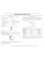
INSTALLATION INSTRUCTIONS
Gather fine required tools and parts before starting installation. Read and follow the
instructions provided with any tools listed here.
• 8" or 10" pipe wrench
• 8" or 10" adjustable wrench (for gas
connections)
• Flat-blade screwdriver
• Adjustable wrench that opens to 1" (2.5
cm) or hex-head socket wrench (for
adjusting dryer feet)
• V2'nut driver or socket wrench
(recommended)
• level
• Knife
• Vent clamps
• Pipe-joint compound resistant to I.P gas
• Caulking gun and compound (for
installing new exhaust vent)
• Pliers
• Tape measure
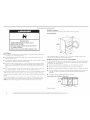
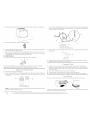
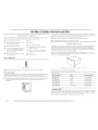
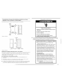
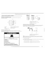
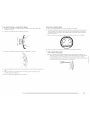
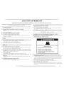
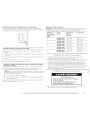
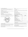
Are you placing the dryer on a pedestal? You have the option of purchasing pedestals of
different heights separately for this dryer. You may select a 10" (25.4 cm) pedestal or a
15.5" (39.4 cm) pedestal with a storage drawer. The pedestal will add to the total height of the
dryer for a total height of approximately 46" (116.8 cm) or 51.5" (1 "_;0.8cm), respectively.
For a garage installation, you will need to place the 10" (25.4 cm) pedestal at least
9" (22.9 cm) above the floor. You will need to place the 15.5' (?;9,4 cm) pedestal at least
3" (7,6 cm) above the floor.
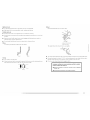
Parts supplied
Remove [)arts packages from dryer drum. Check that all parts are included.
4 [ewfling legs
NOTE: [::)o not use leveling legs if installing the dryer on a pedestal.
Parts needed
Check local codes and with gas supplier. Check existing gas supply, electrical supply and
venting. Read "Electrical Requirements," "Gas Supply Requirements" and "Venting
Requirements" before purchasing parts.
• For close-clearance installations between 31.5" (80.01 cm) and 37" (93.98 cm), see "Plan
Vent System" section for venting requirements.
(93.98 era)
Optional pedestal ( t5.5" 139.4 cm] model shown)
The pedestals are available in several colors.
lb order, call the dealer from whom you purchased your dryer or refer to the "Assistance or
Service" section.
Pedestal Height Color Part Number
10" (25.4 cm) White MHP1000SQ0
10" (25.4 cm) Black MHP1000SB0
15.5" (39.4 cm) White MHP1500SQ0
15.5" (39.4 cm) Black MHP1500SB0
15.5" (39.4 cm) Pacific Blue MHP1500SK0
Stack Kit
Are you planning to stack your washer and dryer? 1o do so, you will need to purchase a Stack
Kit. To order, call the dealer from whom you purchased your dryer or refer to the "Assistance
or Service" section. Ask for Part Number 8212640.
Mobile home installations require special parts (listed following) that may be ordered by
calling the dealer from whom you purchased your dryer. For further information, please refer
to the "Assistance or Service" section.
• Mobile Home Installation Kit. Ask for Part Number 346764.
• Metal exhaust system hardware.

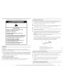
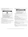
ExplosionHazard
Keep flammable materials and vapors, such as
gasoline, away from dryer,
Place dryer at least 18 inches (46 cm) above the floor
for a garage installation.
Failure to do so can result in death, e×plosion, or fire.
You will need
• A location that allows for proper exhaust installation. A gas dryer must be exhausted to
the outdoors. See "Venting Requirements."
• A grounded electrical outlet located within 2 ft (61 cm) of either side of the dryer. See
"Electrical Requirements."
• A sturdy floor to support the total dryer weight of 200 Ibs (90.7 kg). The combined weight
of a companion appliance should also be considered.
• A level floor with a maximum slope of 1" (2.5 cm) under entire dryer. If slope is greater
than 1" (2.5 cm), install Extended Dryer Feet Kit, Part Number 279810. Clothes may not
tumble properly, and automatic sensor cycles may not operate correctly if dryer is not
level.
• For a garage installation, you will need to place the dryer at least 18" (46 cm) above the
floon If using a pedestal, you will need 18" (46 cm) to the bottom of the dryer.
Do not operate your dryer at temperatures below 45°F (7°C). At lower temperatures, the dryer
might not shut off at the end of an automatic cycle. This can result in longer drying times.
The dryer must not be installed or stored in an area where it will be exposed to water and/or
weather.
Check code requirements. Some codes limit, or do not permit, installation of the dryer in
garages, closets, mobile homes or sleeping quarters. Contact your local building inspecton
NOTE: No other fuel-burning appliance can be installed in the same closet as a dryer.
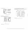
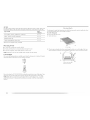
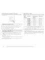
Installation clearances
[he location must be large enough to allow the dryer door to open fully.
Dryer Dimensions
(96.52 cm)
(80 cm) 27"
*Most installations require a minimum 5" (12.7 cm) clearance behind the dryer for the
exhaust vent with elbow. See "Venting Requirements."
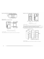
Installation spacing for recessed area or closet installation
[he following spacing dimensions are recommended for this dryer. This dryer has been tested
for spacing of 0" (0 cm) clearance on the sides and rear. Recommended spacing should be
considered for the following reasons:
• Additional spacing should be considered for ease of installation and servicing.
• Additional clearances might be required for wall, door and floor moldings.
• Additional spacing should be considered on all sides of the dryer to reduce noise transfer.
• For closet installation, with a door, minimum ventilation openings in the top and bottom
of the door are required. [ ouvered doors with equivalent ventilation openings are
acceptable.
• Companion appliance spacing should also be considered.
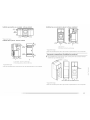
Custom undercounter installation - Dryer only
9" _ _IIW
(9cm) __ _ __ [Z]
38"rnin.
(96.52 cm)
I"* _ -_-..-.-27"---_ _ I"*
2.5 crn (68.6 cm) 2.5 cm
*Required spacing
6

Closet installation - Dryer only
_'_48 in.2_
(319 cm:
24in.2'
(188cmz) "
I1"'t* 81w_,-18"**1
(2.5cm) (8Ocm)(12.7cm)
A
_3"*
(7.6cm)
A. Side view - closet or confined area
B. Closet door with vents
*Required spacing
**For side or bottom venting, O" (0 cm) spacing is allowed.
Recessed or closet installation - Dryer on pedestal
oo
o
I -1''
(2.5 cm) (68.6 cm)
IiI
1".1I*- 31w.-_-Is"**l
(2.5 cm) (2.5 cm) (80 cm) (12.7 cm)
A B
Recommended installation spacing for cabinet installation
• For cabinet installation, with a door, minimum ventilation openings ill tile top of tile
cabinet are required,
" • _,_17.8 cm)
8"*
m) 5 ** 31_/2 11
(12.7cm)(80.0cm)(2.5cm)(2.5cm)(68.6cm)(2.5cm)
(22.9 cm)
* Required spacing
** For side or bottom venting, 0" (0 cm) spacing is allowed.
A. Recessed area
B.Side view - closet or confined are'a
*Required spacing
**For side or bottom venting, O" (0 cm) spacing is allowed.

Recommended installation spacing for recessed or closet installation, with
stacked washer and dryer
The dimensions shown are for the recommended spacing.
*Required spacing
48 irt. 2 *
(310crn2)
±
gNN-
T
o
24 in.2
(155cm2)
m
3"* (7.6 cm)
i
3"* (7.6 cm)
-_ _- 1"* (2.5crn)
(12.7crn)
6"* (_5.2 cm)
,>_,,
76" _........
(/93 cm) --
_ 1" --_ _ 27"_1_
(2.5 cm) 68.6 cm
*Required spacing
Mobile home - Additional installation requirements
This dryer is suitable for mobile home installations. The installation must conform to tile
Manufactured Home Construction and Safety Standard, Title 24 CFR, Part 3280 (formerly the
Federal Standard for Mobile Home Construction and Safety, Title 24, HUD Part 280) or
Standard CAN/CSA-Z240 MH.
Mobile home installations require:
[] Metal exhaust system hardware, which is aw_ilable for purchase from your dealer.
[] Mobile Home Installation Kit Part Number 346764. See "tools and Parts" section for
information on ordering.
[] Special provisions must be made in mobile homes to introduce outside air into the dryer.
[he opening (such as a nearby window) should be at least twice as large as the dryer
exhaust opening.
Electrical Shock Hazard
Plug into a grounded 3 prong outlet.
Do not remove ground prong.
Do not use an adapter.
Do not use an extension cord.
Failure to follow these instructions can result in death,
fire, or electrical shock.
120 Volt, 60 Hz., AC only, 15- or 20-amp fused electrical supply is required. A time-delay
fuse or circuit breaker is recommended, it is also recommended that a separate circuit
serving only this dryer be provided.
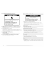
GROUNDING iNSTRUCTiONS
[] For a grounded, cord-connected dryer:
This dryer must be grounded. In the event of malfunction or
breakdown, grounding will reduce the risk of electric shock
by providing a path of least resistance for electric current.
This dryer is equipped with a cord having an equipment-
grounding conductor and a grounding plug. The plug must
be plugged into an appropriate outlet that is properly
installed and grounded in accordance with all local codes
and ordinances.
WARNING: Improper connection of the equipment-
grounding conductor can result in a risk of electric shock.
Check with a qualified electrician or service representative
or personnel if you are in doubt as to whether the dryer is
properly grounded. Do not modify the plug provided with the
dryer: if it will not fit the outlet, have a proper outlet installed
by a qualified electrician.
SAVE THESE INSTRUCTIONS
8

Explosion Hazard
Use a new CSA international approved gas supply line.
Install a shut=off valve.
Securely tighten all gas connections.
if connected to LP, have a qualified person make sure
gas pressure does not exceed 13" (33 cm) water
column.
Examples of a qualified person include:
licensed heating personnel,
authorized gas company personnel, and
authorized service personnel.
Failure to do so can result in death, explosion, or fire.
Gas Type
Natural gas:
This dryer is equipped for use with Natural gas. It is design-certified by CSA International for
[P/propane or butane/gases with appropriate conversion.
• Your dryer must have the correct burner for the type of gas in your home. Burner
information is located on the rating plate in the door well of your dryer. If this information
does not agree with the type of gas available, contact your dealer or call the phone
numbers referenced in the "Assistance or Service" section.
LP gas conversion:
Conversion must be made by a qualified technician.
No attempt shall be made to convert the appliance from the gas specified on the model/serial
rating plate for use with a different gas without consulting your gas company.
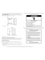
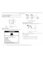
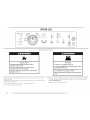
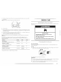
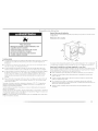
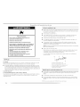
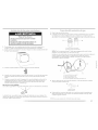
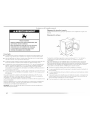
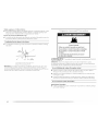
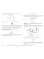
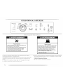
Gas supply line
• Must include Ws"NPT minimum plugged tapping accessible for test gauge connection,
immediately upstream of the gas connection to the dryer. See illustration.
• _/2"IPS pipe is recommended.
• %" approved aluminum or copper tubing is acceptable for lengths under 20 ft (6.1 m) if
local codes and gas supplier permit.
• If you are using Natural gas, do not use copper tubing.
• lengths over 20 ft (6.1 m) should use larger tubing and a different size adapter fitting.
• If your dryer has been converted to use [P gas, %" ].P compatible copper tubing can be
used. If the total length of the supply line is more than 20 ft (6.1 m), use larger pipe.
NOTE: Pipe-joint compounds that resist the action of I.P gas must be used. Do not use
[EF[.ON _'*tape.
• Must include a shutoff valve:
In the U.S.A.:
An individual manual shutoff valve must be installed within six (6) feet (1.8 m) of the dryer
in accordance with the National Fuel Gas Code, ANSI Z223.1. The location should be
easy to reach for opening and closing.
In Canada:
An individual manual shutoff valve must be installed in accordance with the Bq49.1,
Natural Gas and Propane Installation Code. [t is recommended that an individual manual
shutoff valve be installed within six (6) feet (1.8 m) of the dryer. The location should be
easy to reach for opening and closing.
A C E
i
B D
A. %" fl_'xible gas connector
B.%" pipe to flare"adapter fitting
C. Vs" NPT mil}imum plugged tapping
D. _/_"NPTgas supply line
E.Gas shutoff valve
t®TEFLON is a legistered trademark of E.I. DLI Pont De Nemouls and Company.
9

Gas supply connection requirements
• Use an elbow and a %" flare x %" NPT adapter fitting between the flexible gas connector
and the dryer gas pipe, as needed to avoid kinking.
• Use only pipe-joint compound. Do not use TEFLON _* tape.
• This dryer must be connected to the gas supply line with a listed flexible gas connector
that complies with the standard for connectors for gas appliances, ANSI Z21.24 or CSA
6.10.
Burner input requirements
Elevations above 10,000 ft (3,048 m):
• When installed above I0,000 ft (3,048 m) a 4% reduction of the burner Btu rating shown
on the model/serial number plate is required for each ,000 ft (7_;05m) increase in
elevation.
Gas supply pressure testing
• The dryer must be disconnected from the gas supply piping system during pressure testing
at pressures greater than V2psi.
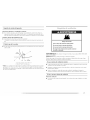
Dryer gas pipe
• The gas pipe that comes out through the rear of your dryer has a 3/8"male pipe thread.
A. ½" NPT gas supply line
B. _" NPT dryer pipe
*NOTE: If the dryer is mounted on a pedestal, the gas pipe height must be an additional 10"
(25.4 cm) or 1.>.._ (39.4 cm) from the floor, depending on the pedestal model. For a garage
installation, the gas pipe height must be an additional 18" (46 cm) from the floor.
¢)
Fire Hazard
Use a heavy metal vent.
Do not use a plastic vent.
Do not use a metal foil vent.
Failure to follow these instructions can result in death
or fire.
WARNING: Io reduce the risk of fire, this dryer MUS-] BE EXHAUSTED OUTDOORS.
IMPORTANT: Observe all governing codes and ordinances.
[he dryer exhaust must not be connected into any gas vent, chimney, wall, ceiling or a
concealed space of a building.
If using an existing vent system
• Clean lint from the entire length of the system and make sure exhaust hood is not plugged
with lint.
• Replace any plastic or metal foil vent with rigid or flexible heavy metal vent.
• Review Vent system chart. Modify existing vent system if necessary to achieve the best
drying performance.
If this is a new vent system
Vent material
• Use a heavy metal vent. Do not use plastic or metal foil vent.
• 4" (10.2 cm) heavy metal exhaust vent and clamps must be used.
4" ( 10.2 cm) heavy metal _'xhaust v_'nt
Vent products can be purchased from your dealer or by calling Maytag Services. For more
information, see the "Assistance or Service" section.
10

Rigid metal vent
• For best drying performance, rigid metal vents are recommended.
• Rigid metal vent is recommended to avoid crushing and kinking.
Flexible metal vent
• Flexible metal vents are acceptable only if accessible for cleaning.
• Flexible metal vent must lye fully extended and supported when the dryer is in its final
location.
• Remove excess flexible metal vent to avoid sagging and kinking that may result in
reduced airflow and poor performance.
• Do not install flexible metal vent in enclosed walls, ceilings or floors.
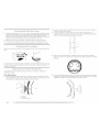
Elbows
45 ° elbows provide better airflow than 90 ° elbows.
Clamps
Good Better
Use clamps to seal all joints.
Exhaust vent must not be connected or secured with screws or other fastening devices
that extend into the interior of the duct. Do not use duct tape.
Clamp
Exhaust
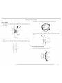
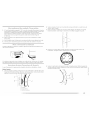
Recommended hood styles are shown here.
B
(10.2 cm)
A. Louv_'md hood style
B.Box hood style
The angled hood style (shown here) is acceptable.
4"
(10.2 cm)_
v_ 21/2"
(6.4 cm)
• An exhaust hood should cap the vent to keep rodents and insects from entering the home.
• Exhaust hood must lye at least 12" (30.5 cm) from the ground or any object that may be in
the path of the exhaust (such as flowers, rocks or bushes, snow line, etc./.
• Do not use an exhaust hood with a magnetic latch.
improper venting can cause moisture and lint to collect
indoors, which may result in:
[] Moisture damage to woodwork, furniture, paint, wallpaper,
carpets, etc.
[] Housecleaning problems and health problems.

Choose your exhaust installation type
Recommended exhaust installations
Typical installations vent the dryer from the rear of the dryer. Other installations are possible.
B
_ ...............D
A. Dryer
B. Elbow
C. Wall
D. Fxhaust hood
E. Clamps
£ Rigid metal or flexible metal vent
G. Vent length necessary to connect elbows
H. Exhaust outlet
Optional exhaust installations
This dryer can be converter] to exhaust out the right side, left side or through the bottom. If
you prefer, you may contact your local dealer to have the dryer converted.
Fire Hazard
Cover unused exhaust holes with one of the
following kits:
279818 (white)
279820 (black)
280102 (pacific blue)
Contact your local dealer.
Failure to follow these instructions can result in death,
fire, electrical shock, or serious injury.
B
A. Standard rear offset exhaust installation
B.Left or right side exhaust installation
C.Bottom exhaust h_stallation
Alternate installations for close clearances
Venting systems come in many varieties. Select the type best for your installation. Two close-
clearance installations are shown. Refer to the manufacturer's instructions.
\- _ _iiii.....
I //
i i u
A B
A. Over-the-top installation (also available with one
offset elbow)
B. Periscope installation
NOTE: The following kits for close clearance alternate installations are available for purchase.
Please see the "Assistance or Service" section to order.
• Over-the-lop Installation:
Part Number 4396028
• Periscope Installation (For use with dryer vent to wall vent mismatch):
Part Number 4396037 - 0" (0 cm) to 18" (45.72 cm) mismatch
Part Number 4396011 - 18" (45.72 cm) to 29" (73.66 cm) mismatch
Part Number 4396014- 29" (73.66 cm) to 50" (127 cm) mismatch
12

Special provisions for mobile home installations
The exhaust vent must be securely fastened to a noncombustible portion of the mobile home
structure and must not terminate beneath the mobile home. [erminate the exhaust vent
outside.
Determine vent path
• Select the route that will provide the straightest and most direct path outdoors.
• Plan the installation to use the fewest number of elbows and turns.
• When using elbows or making turns, allow as much room as possible.
• Bend vent gradually to avoid kinking.
• Use the fewest 90 ° turns possible.
Determine vent length and elbows needed for best drying performance
• Use tile following Vent system chart to determine type of vent material and hood
combinations acceptable to use.
NOTE: Do not use vent runs longer than those specified in the Vent system chart. Exhaust
systems longer than those specified will:
• Shorten the life of the dryer.
• Reduce performance, resulting in longer drying times and increased energy usage.
]he Vent system chart provides venting requirements that will help to achieve the best drying
performance.
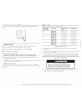
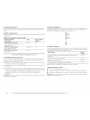
Vent system chart
NOTE: Side and bottom exhaust installations have a 90 ° turn inside the dryer. lb determine
maximum exhaust length, add one 90° turn to the chart.
Number of 90 ° Type of vent Box or Iouvered Angled hoods
turns or elbows hoods
0 Rigid metal 64 ft (20 m) 58 ft (17.7 m)
Flexible metal 36 ft (I 1 m) 28 ft/8.5 m)
1 Rigid metal 54 ft (16.5 m) 48 ft (14.6 m)
Flexible metal 31 ft (9.4 m) 23 ft (7 m)
2 Rigid metal 44 ft (I 3.4 m) 38 ft (11.6 m)
Flexible metal 27 ff (8.2 m) 19 ft (5.8 m)
3 Rigid metal 35 ft (10.7 m) 29 ft (8.8 m)
Flexible metal 25 ff (7.6 m) 17 ft (5.2 m)
4 Rigid metal 27 ff (8.2 m) 21 ft (6.4 m)
Flexible metal 23 ff (7 m) 15 ft (4.6 m)
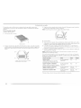
1. Install exhaust hood. Use caulking compound to seal exterior wall opening around
exhaust hood.
2. Connect vent to exhaust hood. Vent must fit inside exhaust hood. Secure vent to exhaust
hood with 4" (10.2 cm) clamp.
3. Run vent to dryer location. Use the straightest path possible. See "Determine vent path" in
"Plan V_nt System." Avoid 90_ turns. Use clamps to seal all joints. Do not use duct tape,
screws or other fastening devices that extend into the interior of the vent to secure vent.
Excessive Weight Hazard
Use two or more people to move and install dryer.
Failure to do so can result in back or other injury.
[b protect the floor, use a large flat piece of cardboard from the dryer carton. Place
cardboard under the entire back edge of the dryer.

2. Firmlygraspthebodyofthedryer.Gentlylaythedryeronthecardboard.Seeillustration. Acombinationofpipefittingsmustbeusedtoconnectthedryertotheexistinggasline.
Shownisarecommendedconnection.Yourconnectionmaylyedifferent,accordingtothe
supfylylinetype,sizeandlocation.
!
A
3.
Examine the leveling legs. Find the diamond marking.
-a
4. Screw the legs into tile leg holes by hand. Use a wrench to finish turning the legs until the 3.
diamond marking is no longer visible.
5. Place a carton corner post from dryer packaging under each of the 2 dryer back corners.
Stand the dryer up. Slide the dryer on the corner posts until it is close to its final location.
Leave enough room to connect the exhaust vent or gas line.
For mobile home use
Gas dryers must be securely fastened to the floor at the time of installation.
Mobile home installations require a Mobile Home [nstallation Kit. For more information,
please reference the service numbers in the "Assistance or Service" section.
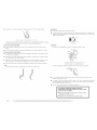
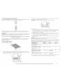
1.
2.
Remove the red cap from the gas pipe.
Using a wrench to tighten, connect the gas supply to the dryer. Use pipe-joint compound
on the threads of all non-flared male fittings. If flexible metal tubing is used, lye sure there
are no kinks.
A. Hated male fitting
B. Non-flared male" fitting
A. ?_" f/e'xib/_" gas connector
B. ?_" dryer pipe
C. %" to _" pipe elbow
D. _" pipe-to-flar_" adapter fitting
C
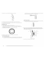
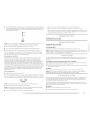
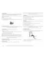
Open the shutoff valve in the supply line. The valve is open when the handle is parallel to
the gas pipe.
A. Closed valve
B.Open valve
]bst all connections by brushing on an approved noncorrosive leak-detection solution.
Bubbles will show a leak. Correct any leak found.
1. Using a 4" (10.2 cm) clamp, connect vent to exhaust outlet in dryer. ]f connecting to
existing vent, make sure the vent is clean. The dryer vent must fit over the dryer exhaust
outlet and inside the exhaust hood. Check that the vent is secured to exhaust hood with a
4" (10.2 cm) clamp.
2. Move dryer into its final location. Do not crush or kink vent.
3. (On gas models) Check that there are no kinks in the flexible gas line.
4. Once the exhaust vent connection is made, remove the corner posts and cardboard.
' I 0
:_,_ .....
Check the levelness of the dryer. Check levelness first side to side, then front to back.
NOTE: For LP gas connections, you must use pipe-joint compound resistant to the action
of [P gas. Do not use TEFLON '_ tape.
t:_TEFLON is a registeled tlademalk of E.I. Du Pont De Nemours and Company.
If the dryer is not level, prop up the dryer using a wood block. Use a wrench to adjust the legs
up or down and check again for levelness.
14

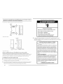
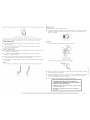
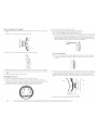
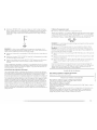
Youcanchangeyourdoorswingfromaright-sideopeningtoaleft-sideopening,ifdesired. 4. Remove the 6 screws to release the outer door assembly from the inner door assembly
/see illustration). It is important that you remove only the 6 indicated screws.
Remove the door
1. Open the dryer door. Remove the 4 screws that hold the door hinge oil the front panel of
the dryer. [.oosen, but do not remove, the screw with the top keyhole opening last (second
from the top).
2,
3.
A. Dryer
B.Do not remove.
C. Dryer door
lift and pull forward on the door so that the keyhole clears the screw head. Remove the
door.
lay the dryer door on a flat, protected surface with the inside door assembly facing up.
Remove the last screw from Step 1. Remove the 2 screws holding the handle to the door.
lift the inner door assembly off of the outer door assembly. Unsnap the handle from the
outer door assembly, move it to the other side, and snap in. Set the outer door assembly
aside.
\
Reverse the hinge and hinge bracket
1. Place the inner door, screw head side up, on the work surface.
2. Remove the 4 screws that hold the hinge to the door.

3. Removethe2screwsthatholdthehandlebrackettothedoor. scratchthedryersurface.Liftup.Repeatinthemiddleandatthebottom.Removethe
plugstripinthedooropeningandinsertintheoppositeside.
4. Movehingetotheothersideandreat_achwiththe4screwsremovedinStep2.
5. Movehandlebrackettotheothersideandreattachwiththe2screwsremovedinStep3.
6. Settheinnerdoorassemblyaside.
Reinstalling the door
1. Check for fingerprints on the glass. Clean if necessary.
2. Place the inner door assembly into the outer door assembly. Align the hinge in the
opening on the side. To fit correctly, the inside door assembly edge is completely inside
the outside door assembly edge.
3. Reassemble the inner and outer door assemblies with the 6 screws.
Style 2: Remove the label.
• Peel off the label located on the opposite side of the door opening covering the hinge
mounting holes. Apply the label over the original hinge holes.
6.
Insert a screw in the second opening from the top of the hinge opening and partially
tighten. Hang the door by placing the top hinge keyhole over the second screw head and
tighten the screw. By putting this screw in first, the door will hang in place while you
insert and tighten the remaining 4 screws.
4.
5.
Replace the 2 handle screws for the door handle of the door assembly.
Remove the plug strip or labeh
Style 1: Remove the plug strip.
• Use a small flat-blade screwdriver to remove the plug strip in the door opening. Slide
the head of the screwdriver under the top portion of the plug strip, being certain not to
A. Dryer door
B. Dryer
C. Insert this screw first.
7. Close the door and check that it latches securely.
16

ml: lele l ssIallalie s
1. Check that all parts are now instal led. If there is an extra part, go back through the steps to 6.
see which step was skipped. 7.
2. Check that you have all of your tools. 8.
3. Check the dryer's final location. Be sure the vent is not crushed or kinked. 9.
4. Check that the dryer is level. See "level Dryer." 10.
Electrical Shock Hazard
Plug into a grounded 3 prong outlet.
Do not remove ground prong.
Do not use an adapter.
Do not use an extension cord,
Failure to follow these instructions can result in death,
fire, or electrical shock.
11.
Remove any protective film or tape remaining on the dryer.
Dispose of/recycle all packaging materials.
Read "Dryer Use."
Wipe the dryer drum interior thoroughly with a damp cloth to remove any dust.
Select a Timed Dry heated cycle, and start the dryer. Do not select the Air Only
Temperature setting.
If the dryer will not start, check the following:
• Controls are set ill a running or "On" position.
• Start button has been pushed firmly.
• Dryer is plugged into a grounded 3 prong outlet.
• Electrical supply is connected.
• Household fuse is intact and tight, or circuit breaker has not tripped.
• Dryer door is closed.
When the dryer has been running for 5 minutes, open the dryer door and feel for heat. [f
you feel heat, cancel cycle and close doon If you do not feel heat, turn off the dryer and
check that the gas supply line shutoff valve is open.
• [f the gas supply line shutoff valve is closed, open it, then repeat the 5-minute test as
outlined above.
• [f the gas supply line shutoff valve is open, contact a qualified technician.
PY';i
3:1
5. Plug into a grounded 3 prong outlet. Turn on power.
!! lll:l{!_!!iii!iiii_ii!!iiiiiiiiiiiiii@_i_!_!_!_!i;ii_ii}ii_ii}ii_ii}ii_ii}ii_ii}ii_ii}ii_ii}ii_ii} i@!_!_!_!i!ii;::!!i!!!:i!!!17

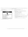
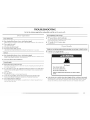
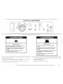
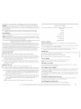
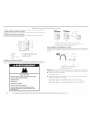
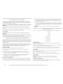
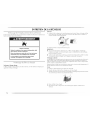
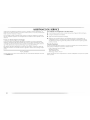
DRYER USE
High
AUTOMATIC MANUAL
CONTROL ON _ ) Estimated Ti.... _--
V
Heavy Duty CYCLES Timed Dry Remaining IO Medium
Wet O Casu Rapid Dry Less Air Only Off
Da'_qP O De[icateJ/(t_O_/ffSuper U _ _/ e ?
Cool Down O Dehcate
DRYNRSS TEMP EXTRA CYCLE
Extra Care 0 LEVEL CARE END
SIGNAL
Control Locked O Hold for 3
second_ to
lock / unlock Pause
control
Explosion Hazard
Keep flammable materials and vapors, such as
gasoline, away from dryer.
Do not dry anything that has ever had anything
flammable on it (even after washing).
Failure to follow these instructions can result in death,
explosion, or fire.
Fire Hazard
No washer can completely remove oil.
Do not dry anything that has ever had any type of oil on
it (including cooking oils).
items containing foam, rubber, or plastic must be dried
on a clothesline or by using an Air Cycle.
Failure to follow these instructions can result in death
or fire.
This manual covers several different models. Your dryer may not have all of the cycles and
features described.
The following is a guide to starting your dryer. Please refer to specific sections of this manual
for more detailed information.
1. Clean lint screen before each load. See "Cleaning the ].int Screen."
2. Place laundry in dryer and shut door.
3,
Rotate the dial to select either an Automatic or Manual Cycle then press the CONTROl.
ON button. The preset settings and drying time for the cycle chosen will be displayed.
To use an Automatic Cycle
• Point the dial to an Automatic Cycle,
18

Select DRYNESS I.EVEI to adjust how dry you want the load to be. The time displayed
is an estimated length of the cycle based on the Dryness Level selected. As the cycle
runs, the control senses the dryness of the load and adjusts the time automatically for
the selected Dryness Level.
I ore
Less
O
DRYNESS
LEVEL
NOTE: Time is not adjustable for Automatic Cycles. Pressing the Manual Dry Time l- or +2
buHons will cause a triple beep, indicating that the time cannot be changed.
• Press the EXTRA CARE feature button if this option is desired.
• Press the CYCI.E END SIGNAl button to set signal volume to desired level.
• Press and hold HOlD TO START button until dryer starts (about 1 second).
Once an Automatic Cycle has started, the Extra Care feature and the Cycle End Signal
level can be adjusted. Press the OFF key twice to stop the dryer and clear the settings,
allowing you to select another cycle and Dryness [eveh
How Automatic Cycles Work
This feature improves drying performance with Auto Moisture Sensing Plus, which
advances the cycle as moisture is extracted from clothing. A thermistor (electronic
temperature sensor) and moisture sensing strips in the dryer drum help measure the
amount of moisture in the clothes as they tumble. An electronic control determines the
load type to help save time, avoid overdrying, and increase the accuracy of the end
dryness level. After the first 5 minutes of an automatic cycle, the estimated time display
will adjust based on the approximate load size, cycle, dryness level selected and amount
of moisture left in the clothes. When the clothes have reached approximately 80% of the
dryness level selected, the estimated time display will adjust again, showing the final
drying time. Auto Moisture Sensing Plus takes the guesswork out of drying time and
enhances fabric care.
To use a Manual Cycle
• Rotate the dial to select a Manual Cycle.
Press the MANUAl DRY TIME (- or +) buttons until the desired drying time is displayed.
[_p - or +, and the time will change by 1-minute intervals. Press and hold - or +, and the
time will change by 5-minute intervals. The initial time displayed is the actual drying time.
DRY TIME
NOTE: The Manual Dry Time feature can be used only with Manual Cycles.
• Press TEMP until the desired temperature illuminates.
NOTE: Pressing the Dryness I.evel button will cause the triple beep indicating that this
option is not selectable. Also, a Dryness level is not indicated.
• Press the EXTRA ([ARE feature button if this option is desired.
• Press the CYCI.E END SIGNAl button to set volume to desired level.
• Press and hold HOLD TO START button until dryer starts (about I second).
While a Manual Cycle is running, you can change the settings for Time, 1emperature, the
Extra Care feature, and the Cycle End Signal. Press the OFF button twice to stop the dryer
and clear the settings, allowing you to select another cycle.
TO stop your dryer at any time
Press OFF twice or open the door.
TO pause the dryer at any time
Open the door or press OFF once.
To restart the dryer
Close the door and press and hold HOLD TO START button until dryer starts. ......
NOTE: Drying will continue from where the cycle was interrupted if you close the door and ,i
press Start within 5 minutes, if the cycle is interrupted for more than 5 minutes, the dryer will
shut off. Select new cycle settings before restarting the dryer.
This feature allows you to lock your settings to avoid unintended use of the dryer. You can also
use the Control locked feature to avoid unintended cycle or option changes during dryer
operation.
To enable the Control Locked feature when dryer is running:
Press and hold the CYCLE END SIGNAl. button for _ seconds. The control is locked when a
single beep is heard and the Control [.ocked status light is on.
• When the dryer is off, it is not necessary to press the Control On button before activating
the Control [ocked feature.
To unlock:
Press and hold the CYCLE END SIGNAL button for 3 seconds to turn this feature off.
NOTE: When the dryer is running and Control [.ocked is on, the dryer can be stopped by
pressing the Off button, but can't be restarted until the control is unlocked.
...... ==_;; ............. 7' ..... II l:t'_
E)
Select the correct cycle and dryness level or temperature for your load. If an Automatic Cycle
is running, the display shows the estimated cycle time when your dryer is automatically
sensing the dryness level of your load. [f a Manual Cycle is running, the display shows the
exact number of minutes remaining in the cycle.
Cool [::)own tumbles the load without heat during the last few minutes of all cycles. Cool
[::)own makes the loads easier to handle and reduces wrinkling. [he length of the Cool Down
depends on the load size and dryness level.
Drying tips
• Follow care label directions when they are available.
• If desired, add a fabric softener sheet. Follow package instructions.

• Removetheloadfromthedryerassoonastumblingstopstoreducewrinkling.Thisis
especiallyimportantforpermanentpress,knitsandsyntheticfabrics.
• Avoiddryingheavyworkclotheswithlighterfabrics.Thiscouldcauseoverdryingof
lighterfabrics,leadingtoincreasedshrinkingorwrinkling.
Cycle tips
• Dry most loads using the preset cycle settings.
• Refer to the Automatic or Manual Preset Cycle Settings chart (in the "Cycles" section) for a
guide to drying various loads.
• Drying temperature and Dryness Level are preset when you choose an Automatic
Cycle. You can choose a different dryness level, depending on your load by pressing
the DRYNESS lEVEE button to select MORE or lESS.
• If you wish to adjust the cycle length of a Manual Cycle, you must press the MANUAl
DRY TIME (- or +) buttons. Adjust the temperature of a Manual Cycle by pressing
TEMP until the desired temperature is selected.
NOTE: You cannot choose a Dryness level with Manual Cycles.
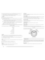
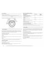
C_P _ /I,_/__"'_ __g
You may follow the progress of your dryer with the drying status indicator lights.
Sensing 0
Wet O
Damp O
Cool Down O
Cycle Complete O
Extra Care O
Control Locked O
Sensing
When a cycle is first turned on, tile Sensing light illuminates until a wet item is detected.
• In an Automatic Cycle, if a wet item has not been detected within 10 minutes, the Sensing
light will turn off and the dryer will shut down.
• In a Manual Cycle, if a wet item is not detected after 10 minutes the Wet light turns on
and the selected cycle continues.
Wet
The Wet light will turn on when a wet item has been detected in the dryer. [he Wet light will
remain on until:
• [he damp dry point is reached in an Automatic Cycle.
• [he dryer enters the cool down period in a Manual Cycle.
Damp
The Damp light indicates that the load has reached the damp dry level.
NOTE: The Damp light is not used with Manual Cycles.
Cool Down
The Cool Down light illuminates during the cool down part of the cycle, laundry is cooling
down for ease in handling.
Cycle Complete
The Cycle Complete light illuminates when a drying cycle is finished. If the Extra Care feature
has been selected, the Extra Care feature indicator light will also be on.
The Cycle Complete light turns off 1 hour after the end of a drying cycle (including the Extra
Care cycle of 2 hours), when Off is pressed, or when the door is opened.
Extra Care Feature
[he Extra Care feature light illuminates when this option is selected. This indicator stays on
with the Cycle Complete light.
Control Locked
[he Control Locked light illuminates when this option is enabled.
Indicator lights
Other indicator lights on the control panel show Cycle, ]emperature and Cycle End Signal
settings selected.
The time display will indicate the estimated or actual time remaining in a cycle.
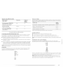
Select the drying cycle that matches the type of load you are drying. See Automatic preset or
Manual preset cycle settings charts.
AUTOMATIC
Heavy Duty
Normal
Casual
Delicate v
Delicate
CYCLES
MANUAL
Timed Dry
, Touchup
I _ Rapid Dry
Cycle Ck;ntrol knob
Automatic Cycles
Automatic Cycles allow you to match the cycle to the load you are drying. See the following
Automatic preset cycle settings chart. Each cycle dries certain fabrics at the recommended
temperature. A sensor detects the moisture in the load and automatically adjusts the drying
time for optimal drying.
Heavy Duty
Use this cycle to get High heat for heavyweight mixed loads, cotton towels or jeans.
2 0
La page est en cours de chargement...
La page est en cours de chargement...
La page est en cours de chargement...
La page est en cours de chargement...
La page est en cours de chargement...
La page est en cours de chargement...
La page est en cours de chargement...
La page est en cours de chargement...
La page est en cours de chargement...
La page est en cours de chargement...
La page est en cours de chargement...
La page est en cours de chargement...
La page est en cours de chargement...
La page est en cours de chargement...
La page est en cours de chargement...
La page est en cours de chargement...
La page est en cours de chargement...
La page est en cours de chargement...
La page est en cours de chargement...
La page est en cours de chargement...
La page est en cours de chargement...
La page est en cours de chargement...
La page est en cours de chargement...
La page est en cours de chargement...
La page est en cours de chargement...
La page est en cours de chargement...
La page est en cours de chargement...
La page est en cours de chargement...
La page est en cours de chargement...
La page est en cours de chargement...
La page est en cours de chargement...
La page est en cours de chargement...
La page est en cours de chargement...
La page est en cours de chargement...
La page est en cours de chargement...
La page est en cours de chargement...
La page est en cours de chargement...
La page est en cours de chargement...
La page est en cours de chargement...
La page est en cours de chargement...
La page est en cours de chargement...
La page est en cours de chargement...
La page est en cours de chargement...
La page est en cours de chargement...
La page est en cours de chargement...
La page est en cours de chargement...
La page est en cours de chargement...
La page est en cours de chargement...
La page est en cours de chargement...
La page est en cours de chargement...
La page est en cours de chargement...
La page est en cours de chargement...
La page est en cours de chargement...
La page est en cours de chargement...
La page est en cours de chargement...
La page est en cours de chargement...
La page est en cours de chargement...
La page est en cours de chargement...
La page est en cours de chargement...
La page est en cours de chargement...
La page est en cours de chargement...
La page est en cours de chargement...
La page est en cours de chargement...
La page est en cours de chargement...
-
 1
1
-
 2
2
-
 3
3
-
 4
4
-
 5
5
-
 6
6
-
 7
7
-
 8
8
-
 9
9
-
 10
10
-
 11
11
-
 12
12
-
 13
13
-
 14
14
-
 15
15
-
 16
16
-
 17
17
-
 18
18
-
 19
19
-
 20
20
-
 21
21
-
 22
22
-
 23
23
-
 24
24
-
 25
25
-
 26
26
-
 27
27
-
 28
28
-
 29
29
-
 30
30
-
 31
31
-
 32
32
-
 33
33
-
 34
34
-
 35
35
-
 36
36
-
 37
37
-
 38
38
-
 39
39
-
 40
40
-
 41
41
-
 42
42
-
 43
43
-
 44
44
-
 45
45
-
 46
46
-
 47
47
-
 48
48
-
 49
49
-
 50
50
-
 51
51
-
 52
52
-
 53
53
-
 54
54
-
 55
55
-
 56
56
-
 57
57
-
 58
58
-
 59
59
-
 60
60
-
 61
61
-
 62
62
-
 63
63
-
 64
64
-
 65
65
-
 66
66
-
 67
67
-
 68
68
-
 69
69
-
 70
70
-
 71
71
-
 72
72
-
 73
73
-
 74
74
-
 75
75
-
 76
76
-
 77
77
-
 78
78
-
 79
79
-
 80
80
-
 81
81
-
 82
82
-
 83
83
-
 84
84


Maytag EPIC Z MGD9800TB0 Manuel utilisateur
- Catégorie
- Sèche-linge
- Taper
- Manuel utilisateur
- Ce manuel convient également à
dans d''autres langues
Documents connexes
-
Maytag MGDZ600TK1 Le manuel du propriétaire
-
-
Maytag MGD5770TQ1 Le manuel du propriétaire
-
-
-
-
-
-
-