Maytag MDE25PDAYW Installation Instructions Manual
- Catégorie
- Sèche-linge électriques
- Taper
- Installation Instructions Manual
Ce manuel convient également à

INSTALLATION INSTRUCTIONS
COMMERCIAL DRYER – Gas or Electric
INSTRUCTIONS POUR L’INSTALLATION D’UNE
SÉCHEUSE COMMERCIALE – À gaz ou électrique
Table of Contents/Table des matières . . . . . . . . . . . . . . . . . . . . . . . . . . . . . . . . . . . . . . . . 2
W10135154B
www.maytagcommerciallaundry.com
W10135154B EnFrv10.qxd:YB70809-10135134A 4/20/10 2:42 PM Page 1

2
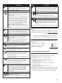
You can be killed or seriously injured if you don't immediately
You
can be killed or seriously injured if you don't
follow
All safety messages will tell you what the potential hazard is, tell you how to reduce the chance of injury, and tell you what can
happen if the instructions are not followed.
Your safety and the safety of others are very important.
We have provided many important safety messages in this manual and on your appliance. Always read and obey all safety
messages.
This is the safety alert symbol.
This symbol alerts you to potential hazards that can kill or hurt you and others.
All safety messages will follow the safety alert symbol and either the word “DANGER” or “WARNING.”
These words mean:
follow instructions.
instructions.
DANGER
WARNING
TABLE OF CONTENTS
DRYER SAFETY............................................................................ 2
INSTALLATION REQUIREMENTS .............................................. 4
T
ools and Parts .......................................................................... 4
Location Requirements.............................................................. 5
Electrical Requirements ............................................................ 6
Gas Supply Requirements ........................................................ 9
Venting Requirements ............................................................ 10
INSTALLATION INSTRUCTIONS – GAS DRYER .................. 12
Make Gas Connection..............................................................12
Connect Vent ............................................................................12
Complete Installation ..............................................................12
INSTALLATION INSTRUCTIONS – ELECTRIC DRYER........ 13
Make Electrical Connection......................................................13
Connect Vent ............................................................................20
Complete Installation ..............................................................20
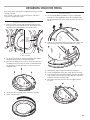
REVERSING THE DOOR SWING .......................................... 21
MAINTENANCE INSTRUCTIONS .......................................... 22
ELECTRONIC CONTROL SETUP .......................................... 23
WARRANTY ............................................................................ 27
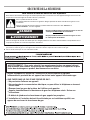
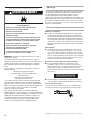
DRYER SAFETY
FOR YOUR SAFETY
Do not store or use gasoline or other flammable vapors and liquids in the vicinity of this or any other appliance.
■ It is recommended that the owner post, in a prominent location, instructions for the customer’s use in the event the customer smells
gas. This information should be obtained from your gas supplier.
■ Post the following warning in a prominent location.
TABLE DES MATIÈRES
SÉCURITÉ DE LA SÉCHEUSE ..............................................28
EXIGENCES D’INSTALLATION................................................30
O
utillage et pièces ....................................................................30
Exigences d’emplacement ......................................................31
Spécifications électriques .......................................................32
Spécifications de l’alimentation en gaz ..................................34
Exigences concernant l’évacuation ..........................................35
INSTRUCTIONS D’INSTALLATION – SÉCHEUSE À GAZ ....37
Raccordement à la canalisation de gaz ..................................37
Raccordement du conduit d’évacuation ................................37
Achever l’installation ................................................................37
INSTRUCTIONS D’INSTALLATION – SÉCHEUSE
ÉLECTRIQUE............................................................................38
Raccordement du conduit d’évacuation ................................38
Achever l’installation ................................................................38
INVERSION DU SENS D’OUVERTURE DE LA PORTE............39
INSTRUCTIONS D’ENTRETIEN ..............................................41
RÉGLAGE DE COMMANDE ÉLECTRONIQUE ......................42
GARANTIE ................................................................................47
W10135154B EnFrv10.qxd:YB70809-10135134A 4/20/10 2:42 PM Page 2

WARNING: For your safety, the information in this manual must be followed to minimize
the risk of fire or explosion, or to prevent property damage, personal injury, or death.
– Do not store or use gasoline or other flammable vapors and liquids in the vicinity of this
or any other appliance.
– WHAT TO DO IF YOU SMELL GAS:
•
Do not try to light any appliance.
•
Do not touch any electrical switch; do not use any phone in your building.
•
Immediately call your gas supplier from a neighbor's phone. Follow the gas supplier's
instructions.
•
If you cannot reach your gas supplier, call the fire department.
– Installation and service must be performed by a qualified installer, service agency, or
the gas supplier.
•
Clear the room, building, or area of all occupants.
In the State of Massachusetts, the following installation instructions apply:
■ Installations and repairs must be performed by a qualified or licensed contractor, plumber, or gasfitter qualified or licensed by
the State of Massachusetts.
■ If using a ball valve, it shall be a T-handle type.
■ A flexible gas connector, when used, must not exceed 3 feet.
WARNING: Gas leaks cannot always be detected by smell.
Gas suppliers recommend that you use a gas detector approved by UL or CSA.
For more information, contact your gas supplier.
If a gas leak is detected, follow the “What to do if you smell gas” instructions.
3
W10135154B EnFrv10.qxd:YB70809-10135134A 4/20/10 2:42 PM Page 3

4
INSTALLATION REQUIREMENTS
Tools and Parts
Gather the required tools and parts before starting installation.
Read and follow the instructions provided with any tools
listed here.
Tools needed
■ 8" or 10" Pipe wrench
■ 8" or 10" adjustable wrench
■ Flat-blade screwdriver
■ Phillips screwdriver
✮ TORX
®†
20 SECURITY SCREWDRIVER OR BIT
■ Adjustable wrench that opens to 1" (25 mm) or 1" (25 mm)
hex-head socket wrench
■ Level
■ 5/16" socket wrench
■ Utility knife
■ Vent clamps
■ Pipe-joint compound resistant to LP gas
■ Caulk gun and caulk (for installing new exhaust vent)
■ Pliers
■ Putty knife
Parts supplied
Remove parts bag from dryer drum. Check that all parts were
included.
■ Foot boot (4)
■ Dryer foot (4)
■ PD models: Cam for service door lock
PR models: Card reader bezel, card reader wire harness,
hardware
IMPORTANT: The gas installation must conform with local codes, or in the absence of local codes, with the National Fuel Gas
Code, ANSI Z223.1/NFPA 54 or the Canadian Natural Gas and Propane Installation Code, CSA B149.1.
The dryer must be electrically grounded in accordance with local codes, or in the absence of local codes, with the National
Electrical Code, ANSI/NFPA 70 or Canadian Electrical Code, CSA C22.1.
†® TORX is a registered trademark of Acument Intellectual Properties, LLC.
W10135154B EnFrv10.qxd:YB70809-10135134A 4/20/10 2:42 PM Page 4

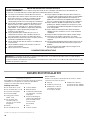
C
loset
door
5
Location Requirements
If installing a gas dryer:
IMPORTANT: Observe all governing codes and ordinances.
■ Check code requirements: Some codes limit or do not permit
installation of clothes dryers in garages, closets, or sleeping
quarters. Contact your local building inspector.
■ Make sure that lower edges of the cabinet, plus the back and
bottom sides of the dryer, are free of obstructions to permit
adequate clearance of air openings for combustion air. See
“Recessed Area and Closet Installation Instructions” below
for minimum spacing requirements.
NOTE: The dryer must not be installed in an area where it will
be exposed to water and/or weather.
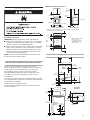
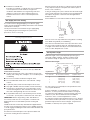
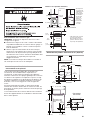
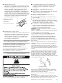
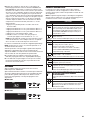
Recessed Area and Closet Installation Instructions
This dryer may be installed in a recessed area or closet.
For recessed area and closet installations, minimum clearances
can be found on the warning label on the rear of the dryer.
The installation spacing is in inches and is the minimum
allowable. Additional spacing should be considered for ease
of installation, servicing, and compliance with local codes
and ordinances.
If closet door is installed, the minimum unobstructed air opening
in the top and bottom is required. Louvered doors with equivalent
air openings are acceptable.
The dryer must be exhausted outdoors.
No other fuel-burning appliance may be installed in the same
closet as the dryer.
R
ecessed front view
C
loset side view
Minimum Installation Clearances
*Additional clearances for wall, door, and floor moldings may be required
or if external exhaust elbow is used.
closet
d
oor
F
ront
V
iew
3" (76 mm)
3
" (76 mm)
2
4 in
2
(1.55 m
2
)*
48 in
2
.
(
3.1 m
2
)
*
*
Opening is the minimum
f
or a closet door.
L
ouvered doors with
equivalent air openings
are acceptable.
14"
(356 mm)
m
ax.
1" (25 mm)
0
" (0 mm)
1
5"
(381 mm)*
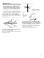
Product Dimensions 27" (68.6 cm) dryer
28
3
⁄4"
(733 mm)
6
1
⁄4"
(159 mm)
ELECTRIC
GAS
EXHAUST
LEFT OR
RIGHT SIDE
EXHAUST
4
1
⁄4"
(108 mm)
13"
(330 mm)
1
1
⁄4"
(32 mm)
BACK
VIEW
4
1
⁄4" (108 mm)
6
3
⁄4"
(152 mm)
4" (102 mm)
dia.
3/4" (21 mm)
SIDE VIEW
BOTTOM
EXHAUST
35"
(889 mm)
27
1
⁄4" (695 mm)
29" (736 mm)
14
1
⁄8"
(359 mm)
7
1
⁄4"
(184 mm)
10
1
⁄4"
(260 mm)
27" (686 mm)
0" (0 mm)
0" (0 mm)
7
7
⁄8"
(200 mm)
W10135154B EnFrv10.qxd:YB70809-10135134A 4/20/10 2:42 PM Page 5

6
Electrical Requirements – Gas Dryer
IMPORTANT: The dryer must be electrically grounded in
accordance with local codes and ordinances or, in the absence of
local codes, with the National Electrical Code, ANSI/NFPA 70,
latest edition, or Canadian Electrical Code, CSA C22.1.
If codes permit and a separate ground wire is used, it is
recommended that a qualified electrical installer determine that
the ground path is adequate.
A copy of the above code standards can be obtained from:
National Fire Protection Association
One Batterymarch Park, Quincy, MA 02269
CSA International
8501 East Pleasant Valley Road
Cleveland, Ohio 44131-5575
■ A 120 volt, 60 Hz, AC only, 15- or 20-amp, fused electrical
circuit is required. A time-delay fuse or circuit breaker is also
recommended. It is recommended that a separate circuit
serving only this dryer be provided.
Recommended Ground Method
The dryer, when installed, must be electrically grounded in
a
ccordance with local codes or, in the absence of local codes,
with the National Electrical Code, ANSI/NFPA 70, latest edition,
or Canadian Electrical Code, CSA C22.1, and all local codes
a
nd ordinances.
GROUNDING INSTRUCTIONS
SAVE THESE INSTRUCTIONS
■
For a grounded, cord-connected dryer:
This dryer must be grounded. In the event of malfunction or
breakdown, grounding will reduce the risk of electric shock
by providing a path of least resistance for electric current.
T
his dryer is equipped with a cord having an equipment-
grounding conductor and a grounding plug. The plug must
be plugged into an appropriate outlet that is properly
installed and grounded in accordance with all local codes
and ordinances.
WARNING: Improper connection of the equipment-
grounding conductor can result in a risk of electric shock.
Check with a qualied electrician or service representative
or personnel if you are in doubt as to whether the dryer is
properly grounded. Do not modify the plug provided with
the dryer: if it will not t the outlet, have a proper outlet
installed by a qualied electrician.
W10135154B EnFrv10.qxd:YB70809-10135134A 4/20/10 2:42 PM Page 6

7
Electrical Requirements – U.S.A. Only
It is your responsibility
■ To contact a qualified electrical installer.
■ To be sure that the electrical connection is adequate and in
conformance with the National Electrical Code, ANSI/NFPA
70-latest edition and all local codes and ordinances.
The National Electrical Code requires a 4-wire power supply
connection for homes built after 1996, dryer circuits involved
in remodeling after 1996, and all mobile home installations.
A copy of the above code standards can be obtained from:
National Fire Protection Association, One Batterymarch Park,
Q
uincy, MA 02269.
■ To supply the required 3 or 4 wire, single phase, 120/240 volt,
60 Hz., AC only electrical supply (or 3 or 4 wire, 120/208 volt
electrical supply, if specified on the serial/rating plate) on a
separate 30-amp circuit, fused on both sides of the line. A
time-delay fuse or circuit breaker is recommended. Connect
to an individual branch circuit. Do not have a fuse in the
neutral or grounding circuit.
■ Do not use an extension cord.
■ If codes permit and a separate ground wire is used, it is
recommended that a qualified electrician determine that the
ground path is adequate.
Electrical Connection
To properly install your dryer, you must determine the type of
electrical connection you will be using and follow the instructions
provided for it here.
■ This dryer is manufactured ready to install with a 3-wire
electrical supply connection. The neutral ground conductor is
permanently connected to the neutral conductor (white wire)
within the dryer. If the dryer is installed with a 4-wire electrical
supply connection, the neutral ground conductor must be
removed from the external ground connector (green screw),
and secured under the neutral terminal (center or white wire)
of the terminal block. When the neutral ground conductor is
secured under the neutral terminal (center or white wire) of the
terminal block, the dryer cabinet is isolated from the neutral
conductor.
■ If local codes do not permit the connection of a neutral
ground wire to the neutral wire, see “Optional 3-wire
connection” section.
■ A 4-wire power supply connection must be used when the
appliance is installed in a location where grounding through
the neutral conductor is prohibited. Grounding through the
neutral is prohibited for (1) new branch-circuit installations, (2)
mobile homes, (3) recreational vehicles, and (4) areas where
local codes prohibit grounding through the neutral conductor.
If using a power supply cord:
Use a UL listed power supply cord kit marked for use with
c
lothes dryers. The kit should contain:
■ A UL listed 30-amp power supply cord, rated 120/240 volt
minimum. The cord should be type SRD or SRDT and be at
least 4 ft (1.22 m) long. The wires that connect to the dryer
must end in ring terminals or “U” shaped spade terminals
with upturned ends.
■ A UL listed strain relief.
If your outlet looks like this:
Then choose a 4-wire power supply cord with ring or spade
terminals and UL listed strain relief. The 4-wire power supply
cord, at least 4 ft (1.22 m) long, must have four 10-gauge copper
wires and match a 4-wire receptacle of NEMA Type 14-30R. The
ground wire (ground conductor) may be either green or bare. The
neutral conductor must be identified by a white cover.
If your outlet looks like this:
4-wire receptacle (14-30R)
3-wire receptacle (10-30R)
Then choose a 3-wire power supply cord with ring or spade
terminals and UL listed strain relief. The 3-wire power supply
cord, at least 4 ft (1.22 m) long, must have three 10-gauge copper
wires and match a 3-wire receptacle of NEMA Type 10-30R.
W10135154B EnFrv10.qxd:YB70809-10135134A 4/20/10 2:42 PM Page 7

8
Electrical Requirements – Canada Only
It is your responsibility
■ To contact a qualified electrical installer.
■ To be sure that the electrical connection is adequate and in
conformance with the Canadian Electrical Code, C22.1-latest
edition and all local codes. A copy of the above codes
standard may be obtained from: Canadian Standards
Association, 178 Rexdale Blvd., Toronto, ON M9W 1R3
CANADA.
4-wire receptacle (14-30R)
If connecting by direct wire:
Power supply cable must match power supply (4-wire or 3-wire)
and be:
■ Flexible armored cable or nonmetallic sheathed copper cable
(with ground wire), protected with flexible metallic conduit. All
current-carrying wires must be insulated.
■ 10-gauge solid copper wire (do not use aluminum).
■ At least 5 ft (1.52 m) long.
■ Do not use an extension cord.
If you are using a replacement power supply cord, it is
recommended that you use Power Supply Cord Replacement
Part Number 8579325. For further information, please
reference the service numbers located in the “Assistance
or Service” section.
GROUNDING INSTRUCTIONS
SAVE THESE INSTRUCTIONS
■
For a grounded, cord-connected dryer:
This dryer must be grounded. In the event of malfunction or
breakdown, grounding will reduce the risk of electric shock
by providing a path of least resistance for electric current.
This dryer is equipped with a cord having an equipment-
grounding conductor and a grounding plug. The plug must
be plugged into an appropriate outlet that is properly
installed and grounded in accordance with all local codes
and ordinances.
WARNING: Improper connection of the equipment-
grounding conductor can result in a risk of electric shock.
Check with a qualied electrician or service representative
or personnel if you are in doubt as to whether the dryer is
properly grounded. Do not modify the plug provided with
the dryer: if it will not t the outlet, have a proper outlet
installed by a qualied electrician.
■ To supply the required 4 wire, single phase, 120/240 volt, 60
Hz., AC only electrical supply on a separate 30-amp circuit,
fused on both sides of the line. A time-delay fuse or circuit
breaker is recommended. Connect to an individual branch
circuit.
■ This dryer is equipped with a CSA International Certified
Power Cord intended to be plugged into a standard 14-30R
wall receptacle. The cord is 5 ft (1.52 m) in length. Be sure
wall receptacle is within reach of dryer’s final location.
W10135154B EnFrv10.qxd:YB70809-10135134A 4/20/10 2:42 PM Page 8

9
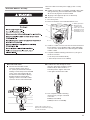
F
lexible metal appliance connector:
■ It is recommended that a new flexible stainless steel gas line,
design-certified by CSA International, be used for connecting
the dryer to the gas supply line. (The gas pipe which extends
through the lower rear of the dryer is provided with
3
⁄8" male
pipe thread.)
■ Do not kink or damage the flexible stainless steel gas line
when moving the dryer.
Rigid pipe connection:
The rigid pipe connection requires a combination of pipe fittings
to obtain an in-line connection to the dryer.
■ Must include a shutoff valve:
The supply line must be equipped with a manual shutoff
valve installed within 6 ft. (1.8 m) of dryer in accordance
with National Fuel Gas Code, ANSI Z223.1. In Canada,
an individual manual shutoff valve must be installed in
accordance with the B149 installation codes CAN/CGA
B149.1 and CAN/CGA B149.2. This valve should be located
in the same room as the dryer. It should be in a location that
allows ease of opening and closing. Do not block access to
shutoff valve. The valve is for turning on or shutting off gas
to the dryer.
D
C
A B
Gas Supply Line
Recommended method
■ Provide a gas supply line of 1/2" rigid (IPS) pipe to the dryer
l
ocation. Pipe joint compounds that resist the action of LP gas
must be used. Do not use TEFLON
®
†
tape. With LP gas,
piping or tubing size can be 1/2" minimum. Usually, LP gas
s
uppliers determine the size and materials used in the system.
Alternate method
■ The gas supply may also be connected using 3/8" approved
copper or aluminum tubing. If the total length of the supply
line is more than 20 ft. (6.1 m), larger tubing will be required.
If using natural gas, do not use copper tubing. Pipe joint
compounds that resist the action of LP gas must be used.
†®TEFLON is a registered trademark of E.I. Du Pont De Nemours and Company.
Gas Supply Requirements
IMPORTANT: Observe all governing codes and ordinances.
This installation must conform with all local codes and
ordinances. In the absence of local codes, installation must
conform with American National Standard, National Fuel Gas
Code ANSI Z223.1/NFPA 54 or CAN/CSA B149.
A copy of the above code standards can be obtained from:
National Fire Protection Association
One Batterymarch Park, Quincy, MA 02269
CSA International
8501 East Pleasant Valley Road
Cleveland, Ohio 44131-5575
The design of this dryer has been certified by CSA International
for use at altitudes up to 10,000 feet (3048 m) above sea level at
the B.T.U. rating indicated on the model/serial plate. Burner input
adjustments are not required when the dryer is operated up to
this elevation.
When installed above 10,000 feet (3048 m), a four percent (4%)
reduction of the burner B.T.U. rating shown on the model/serial
plate is required for each 1,000 foot (305 m) increase in elevation.
For assistance when converting to other gas types and/or
installing above 10,000 feet (3048 m) elevation, contact your
local service company.
Type of Gas
This dryer is equipped for use with natural gas. It is design-
certified by CSA International for LP (propane and butane) gases
with appropriate conversion. No attempt shall be made to convert
the dryer from the gas specified on the serial/rating plate for use
with a different gas without consulting the serving gas supplier.
Conversion must be done by a qualified service technician.
Gas conversion kit part numbers are listed on the gas valve
burner base.
A. Gas supply line
B. Shutoff valve in “open” position
C. To dryer
D. NPT 1/8" min. plugged tapping
W10135154B EnFrv10.qxd:YB70809-10135134A 4/20/10 2:42 PM Page 9

10
■ Installed in a confined area:
If the dryer is installed in a confined area such as a bathroom
or closet, provision must be made for enough air for
combustion and ventilation. Check governing codes and
ordinances or refer to the “Recessed Area and Closet
Installation Instructions” in the “Location Requirements”
section.
Gas Supply Pressure Testing
A 1/8" NPT minimum plugged tapping, accessible for gauge
testing, must be installed immediately downstream of the installed
shut-off valve to the dryer.
The dryer must be disconnected from the gas supply piping
s
ystem during any pressure testing of the system at test
pressures in excess of 1/2" psig.
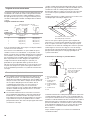
Venting Requirements
WARNING: To reduce the risk of fire, this dryer MUST BE
EXHAUSTED OUTDOORS.
■ The dryer exhaust must not be connected into any gas vent,
chimney, wall, ceiling, attic, crawlspace, or a concealed space
of a building.
■ Do not use an exhaust hood with a magnetic latch.
■ Do not install flexible metal vent in enclosed walls, ceilings,
or floors.
■ 4" (102 mm) heavy metal vent and clamps must be used.
■ Only rigid or flexible metal vent shall be used for exhausting.
■ Use clamps to seal all joints. Do not use duct tape, screws,
or other fastening devices that extend into the interior of the
vent. Items sticking through the vent can catch lint.
■ If only flexible metal vent is used, the back pressure should
not exceed 1" (25 mm) water column at the rear of the dryer.
IMPORTANT: Observe all governing codes and ordinances.
Use a heavy metal vent. Do not use plastic or metal foil vent.
Rigid metal vent is recommended to prevent crushing and
kinking.
Flexible metal vent must be fully extended and supported when
the dryer is in its final position. Remove excess flexible metal vent
to avoid sagging and kinking that will result in reduced airflow and
poor performance.
An exhaust hood should cap the vent to prevent rodents and
insects from entering the home or business.
Exhaust hood must be at least 12" (305 mm) from the ground
or any object that may be in the path of the exhaust (such as
flowers, rocks, or bushes).
If using an existing vent system, clean lint from the entire length
of the system and make sure exhaust hood is not plugged with
lint. Replace any plastic or metal foil vent with rigid metal or
flexible metal vent.
Plan installation to use the fewest number of elbows and turns.
Allow as much room as possible when using elbows or making
turns. Bend vent gradually to avoid kinking.
Vent outlet is located at the back of the dryer, at bottom center.
The vent can be routed up, down, left, right, behind the dryer,
or straight out the back of the dryer. See “Product Dimensions”
in the “Location Requirements” section.
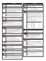
Vent System Length
Maximum length of vent system depends upon the type of
vent used, number of elbows, and type of exhaust hood.
The maximum length for rigid vent is shown in the chart.
For vent systems not covered by the vent specification chart,
see your parts distributor.
If dryer is installed in a confined area, such as a bedroom,
bathroom, or closet, provision must be made for enough air
for combustion and ventilation. (Check governing codes and
ordinances.) See “Recessed Area and Closet Installation
Instructions” in the “Location Requirements” section.
A 4" (102 mm) outlet hood is preferred. However, a 2
1
⁄2" (64 mm)
outlet exhaust hood may be used. A 2
1
⁄2" (64 mm) outlet creates
greater back pressure than other hood types. For permanent
installation, a stationary vent system is required.
A
B
Exhaust Air Flow
A. Good
B. Better
Rigid Metal Vent
No. of 90° turns
4" (102 mm) Diameter Exhaust Hoods
Maximum Vent Length
0
1
2
3
4
Box Hood and Louvered Style Angled Hood Style
130 ft. (39.6 m)
125 ft. (38.1 m)
115 ft. (35.1 m)
106 ft. (32.3 m)
98 ft. (29.9 m)
129 ft. (39.3 m)
119 ft. (36.3 m)
109 ft. (33.2 m)
100 ft. (30.5 m)
92 ft. (28.0 m)
Box Louvered
2
1
⁄2" (63.5 mm) Angled
W10135154B EnFrv10.qxd:YB70809-10135134A 4/20/10 2:42 PM Page 10

11
Multiple Dryer Venting
■ A main vent can be used for venting a group of dryers. The
m
ain vent should be sized to remove 200 CFM of air per
dryer. Large-capacity lint screens of proper design may be
used in the main vent if checked and cleaned frequently. The
r
oom where the dryers are located should have make-up air
equal to or greater than the CFM of all the dryers in the room.
■ A back-draft damper kit is needed and is available from a
commercial laundry distributor; it should be installed in the
vent of each dryer to prevent exhausted air from returning into
the dryers and to keep the exhaust in balance within the main
vent. Unobstructed return air openings are required.
Each vent should enter the main vent at an angle pointing in the
direction of the airflow. Vents entering from the opposite side
should be staggered to reduce the exhausted air from interfering
with the other vents.
The maximum angle of each vent entering the main vent should
be no more than 30°.
Keep air openings free of dry cleaning fluid fumes. Fumes create
acids which, when drawn through the dryer heating units, can
damage dryers and items being dried.
A clean-out cover should be located on the main vent for periodic
cleaning of the vent system.
If an exhaust hood cannot be used:
The outside end of the main vent should have a sweep elbow
directed downward. If the main vent travels vertically through the
roof, rather than through the wall, install a 180° sweep elbow on
the end of the vent at least 2 ft. (610 mm) above the highest part
of the building. The opening in the wall or roof shall have a
diameter 1/2" (13 mm) larger than the vent diameter. The vent
should be centered in the opening.
Do not install screening or cap over the end of the vent.
30˚ max.
a
ir ow
A. Individual dryer vent
B. Main vent
A
B
12" min.
(305 mm)
24" min.
(610 mm)
A
A. Exhaust hood or elbow
B. Wall
C. Main collector vent
D. Horizontal vent
E. 180° sweep elbow
F. Vertical vent
G. Roof
E
B
G
C
D
2 ft. (610 mm)
min. above
h
ighest point
o
f building
F
C
Min. 12
" (305 mm) clearance
above any accumulation
of snow, ice, or debris such
a
s leaves.
W10135154B EnFrv10.qxd:YB70809-10135134A 4/20/10 2:42 PM Page 11

12
INSTALLATION INSTRUCTIONS – GAS DRYER
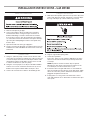
Make Gas Connection
1. Remove red cap from gas pipe.
2. Connect gas supply to dryer. Use pipe-joint compound
resistant to the action of L.P. gas for gas connections. If
flexible metal tubing is used, be certain there are no kinks.
If necessary for service, open the toe panel by removing the
2
1
⁄4" hex-head screws from the bottom of the panel. Then lift
up on the panel while pulling the bottom of the panel away
from the dryer.
3. Open the shutoff valve in the gas supply line.
4. Test all connections by brushing on an approved noncorrosive
leak-detection solution. Bubbles will show a leak. Correct any
leak found.
Connect Vent
1. Using a 4" (102 mm) clamp, connect vent to exhaust outlet
on the dryer. If connecting to existing vent, make sure the vent
is clean. The dryer vent must fit over the dryer exhaust outlet
and inside the exhaust hood. Make sure the vent is secured
to exhaust hood with a 4" (102 mm) clamp.
2. Using two or more people, move dryer to desired installation
location. Do not crush or kink vent, and remove any excess
flexible vent to improve airflow. Make sure dryer is level.
3. Check to be sure there are no kinks in the flexible gas line.
Complete Installation
1. With dryer in final position, place level on top of the dryer, first
side to side; then front to back. If the dryer is not level, adjust
the legs of the dryer up or down until the dryer is level.
2. Plug into a grounded 3 prong outlet.
3. Check dryer operation:
Insert coins. Select a cycle. Using the WHITES cycle, let the
dryer run for at least five minutes. Dryer will stop when time
is used up.
NOTE: Dryer door must be closed for dryer to operate.
When door is open, dryer stops, but timer continues to run.
To restart dryer, close door and reselect a cycle.
4. If the burner does not ignite and there is no heat inside the
dryer, shut off dryer for five minutes. Check that all gas supply
valves are in the “ON” position and that the electrical cord is
plugged in. Repeat five-minute test.
5. If drying time is too long, make sure that the lint screen is
clean and that there are no obstructions to airflow in the dryer
vent system.
WARNING
W10135154B EnFrv10.qxd:YB70809-10135134A 4/20/10 2:42 PM Page 12

13
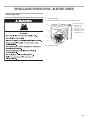
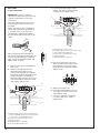
INSTALLATION INSTRUCTIONS – ELECTRIC DRYER
P
ower Supply Cord
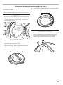
1. Disconnect power.
2. Remove the hold-down screw and terminal block cover.
3. Install strain relief.
B
D
C
A
A. Neutral ground wire
B. External ground
conductor screw
C. Center, silver-colored
terminal block screw
D. Terminal block cover
and holddown screw
W10135154B EnFrv10.qxd:YB70809-10135134A 4/20/10 2:42 PM Page 13

14
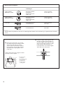
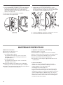
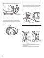
A. Strain relief tab
pointing up
B. Hole below terminal
block opening
C. Clamp section
D. Strain relief tab
pointing down
C
B
A
D
Tighten strain relief screws enough to hold the
two clamp sections together.
Power supply cord strain relief:
■ Remove the screws from a 3/4" (19 mm)
UL listed strain relief (UL marking on strain
relief). Put the tabs of the two clamp
sections into the hole below the terminal
block opening so that one tab is pointing
up and the other is pointing down, and
hold in place.
■ Put power supply cord through the strain
relief. Be sure that the wire insulation on
the power supply cord is inside the strain
relief. The strain relief should have a tight
fit with the dryer cabinet and be in a
horizontal position. Do not further tighten
strain relief screws at this point.
Electrical Connection Options
I
f your location has: And you will be Go to Section
connecting to:
4-wire receptacle A UL listed, 120/240- 4-wire connection:
(NEMA Type 14-30R) volt minimum, Power supply cord
3
0-amp, dryer power
supply cord*
3-wire receptacle A UL listed, 120/240- 3-wire connection:
(NEMA type 10-30R) volt minimum, Power supply cord
30-amp, dryer power
supply cord*
4-wire direct A fused disconnect or 4-wire connection:
circuit breaker box* Direct Wire
3-wire direct A fused disconnect or 3-wire connection:
circuit breaker box* Direct Wire
*If local codes do not permit the connection of a cabinet-ground conductor to the neutral wire, go to “Optional 3-wire connection”
section.
5"
(127 mm)
3
1
⁄2
"
(
89 mm)
W10135154B EnFrv10.qxd:YB70809-10135134A 4/20/10 2:42 PM Page 14

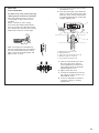
15
C
B
A
D
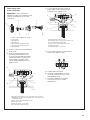
1. Remove center, silver-colored terminal
block screw.
2. Remove neutral ground wire from
external ground conductor screw.
Connect neutral ground wire and the
neutral wire (white or center wire) of
power supply cord under center,
silver-colored terminal block screw.
Tighten screw.
IMPORTANT: A 4-wire connection is
required for mobile homes and where local
c
odes do not permit the use of 3-wire
connections.
Power supply cord,
4
-wire connection:
A. 4-wire receptacle (NEMA type 14-30R)
B. 4-prong plug
C. Ground prong
D. Neutral prong
E. Spade terminals with upturned ends
F.
3/4"
(19 mm) UL listed strain relief
G. Ring terminals
A. External ground conductor screw - Dotted line shows position of
NEUTRAL ground wire before being moved to center silvercolored
terminal block screw.
B. Center, silver-colored terminal block screw
C. Neutral ground wire
D. Neutral wire (white or center wire)
E.
3/4"
(19 mm) UL listed strain relief
A. External ground conductor screw
B. Ground wire (green or bare) of power supply cord
C.
3/4"
(19 mm) UL listed strain relief
D. Center, silver-colored terminal block screw
E. Neutral ground wire
F. Neutral wire (white or center wire)
3
. Connect ground wire (green or bare) of
power supply cord to external ground
conductor screw. Tighten screw.
5. Tighten strain relief screws.
6. Insert tab of terminal block cover into
slot of dryer rear panel. Secure cover
with holddown screw.
7. You have completed your electrical
connection. Now go to “Venting
Requirements.”
4. Connect the other wires to outer terminal
block screws. Tighten screws.
E
F
G
C
B
A
D
E
F
C
B
A
D
E
W10135154B EnFrv10.qxd:YB70809-10135134A 4/20/10 2:42 PM Page 15

16
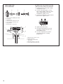
A. External ground conductor screw
B. Neutral ground wire
C. Center silver-colored terminal
block screw
D. Neutral wire (white or center wire)
E. 3/4" (19 mm) UL listed strain relief
A. 3-wire receptacle (NEMA type 10-30R)
B. 3-wire plug
C. Neutral prong
D. Spade terminals with upturned ends
E. 3/4" (19 mm) UL listed strain relief
F. Ring terminals
G. Neutral (white or center wire)
Power supply cord,
3
-wire connection:
Use where local codes permit connecting
cabinet-ground conductor to neutral wire.
1. Loosen or remove center silver-colored
terminal block screw.
2. Connect neutral wire (white or center
wire) of power supply cord to the center,
silver-colored terminal screw of the
terminal block. Tighten screw.
3. Connect the other wires to outer terminal
block screws. Tighten screws.
4. Tighten strain relief screws.
5. Insert tab of terminal block cover into
slot of dryer rear panel. Secure cover
with holddown screw.
6. You have completed your electrical
connection. Now go to “Venting
Requirements.”
C
B
A
D
E
F
G
C
B
A
D
E
W10135154B EnFrv10.qxd:YB70809-10135134A 4/20/10 2:42 PM Page 16

17
Direct Wire Method – U.S. Only
A. Removable conduit connector
B. Hole below terminal block opening
C. Strain relief threads
B
C
A
Direct wire strain relief:
■ Unscrew the removable conduit
connector and any screws from a
3/4" (19 mm) UL listed strain relief (UL
marking on strain relief). Put the threaded
section of the strain relief through the
hole below the terminal block opening.
Reaching inside the terminal block
opening, screw the removable conduit
connector onto the strain relief threads.
■ Put direct wire cable through the strain
relief. The strain relief should have a tight
fit with the dryer cabinet and be in a
horizontal position. Tighten strain relief
screw against the direct wire cable.
4. Now complete installation following
instructions for your type of electrical
connection:
4-wire (recommended)
3-wire (if 4-wire is not available)
Direct wire cable must match power supply (4-wire or 3-wire)
and be:
■ Flexible armored cable or nonmetallic sheathed copper cable
(with ground wire), protected with flexible metallic conduit.
All current-carrying wires must be insulated.
■ 10-gauge solid copper wire (do not use aluminum).
■ At least 5 ft. (1.52 m) long.
1. Disconnect power.
2. Remove hold-down screw and terminal block cover.
3. Install 3/4" conduit connector into the hole below the terminal
block opening. Connect flexible metallic conduit and tighten
connector screw. Install direct wire cable through the flexible
metallic conduit.
4. Complete installation following instructions for your type of
electrical connection:
• Four-wire (recommended method)
• Three-wire (if four-wire is not available)
B
D
C
A
A. Neutral ground wire
B. External ground
conductor screw
C. Center, silver-colored
terminal block screw
D. Terminal block cover
and holddown screw
W10135154B EnFrv10.qxd:YB70809-10135134A 4/20/10 2:42 PM Page 17

18
A. External ground conductor screw - Dotted line shows
position of NEUTRAL ground wire before being moved
to center silver-colored terminal block screw.
B. Center, silver-colored terminal block screw
C. Neutral ground wire
D. Neutral wire (white or center wire)
E. 3/4" (19 mm) UL listed strain relief
Direct Wire,
4
-wire connection:
A. External ground conductor screw
B. Ground wire (green or bare) of power supply cable
C.
3/4"
(19 mm) UL listed strain relief
D. Center, silver-colored terminal block screw
E. Neutral ground wire
F. Neutral wire (white or center wire)
When connecting to the terminal block,
place the hooked end of the wire under the
screw of the terminal block (hook facing
right), squeeze hooked end together and
tighten screw, as shown.
1. Remove center, silver-colored terminal
block screw.
2. Remove neutral ground wire from
external ground conductor screw.
Connect neutral ground wire and place
the hooked end (hook facing right) of the
neutral wire (white or center wire) of
direct wire cable under the center screw
of the terminal block. Squeeze hooked
ends together. Tighten screw.
3. Connect ground wire (green or bare)
of direct wire cable to external ground
conductor screw. Tighten screw.
4. Place the hooked ends of the other
direct wire cable wires under the outer
terminal block screws (hooks facing
right). Squeeze hooked ends together.
Tighten screws.
5. Tighten strain relief screw.
6. Insert tab of terminal block cover into
slot of dryer rear panel. Secure cover
with holddown screw.
7. You have completed your electrical
connection. Now go to “Venting
Requirements.”
IMPORTANT: A 4-wire connection is
required for mobile homes and where local
codes do not permit the use of 3-wire
connections.
Direct wire cable must have 5 ft (1.52 m)
o
f extra length so dryer can be moved
if needed.
Strip 5" (127 mm) of outer covering from
end of cable, leaving bare ground wire at
5" (127 mm). Cut 1
1
⁄2" (38 mm) from 3
remaining wires. Strip insulation back 1"
(25 mm). Shape ends of wires into a hook
shape.
C
B
A
D
E
F
C
B
A
D
E
1
"
(
2
5
m
m
)
5"
(
127
m
m
)
W10135154B EnFrv10.qxd:YB70809-10135134A 4/20/10 2:42 PM Page 18

19
Direct wire,
3-wire connection:
Use where local codes permit connecting
cabinet-ground conductor to neutral wire.
Direct wire cable must have 5 ft (1.52 m)
of extra length so dryer can be moved
if needed.
Strip 3
1
⁄2
" (89 mm) of outer covering
from end of cable. Strip insulation back 1"
(
25 mm). If using 3-wire cable with ground
wire, cut bare wire even with outer covering.
Shape ends of wires into a hook shape.
When connecting to the terminal block,
place the hooked end of the wire under the
screw of the terminal block (hook facing
right), squeeze hooked end together, and
tighten screw, as shown.
1. Loosen or remove center, silver-colored
terminal block screw.
2. Place the hooked end of the neutral wire
(white or center wire) of direct wire cable
under the center screw of terminal block
(hook facing right). Squeeze hooked end
together. Tighten screw.
A. External ground conductor screw
B. Neutral ground wire
C. Center, silver-colored terminal block screw
D. Neutral wire (white or center wire)
E. 3/4" (19 mm) UL listed strain relief
C
B
A
D
E
1
"
(2
5
m
m
)
3
1
⁄
2
"
(8
9
m
m
)
3. Place the hooked ends of the other
direct wire cable wires under the
outer terminal block screws (hooks
facing right). Squeeze hooked ends
together. Tighten screws.
4. Tighten strain relief screw.
5. Insert tab of terminal block cover into
slot of dryer rear panel. Secure cover
with holddown screw.
6. You have completed your electrical
connection. Now go to “Venting
Requirements.”
W10135154B EnFrv10.qxd:YB70809-10135134A 4/20/10 2:42 PM Page 19

20
Connect Vent
1. Using a 4" (102 mm) clamp, connect vent to exhaust outlet
in dryer. If connecting to existing vent, make sure the vent is
clean. The dryer vent must fit over the dryer exhaust outlet
and inside the exhaust hood. Make sure the vent is secured
to exhaust hood with a 4" (102 mm) clamp.
2. Move dryer into final position. Do not crush or kink vent,
and remove any excess flexible vent to improve airflow.
Make sure dryer is level.
Complete Installation
1. With dryer in final position, place level on top of the dryer, first
side to side; then front to back. If the dryer is not level, adjust
the legs of the dryer up or down until the dryer is level.
2. Plug in dryer or reconnect power.
3. Check dryer operation:
Insert coins. Select a cycle. Using the WHITES cycle, let the
dryer run for at least five minutes. Dryer will stop when time
is used up.
NOTE: Dryer door must be closed for dryer to operate.
When door is open, dryer stops, but timer continues to run.
To restart dryer, close door and reselect a cycle.
4. If drying time is too long, make sure that the lint screen is
clean, and that there are no obstacles to airflow in the dryer
vent system.
5. Now start the dryer and allow it to complete a full cycle
to make sure it is working properly.
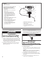
O
ptional,
3-wire connection:
U
se for direct wire or power supply cord
where local codes do not permit
connecting cabinet-ground conductor
t
o neutral wire.
1. Remove center, silver-colored terminal
block screw.
2. Remove neutral ground wire from
external ground conductor screw.
Connect neutral ground wire and the
neutral wire (white or center wire) of
power supply cord/cable under center,
silver-colored terminal block screw.
T
ighten screw.
3. Connect the other wires to outer terminal
block screws. Tighten screws.
4. Tighten strain relief screws.
5. Connect a separate copper ground wire
from the external ground conductor
screw to an adequate ground.
6. Insert tab of terminal block cover into
slot of dryer rear panel. Secure cover
with holddown screw.
C
B
A
D
E
F
A. External ground conductor screw
B. Center, silver-colored terminal block screw
C. Neutral ground wire
D. Neutral wire (white or center wire)
E. 3/4" (19 mm) UL listed strain relief
F. Grounding path determined by a qualified
electrician
WARNING
W10135154B EnFrv10.qxd:YB70809-10135134A 4/20/10 2:42 PM Page 20
La page est en cours de chargement...
La page est en cours de chargement...
La page est en cours de chargement...
La page est en cours de chargement...
La page est en cours de chargement...
La page est en cours de chargement...
La page est en cours de chargement...
La page est en cours de chargement...
La page est en cours de chargement...
La page est en cours de chargement...
La page est en cours de chargement...
La page est en cours de chargement...
La page est en cours de chargement...
La page est en cours de chargement...
La page est en cours de chargement...
La page est en cours de chargement...
La page est en cours de chargement...
La page est en cours de chargement...
La page est en cours de chargement...
La page est en cours de chargement...
La page est en cours de chargement...
La page est en cours de chargement...
La page est en cours de chargement...
La page est en cours de chargement...
La page est en cours de chargement...
La page est en cours de chargement...
La page est en cours de chargement...
La page est en cours de chargement...
-
 1
1
-
 2
2
-
 3
3
-
 4
4
-
 5
5
-
 6
6
-
 7
7
-
 8
8
-
 9
9
-
 10
10
-
 11
11
-
 12
12
-
 13
13
-
 14
14
-
 15
15
-
 16
16
-
 17
17
-
 18
18
-
 19
19
-
 20
20
-
 21
21
-
 22
22
-
 23
23
-
 24
24
-
 25
25
-
 26
26
-
 27
27
-
 28
28
-
 29
29
-
 30
30
-
 31
31
-
 32
32
-
 33
33
-
 34
34
-
 35
35
-
 36
36
-
 37
37
-
 38
38
-
 39
39
-
 40
40
-
 41
41
-
 42
42
-
 43
43
-
 44
44
-
 45
45
-
 46
46
-
 47
47
-
 48
48


Maytag MDE25PDAYW Installation Instructions Manual
- Catégorie
- Sèche-linge électriques
- Taper
- Installation Instructions Manual
- Ce manuel convient également à
dans d''autres langues
- English: Maytag MDE25PDAYW


