Hitachi DH 22PG Manuel utilisateur
- Catégorie
- Outils électroportatifs
- Taper
- Manuel utilisateur
Ce manuel convient également à

Model Rotary Hammer
Modèle Marteau rotatif
Modelo Martillo perforador
DH 22PG
MODE D’EMPLOI ET INSTRUCTIONS DE SECURITE
AVERTISSEMENT
Une utilisation incorrecte et dangereuse de cet outil motorisé peut entraîner la mort ou
de sérieuses blessures corporelles!
Ce mode d’emploi contient d’importantes informations à propos de la sécurité de ce
produit. Prière de lire et de comprendre ce mode d’emploi avant d’utiliser l’outil
motorisé. Garder ce mode d’emploi à la disponibilité des autres utilisateurs avant qu’ils
utilisent l’outil motorisé.
MANUAL DE INSTRUCCIONES E INSTRUCCIONES DE SEGURIDAD
ADVERTENCIA
¡La utilización inapropiada e insegura de esta herramienta eléctrica puede resultar en
lesiones serias o en la muerte!
Este manual contiene información importante sobre la seguridad del producto. Lea y
comprenda este manual antes de utilizar la herramienta eléctrica. Guarde este manual
para que puedan leerlo otras personas antes de que utilicen la herramienta eléctrica.
DOUBLE INSULATION
DOUBLE ISOLATION
AISLAMIENTO DOBLE
INSTRUCTION MANUAL AND SAFETY INSTRUCTIONS
WARNING
Improper and unsafe use of this power tool can result in death or serious bodily injury!
This manual contains important information about product safety. Please read and
understand this manual before operating the power tool. Please keep this manual
available for others before they use the power tool.

CONTENTS
English
Page
IMPORTANT SAFETY INFORMATION
..... 3
MEANINGS OF SIGNAL WORDS ...... 3
SAFETY ................................................................... 4
GENERAL SAFETY RULES ................. 4
SPECIFIC SAFETY RULES AND SYMBOLS
..... 5
DOUBLE INSULATION FOR SAFER
OPERATION ........................................ 6
FUNCTIONAL DESCRIPTION .............................. 7
NAME OF PARTS ................................ 7
SPECIFICATIONS ................................ 8
Page
ASSEMBLY AND OPERATION............................ 8
APPLICATIONS ................................... 8
PRIOR TO OPERATION ....................... 8
HOW TO USE .................................... 10
MAINTENANCE AND INSPECTION.................13
ACCESSORIES.....................................................14
STANDARD ACCESSORIES ............. 14
OPTIONAL ACCESSORIES ............... 15
PARTS LIST..........................................................50
TABLE DES MATIERES
Français
Page
INFORMATIONS IMPORTANTES DE SÉCURITÉ
... 18
SIGNIFICATION DES MOTS
D’AVERTISSEMENT ......................... 18
SECURITE ............................................. 19
REGLES GENERALE DE SECURITE
....... 19
REGLES DE SECURITE SPECIFIQUES ET SYMBOLES
... 20
DOUBLE ISOLATION POUR UN
FONCTIONNEMENT PLUS SUR
........ 22
DESCRIPTION FONCTIONNELLE ........ 23
NOM DES PARTIES .......................... 23
SPECIFICATIONS .............................. 23
Page
ASSEMBLAGE ET FONCTIONNEMENT ....
24
APPLICATIONS ................................. 24
AVANT L’UTILISATION .................... 24
UTILISATION ..................................... 26
ENTRETIEN ET INSPECTION ............... 29
ACCESSOIRES ...................................... 30
ACCESSOIRES STANDARD ............. 30
ACCESSOIRES SUR OPTION ........... 31
LISTA DES PIÈCES ............................... 50
ÍNDICE
Español
Página
INFORMACIÓN IMPORTANTE SOBRE SEGURIDAD
.. 34
SIGNIFICADO DE LAS PALABRAS DE
SEÑALIZACIÓN ................................. 34
SEGURIDAD ......................................... 35
NORMAS GENERALES DE SEGURIDAD
... 35
NORMAS Y SÍMBOLOS ESPECÍFICOS DE SEGURIDAD
..... 36
AISLAMIENTO DOBLE PARA OFRECER UNA
OPERACIÓN MÁS SEGURA
................... 38
DESCRIPCIÓN FUNCIONAL ................ 39
NOMENCLATURA ............................. 39
ESPECIFICACIONES .......................... 39
Página
MONTAJE Y OPERACIÓN ................... 40
APLICACIONES ................................. 40
ANTES DE LA OPERACIÓN .............. 40
COMO SE USA .................................. 42
MANTENIMIENTO E INSPECCIÓN ..... 45
ACCESORIOS ....................................... 46
ACCESORIOS ESTÁNDAR ............... 46
ACCESORIOS OPCIONALES ............ 47
LISTA DE PIEZAS ................................. 50

3
English
IMPORTANT SAFETY INFORMATION
Read and understand all of the safety precautions, warnings and operating instructions in
the Instruction Manual before operating or maintaining this power tool.
Most accidents that result from power tool operation and maintenance are caused by the
failure to observe basic safety rules or precautions. An accident can often be avoided by
recognizing a potentially hazardous situation before it occurs, and by observing appropriate
safety procedures.
Basic safety precautions are outlined in the “SAFETY” section of this Instruction Manual
and in the sections which contain the operation and maintenance instructions.
Hazards that must be avoided to prevent bodily injury or machine damage are identified by
WARNINGS on the power tool and in this Instruction Manual.
NEVER use this power tool in a manner that has not been specifically recommended by
HITACHI.
MEANINGS OF SIGNAL WORDS
WARNING indicates a potentially hazardous situations which, if ignored, could result in
death or serious injury.
CAUTION indicates a potentially hazardous situations which, if not avoided, may result in
minor or moderate injury, or may cause machine damage.
NOTE emphasizes essential information.

4
English
SAFETY
GENERAL SAFETY RULES
WARNING: Read and understand all instructions.
Failure to follow all instructions listed below, may result in electric shock,
fire and/or serious personal injury.
SAVE THESE INSTRUCTIONS
1. Work Area
(1) Keep your work area clean and well lit.
Cluttered benches and dark areas invite
accidents.
(2) Do not operate power tools in explosive
atmospheres, such as in the presence of
flammable liquids, gases, or dust. Power
tools create sparks which may ignite the
dust of fumes.
(3) Keep bystanders children, and visitors
away while operating a power tool.
Distractions can cause you to lose
control.
2. Electrical Safety
(1) Double Insulated tools are equipped with
a polarized plug (one blade is wider than
the other.) This plug will fit in a polarized
outlet only one way. If the plug does not
fit fully in the outlet, reverse the plug. If
it still does not fit, contact a qualified
electrician to install a polarized outlet.
Do not change the plug in any way.
Double Insulation
eliminates the need
for the three wire grounded power cord
and grounded power supply system.
(2) Avoid body contact with grounded
surfaces such as pipes, radiators, ranges
and refrigerators. There is an increased
risk of electric shock if your body is
grounded.
(3) Do not expose power tools to rain or wet
conditions. Water entering a power tool
will increase the risk of electric shock.
(4) Do not abuse the cord. Never use the
cord to carry the tools or pull the plug
from a receptacle. Keep cord away from
heat, oil, sharp edges or moving parts.
Replace damaged cords immediately.
Damaged cords increase the risk of
electric shock.
(5) When operating a power tool outside,
use an outdoor extension cord marked
“W-A” or “W”. These cords are rated for
outdoor use and reduce the risk of
electric shock.
3. Personal Safety
(1) Stay alert, watch what you are doing and
use common sense when operating a
power tool. Do not use tool while
tires or under the influence of drugs,
alcohol, or medication. A moment of
inattention while operating power tools
may result in serious personal injury.
(2) Dress properly. Do not wear loose
clothing or jewelry. Contain long hair.
Keep your hair, clothing and gloves away
from moving parts. Loose clothes,
jewelry, or long hair can be caught in
moving parts.
(3) Avoid accidental starting. Be sure switch
is off before plugging in. Carrying tools
with your finger on the switch or
plugging in tools that have the switch on
invites accidents.
(4) Remove adjusting keys or wrenches
before turning the tool on. A wrench or
a key that is left attached to a rotating
part of the tool may result in personal
injury.
(5) Do not overreach. Keep proper footing
and balance at all times. Proper footing
and balance enables better control of the
tool in unexpected situations.
(6) Use safety equipment. Always wear eye
protection. Dust mask, non-skid safety
shoes, hard hat, or hearing protection
must be used for appropriate conditions.

5
English
4. Tool Use and Care
(1) Use clamps or other practical way to
secure and support the workpiece to a
stable platform. Holding the work by
hand or against your body is unstable
and may lead to loss of control.
(2) Do not force tool. Use the correct tool
for your application. The correct tool will
do the job better and safer at the rate for
which it is designed.
(3) Do not use tool if switch does not turn it
on or off. Any tool that cannot be
controlled with the switch is dangerous
and must be repaired.
(4) Disconnect the plug form the power
source before making any adjustments,
changing accessories, or storing the tool.
Such preventive safety measures reduce
the risk of starting the tool accidentally.
(5) Store idle tools out of reach of children
and other untrained persons. Tools are
dangerous in the hands of untrained
users.
(6) Maintain tools with care. Keep cutting
tools sharp and clean. Properly
maintained tools, with sharp cutting
edges are less likely to bind and are
easier to control.
(7) Check for misalignment or binding of
moving parts, breakage of parts, and any
other condition that may affect the tool's
operation. If damaged, have the tool
serviced before using. Many accidents
are caused by poorly maintained tools.
(8) Use only accessories that are recommended
by the manufacturer for your model.
Accessories that may be suitable for one
tool, may become hazardous when used
with another tool.
5. Service
(1) Tool service must be performed only by
qualified repair personnel. Service or
maintenance performed by unqualified
personnel could result in a risk of injury.
(2) When servicing a tool, use only identical
replacement parts. Follow instructions
in the Maintenance section of this
manual. Use of unauthorized parts or
failure to follow Maintenance Instruction
may create a risk of electric shock or
injury.
SPECIFIC SAFETY RULES AND SYMBOLS
1. Hold tools by insulated gripping
surfaces when performing an operation
where the cutting tool may contact
hidden wiring or its own cord. Contact
with a “live” wire will make exposed
metal parts of the tool “live” and shock
the operator.
2. ALWAYS wear ear protectors when
using the tool for extended periods.
Prolonged exposure to high
intensity noise can cause hearing
loss.
3. NEVER touch the tool bit with bare
hands after operation.
4. NEVER wear gloves made from
materials likely to roll up such as cotton,
wool, cloth or string, etc.
5. ALWAYS attach the side handle and
securely grip the Rotary Hammer.
6. NEVER touch moving parts.
NEVER place your hands, fingers or
other body parts near the tool’s moving
parts.
7. NEVER operate without all guards in
place.
NEVER operate this tool without all
guards or safety features in place and
in proper working order. If maintenance
or servicing requires the removal of a
guard or safety feature, be sure to
replace the guard or safety feature
before resuming operation of the tool.
8. Use right tool.
Don’t force small tool or attachment to
do the job of a heavy-duty tool.
Don’t use tool for purpose not intended
—for example— don’t use circular saw
for cutting tree limbs or logs.
9. NEVER use a power tool for applications
other than those specified.
NEVER use a power tool for applications
other than those specified in the
Instruction Manual.
10. Handle tool correctly.
Operate the tool according to the
instructions provided herein. Do not
drop or throw the tool. NEVER allow the
tool to be operated by children,

6
English
Wipe plastic parts with a soft cloth lightly
dampened with soapy water and dry
thoroughly.
20. ALWAYS wear eye protection that meets
the requirement of the latest
revision of ANSI Standard Z87.1.
21. ALWAYS be careful with buried object
such as an underground wiring.
Touching live wiring or electric cable
with this tool may result in electric
shock.
Confirm before use whether hidden
objects are present, such as electric
cables within the wall, floor or ceiling.
22. Definitions for symbols used on this tool
V ............ volts
Hz .......... hertz
A ............ amperes
no .......... no load speed
W ........... watt
........... Class II Construction
---/min ... revolutions per minute
.......... Alternating current
DOUBLE INSULATION FOR SAFER OPERATION
To ensure safer operation of this power tool,
HITACHI has adopted a double insulation
design. “Double insulation” means that two
physically separated insulation systems
have been used to insulate the electrically
conductive materials connected to the
power supply from the outer frame handled
by the operator. Therefore, either the symbol
“
” or the words “Double insulation”
appear on the power tool or on the
nameplate.
Although this system has no external
grounding, you must still follow the normal
electrical safety precautions given in this
Instruction Manual, including not using the
power tool in wet environments.
To keep the double insulation system
effective, follow these precautions:
Only Hitachi Authorized Service Center
should disassemble or assemble this
power tool, and only genuine HITACHI
replacement parts should be installed.
individuals unfamiliar with its operation
or unauthorized personnel.
11. Keep all screws, bolts and covers tightly
in place.
Keep all screws, bolts, and plates tightly
mounted. Check their condition periodically.
12. Do not use power tools if the plastic
housing or handle is cracked.
Cracks in the tool’s housing or handle
can lead to electric shock. Such tools
should not be used until repaired.
13. Blades and accessories must be securely
mounted to the tool.
Prevent potential injuries to yourself or
others. Blades, cutting implements and
accessories which have been mounted
to the tool should be secure and tight.
14. Keep motor air vent clean.
The tool’s motor air vent must be kept
clean so that air can freely flow at all
times. Check for dust build-up frequently.
15. Operate power tools at the rated
voltage.
Operate the power tool at voltages
specified on its nameplate.
If using the power tool at a higher
voltage than the rated voltage, it will
result in abnormally fast motor
revolution and may damage the unit and
the motor may burn out.
16. NEVER use a tool which is defective or
operating abnormally.
If the tool appears to be operating
unusually, making strange noises, or
otherwise appears defective, stop using
it immediately and arrange for repairs
by a Hitachi authorized service center.
17. NEVER leave tool running unattended.
inadvertently, it may be deformed,
cracked, or damaged.Turn power off.
Don’t leave tool until it comes to a
complete stop.
18. Carefully handle power tools.
Should a power tool be dropped or
struck against hard materials
inadvertently, it may be deformed,
cracked, or damaged.
19. Do not wipe plastic parts with solvent.
Solvents such as gasoline, thinner
benzine, carbon tetrachloride, and
alcohol may damage and crack plastic
parts. Do not wipe them with such
solvents.

7
English
SAVE THESE INSTRUCTIONS
AND
MAKE THEM AVAILABLE TO
OTHER USERS
AND
OWNERS OF THIS TOOL!
FUNCTIONAL DESCRIPTION
NOTE:
The information contained in this Instruction Manual is designed to assist you in the
safe operation and maintenance of the power tool.
NEVER operate, or attempt any maintenance on the tool unless you have first read and
understood all safety instructions contained in this manual.
Some illustrations in this Instruction Manual may show details or attachments that differ
from those on your own power tool.
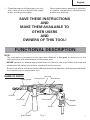
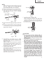
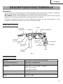
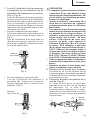
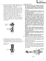
NAME OF PARTS
Clean the exterior of the power tool only
with a soft cloth moistened with soapy
water, and dry thoroughly.
Never use solvents, gasoline or thinners
on plastic components; otherwise the
plastic may dissolve.
Housing
Nameplate
Drill bit
Front cap
Grip
Depth gauge
Side handle
Push button
Switch
Change lever
Stopper
Fig. 1
Handle

8
English
SPECIFICATIONS
Motor Single-Phase, Series Commutator Motor
Power Source Single-Phase, 120V 60Hz
Current 5.4A
Capacity Concrete: 1/8" ~ 7/8" (3.4mm ~ 22mm)
Steel: 1/2" (13mm)
Wood: 15/16" (24mm)
No-Load Speed 0 – 1,500/min.
Full-load Impact Rate 0 – 6,200/min.
Weight 4.2 lbs (1.9 kg)
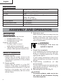
ASSEMBLY AND OPERATION
APPLICATIONS
Rotation and hammering function
Drilling anchor holes
Drilling holes in concrete
Drilling holes in tile
Rotation only function
Drilling in steel or wood.
(with optional accessories)
Tightening machine screws, wood
screws. (with optional accessories)
PRIOR TO OPERATION
1. Power source
Ensure that the power source to be
utilized conforms to the power source
requirements specified on the product
nameplate.
2. Power switch
Ensure that the switch is in the OFF
position. If the plug is connected to a
receptacle while the switch is in the ON
position, the power tool will start
operating immediately and can cause
serious injury.
3. Extension cord
When the work area is far away from the
power source, use an extension cord of
sufficient thickness and rated capacity.
The extension cord should be kept as
short as practicable.
WARNING:
Damaged cord must be
replaced or repaired.
4. Check the receptacle
If the receptacle only loosely accepts the
plug, the receptacle must be repaired.
Contact a licensed electrician to make
appropriate repairs.
If such a fautly receptacle is used, it may
cause overheating, resulting in a serious
hazard.
5. Confirming condition of the
environment:
Confirm that the work site is placed under
appropriate conditions conforming to
prescribed precautions.
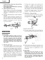
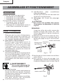
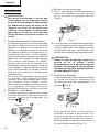
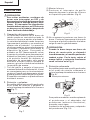
6. Mounting the drill bit (Fig. 2)
CAUTION:
To prevent accidents, make sure to turn
the switch off and disconnect the plug
from the receptacle.

9
English
Installing dust collector (B)
When using dust collector (B), insert dust
collector (B) from the tip of the bit by
aligning it to the groove on the grip (Fig. 5)
NOTE:
When using tools such as bull points, drill
bits, etc., make sure to use the genuine
parts designated by our company.
(1) Clean the shank portion of the drill bit.
(2) Insert the drill bit in a twisting manner
into the tool holder until it latches
itself. (Fig. 2)
(3) Check the latching by pulling on the drill
bit.
(4) To remove the drill bit, fully pull the grip
in the direction of the arrow and pull out
the drill bit. (Fig. 3)
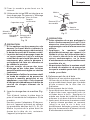
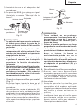
7. Installation of dust cup or dust
collector (B) (Optional accessories)
(Fig. 4, Fig. 5)
When using a rotary hammer for upward
drilling operations attach a dust cup or
dust collector (B) to collect dust or
particles for easy operation.
Installing the dust cup
Use the dust cup by attaching to the drill
bit a shown in Fig. 4.
When using a bit which has big diameter,
enlarge the center hole of the dust cup
with this rotary hammer.
Drill bit
Part of SDS-
plus shank
Grip
Front cap
Fig. 2
Grip
Fig. 3
CAUTION:
The dust cup and dust collector (B) are
for exclusive use of concrete drilling
work. Do not use them for wood or metal
drilling work.
Insert dust collector (B) completely into
the chuck part of the main unit.
When turning the rotary hammer on
while dust collector (B) is detached from
a concrete surface, dust collector (B) will
rotate together with the drill bit. Make
sure to turn on the switch after pressing
dust cup on the concrete surface. (When
using dust collector (B) attached to a drill
bit that has more than 7-15/32" (190 mm)
of overall length, dust collector (B)
cannot touch the concrete surface and
will rotate. Therefore please use dust
collector (B) by attaching to drill bits
which have 6-17/32" (166 mm), 6-19/64"
(160 mm) and 4-21/64" (110 mm) overall
length.
Dust cup
Fig. 4
Dust collector (B)
Fig. 5

10
English
Dump particles after every two or three
holes when drilling.
Please replace the drill bit after removing
dust collector (B).
8. Selecting the driver bit
Screw heads or bits will be damaged
unless a bit appropriate for the screw
diameter is employed to drive in the
screws.
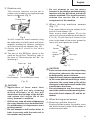
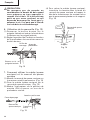
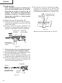
9. Confirm the direction of bit rotation
(Fig. 6)
The bit rotates clockwise (viewed from
the rear side) by pushing the R-side of
the push button. The L-side of the push
button is pushed to turn the bit
counterclockwise.
HOW TO USE
CAUTION:
To prevent accidents, make sure to turn
the switch off and disconnect the plug
from the receptacle when the drill pits
and other various parts are installed or
removed. The power switch should also
be turned off during a work break and
after work.
1. Switch operation
The rotation speed of the drill bit can be
controlled steplessly by varying the
amount that the trigger switch is pulled.
Speed is low when the trigger switch is
pulled slightly and increases as the
switch is pulled more. To turn the switch
OFF, release the trigger switch to its
original position. However, the switch
trigger can only be pulled in halfway
during reverse and rotates at half the
speed of forward operation.
Pulling the trigger and pushing the
stopper, it keeps the switched-on
condition which is convenient for
continuous running. When switching off,
the stopper can be disconnected by
pulling the trigger again. The switch
stopper is unusable during reverse.
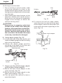
2. Rotation + Hammering
This rotary hammer can be set to rotation
and hammering mode by turning the
change lever to the
mark (Fig.7)
(1) Mount the drill bit.
(2) Pull the trigger switch after applying the
drill bit tip to the drilling position (Fig. 8)
(3) Pushing the rotary hammer forcibly is not
necessary at all. Pushing slightly so that
drill dust comes out gradually is just
sufficient.
CAUTION:
When the drill bit touches an iron
reinforcing rod, the bit will stop
immediately and the rotary hammer will
react to revolve. Therefore please grip
the side handle and handle tightly as
shown in Fig. 8.
Push
button
R
L
L
R
R
L
Fig. 6
Fig. 7
Change lever
Fig. 8

11
English
3. Rotation only
This rotation hammer can be set to
rotation only mode by turning the change
lever to the
mark (Fig. 9)
To drill a wood or metal material using
the separately sold drill chuck and chuck
adaptor, proceed as follows. Installing
drill chuck and chuck adaptor (Fig. 10):
(1) Attach the drill chuck to the chuck
adaptor.
(2) The part of the SDS-plus shank is the
same as the drill bit. Therefore, refer to
the item of “Mounting the drill bit” for
attaching it.
CAUTION:
Application of force more than
necessary will not only reducing
drilling efficiency at all, but will
deteriorate the tip edge of the drill bit
and reduce the service life of the
rotary hammer in addition.
Drill bit may snap off while withdrawing
the rotary hammer from the drilled hole.
For withdrawing, it is important to use a
pushing motion.
Do not attempt to drill anchor holes or
holes in concrete with the main unit in
the rotation only function.
Do not attempt to use the rotary
hammer in the rotation and hammering
function with the drill chuck and chuck
adaptor attached. This would seriously
shorten the service life of every
components of the machine.
4. When driving machine screws
(Fig. 11)
First, insert the bit into the socket in the
end of chuck adaptor (D).
Next, mount chuck adaptor (D) on the
main unit using procedures described in
6 (1), (2), (3), put the tip of the bit in the
slots in the head of the screw, grasp the
main unit and tighten the screw.
CAUTION:
Exercise care not to excessively prolong
driving time, otherwise, the screws may
be damaged by excessive force.
Apply the rotary hammer perpendicularly
to the screw head when driving a screw;
otherwise, the screw head or bit will be
damaged, or driving force will not be fully
transferred to the screw.
Do not attempt to use the rotary ham-
mer in the rotation and hammering func-
tion with chuck adaptor (D) and bit at-
tached.
5. When driving wood screws
(1) Selecting a suitable driver bit
Employ phillips screws, if possible, since
the driver bit easily slips off the heads of
slotted-head screws.
Drill bit
Part of SDS-plus shank
Grip
Front cap
Chuck adapter
Fig. 10
Fig. 9
Change lever
Bit
Socket
Chuck
adapter
(D)
Front cap
Grip
Fig. 11

12
English
(2) Driving in wood screws
Prior to driving in wood screws, make
pilot holes suitable for them in the
wooden board. Apply the bit to the screw
head grooves and gently drive the screws
into the holes.
After rotating the rotary hammer at low
speed for a while until a wood screw in
partly driven into the wood, squeeze the
trigger more strongly to obtain the
optimum driving force.
CAUTION:
Exercise care in preparing a pilot hole
suitable for the wood screw taking the
hardness of the wood into consideration.
Should the hole be excessively small or
shallow, requiring much power to drive
the screw into it, the thread of the wood
screw may sometimes be damaged.
6. Using depth gauge (Fig. 12)
(1) Loosen the knob on the side handle, and
insert the depth gauge into the mounting
hole on the side handle.
(2) Adjust the depth gauge position
according to the depth of the hole and
tighten the knob bolt securely.
7. How to use the drill bit (taper shank)
and the taper shank adaptor.
(1) Mount the taper shank adaptor to the
rotary hammer. (Fig. 13)
(2) Mount the drill bit (taper shank) to the
taper shank adaptor. (Fig. 13)
(3) Turn the switch ON, and drill a hole in
prescribed depth.
(4) To remove the drill bit (taper shank),
insert the cotter into the slot of the taper
shank adaptor and strike the head of the
cotter with a hammer supporting on the
rests. (Fig. 14)
Mounting hole
Depth gauge
Knob on side
handle
Fig. 12
Front cap
Grip
Taper shank
adaptor
Drill bit
Fig. 13
Cotter
Rests
Taper shank adaptor
Fig. 14

13
English
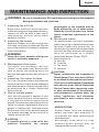
MAINTENANCE AND INSPECTION
WARNING: Be sure to switch power OFF and disconnect the plug from the receptacle
during maintenance and inspection.
1. Inspecting the drill bits
Since use of a dull tool will cause motor
malfunctioning and degraded efficiency,
replace the drill bit with a new one or
resharpening without delay when
abrasion is noted.
2. Inspecting the screws
Regularly inspect all screws and ensure
that they are properly tightened. Should
any of the screws be loosened, retighten
them immediately.
WARNING:
Using this rotary hammer with loosen
screws is extremely dangerous.
3. Maintenance of the motor
The motor unit winding is the very
“heart” of the power tool. Exercise due
care to ensure the winding does not
become damaged and/or wet with oil or
water.
4. Inspecting the carbon brushes
For your continued safety and electrical
shock protection, carbon brush inspection
and replacement on this tool should ONLY
be performed by a Hitachi Authorized
Service Center.
5. How to replace grease
Low viscosity grease is applied to this
rotary hammer so that it can be used for
a long period without replacing the
grease. Please contact the nearest service
center for grease replacement when any
grease is leaking from loosened screw.
Further use of the rotary hammer despite
the grease shortage causes seizure to
reduce the service life.
CAUTION:
A specific grease is used with this
machine, therefore, the normal
performance of the machine may be
badly affected by use of other grease.
Please be sure to let one of our service
agents undertake replacement of the
grease.
6. Service and repairs
All quality power tools will eventually
require servicing or replacement of parts
because of wear from normal use. To
assure that only authorized replacement
parts will be used, all service and repairs
must be performed by a Hitachi
Authorized Service Center, ONLY.
7. Service parts list
A: Item No.
B: Code No.
C: No. Used
D: Remarks
CAUTION:
Repair, modification and inspection of
Hitachi Power Tools must be carried out
by an Hitachi Authorized Service Center.
This Parts List will be helpful if presented
with the tool to the Hitachi Authorized
Service Center when requesting repair
or other maintenance. In the operation
and maintenance of power tools, the
safety regulations and standards
prescribed in each country must be
observed.
MODIFICATIONS:
Hitachi Power Tools are constantly
being improved and modified to
incorporate the latest technological
advancements.
Accordingly, some parts (i.e. code
numbers and/or design) may be
changed without prior notice.

14
English
ACCESSORIES
WARNING: ALWAYS use Only authorized HITACHI replacement parts and
accessories. NEVER use replacement parts or accessories which are
not intended for use with this tool. Contact HITACHI if you are not sure
whether it is safe to use a particular replacement part or accessory
with your tool.
The use of any other attachment or accessory can be dangerous and
could cause injury or mechanical damage.
NOTE:
Accessories are subject to change without any obligation on the part of the HITACHI.
STANDARD ACCESSORIES
(1) Plastic Case (Code No. 327883) .......................................................................................... 1
(2) Side Handle (Code No. 324548).......................................................................................... 1
(3) Depth Gauge (Code No. 310331) ........................................................................................ 1

15
English
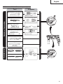
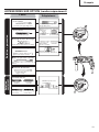
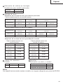
OPTIONAL ACCESSORIES (sold separately)
Adapter for slender shaft
(SDS-plus shank)
Drill bit (Slender shaft)
Drilling holes in concrete or tile
+
Drill bit (Taper shank)
Taper shank
adapter
Cotter
Drilling holes in concrete
Anchor setting
Anchor setting adapter
+ +
Chuck
adapter
Drill chuck
(13 VLRB-D)
Special
screw
Demolishing operation
Dust cup
Dust collector (B)
Rotation + Hammering
Drilling holes in concrete or tile
Drilling anchor holes
Driving screws
Drilling in steel or wood
, Driver bit - Driver bit
Drill bit for steel Drill bit for
wood
Bull point
(Round type)
Drill bit
Tool Adapters
Use on jobs facing upwards
Rotation only
( )
Straight shank bit for
impact drill
13 mm Rotary hammer chuck
(SDS-plus shank)

16
English
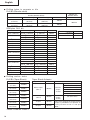
Drilling holes in concrete or tile
Drill Bit (Slender shaft)
Drilling anchor holes
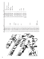
Drill Bit (Taper Shank) Taper Shank Adaptor
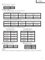
Outer dia. Overall length Effective length Code No.
5/32
"
(4.0 mm) 4-5/16
"
(110 mm) 2
"
(50 mm) 303571
3/16
"
(5.0 mm)
4-5/16
"
(110 mm) 2
"
(250 mm) 303575
6-5/16
"
(160 mm) 4
"
(100 mm) 303578
7/32
"
(5.5 mm) 4-5/16
"
(110 mm) 2
"
(50 mm) 303576
1/4
"
(6.5 mm) 6-5/16
"
(160 mm) 4
"
(100 mm) 303581
9/32
"
(7.0 mm) 6-5/16
"
(160 mm) 4
"
(100 mm) 303582
5/16
"
(8.0 mm) 6-5/16
"
(160 mm) 4
"
(100 mm) 303584
11/32
"
(8.5 mm) 6-5/16
"
(160 mm) 4
"
(100 mm) 303585
3/8
"
(9.0 mm) 6-5/16
"
(160 mm) 4
"
(100 mm) 303586
15/32
"
(12.0 mm)
6-1/2
"
(166 mm) 4
"
(100 mm) 303591
10-1/4
"
(260 mm) 7-7/8
"
(200 mm) 303606
1/2
"
(12.7 mm) 6-1/2
"
(166 mm) 4
"
(100 mm) 303593
9/16
"
(14.0 mm) 6-1/2
"
(166 mm) 4
"
(100 mm) 303595
19/32
"
(15.0 mm) 6-1/2
"
(166 mm) 4
"
(100 mm) 303598
5/8
"
(16.0 mm)
6-1/2
"
(166 mm) 4
"
(100 mm) 303599
10-1/4
"
(260 mm) 7-7/8
"
(200 mm) 303611
21/32
"
(17.0 mm) 6-1/2
"
(166 mm) 4
"
(100 mm) 303601
3/4
"
(19.0 mm) 10-1/4
"
(260 mm) 7-7/8
"
(200 mm) 303613
3/4
"
(20.0 mm) 10
"
(250 mm) 7-7/8
"
(200 mm) 303614
7/8
"
(22.0 mm) 10
"
(250 mm) 7-7/8
"
(200 mm) 303615
Drill Bit (Slender Shaft)
Adaptor for
Slender Shaft
Outer dia. Effective Length Overall Length Code No. Code No.
1/8" 1-25/32" 3-35/64"
306369
(3.4 mm) (45 mm) (90 mm)
306370
9/64" 1-25/32" 3-35/64"
306368
(3.5 mm) (45 mm) (90 mm)
SDS-plus Drill bit
Code No.
Dust cup 971787
Dust collector (B) 306885
Cotter: Code No. 944477
External dia. Code No.
7/16"
944460
(11 mm)
1/2"
944461
(12.3 mm)
1/2"
993038
(12.7 mm)
9/16"
944462
(14.3 mm)
9/16"
944500
(14.5 mm)
11/16"
944463
(17.5 mm)
7/8"
944464
(21.5 mm)
Taper mode Code No. Applicable drill bit
7/16" (11 mm)
1/2" (12.3 mm)
303617
1/2" (12.7 mm)
9/16" (14.3 mm)
9/16" (14.5 mm)
11/16" (17.5 mm)
303618 7/8" (21.5 mm)
A-taper 303619
B-taper 303620
Morse taper
(No. 1)
Drill bit
(Taper
shank)
Taper shank adaptor formed A-taper or
B-taper is provided as an optional ac-
cessory, but drill bit for it is not pro-
vided.
Morse taper
(No. 2)
Drill bit
(Taper
shank)

17
English
Drilling holes in concrete
Rotary hammer chuck
<Inner wedge type with
the headless screw>
Anchor size Code No.
W1/4"
971799
(6.3 mm)
W5/16"
971800
(8 mm)
W3/8"
971801
(9.5 mm)
W1/2"
971802
(12.7 mm)
W5/8"
971803
(15.9 mm)
Anchor setting
Anchor setting adaptor (for Rotary hammer)
<Outer wedge type with the female screw>
Anchor size
W 1/4" W 5/16" W 3/8"
(6.3 mm) (8 mm) (9.5 mm)
Overall Length
10-1/4" 10-1/4" 6-1/4" 10-1/4"
(260 mm) (260 mm) (160 mm) (260 mm)
Code No. 302976 302975 303621 302974
<Inner wedge type with the headless screw>
A
nchor size
W 1/4" W 5/16" W 3/8"
(6.3 mm) (8 mm) (9.5 mm)
Overall Length
10-1/4" 10-1/4" 6-1/4" 10-1/4"
(260 mm) (260 mm) (160 mm) (260 mm)
Code No. 302979 302978 303622 302977
Anchor setting adaptor (for Manual hammer)
<Outer wedge type with
the female screw>
Anchor size Code No.
W1/4"
971794
(6.3 mm)
W5/16"
971795
(8 mm)
W3/8"
971796
(9.5 mm)
W1/2"
971797
(12.7 mm)
W5/8"
971798
(15.9 mm)
Capacity Code No.
2.5-13mm 303332
Driving screws
Drilling in steel or wood
Demolishing operation
Bull point
NOTE:
Specifications are subject to change without any obligation on the part of the HITACHI.
Type Overall length Code No.
Round 10" (250 mm) 303046
Special screw 981122
Drill chuck 321814
Chuck adaptor 303623

18
Français
INFORMATIONS IMPORTANTES DE SÉCURITÉ
Lire et comprendre toutes les précautions de sécurité, les avertissements et les instructions
de fonctionnement dans ce mode d’emploi avant d’utiliser ou d’entretenir cet outil motorisé.
La plupart des accidents causés lors de l’utilisation ou de l’entretien de l’outil motorisé
proviennent d’un non respect des règles ou précautions de base de sécurité. Un accident
peut la plupart du temps être évité si l’on reconnaît une situation de danger potentiel avant
qu’elle ne se produise, et en observant les procédures de sécurité appropriées.
Les précautions de base de sécurité sont mises en évidence dans la section “SECURITE” de
ce mode d’emploi et dans les sections qui contiennent les instructions de fonctionnement
et d’entretien.
Les dangers qui doivent être évités pour prévenir des blessures corporelles ou un
endommagement de la machine sont identifiés par AVERTISSEMENTS sur l’outil motorisé
et dans ce mode d’emploi.
NE JAMAIS utiliser cet outil motorisé d’une manière qui n’est pas spécifiquement
recommandée par HITACHI.
SIGNIFICATION DES MOTS D’AVERTISSEMENT
AVERTISSEMENT indique des situations potentiellement dangereuses qui, si elles sont
ignorées, pourraient entraîner la mort ou de sérieuses blessures.
PRECAUTION indique des situations dangereuses potentilles qui, si elles ne sont pas
évitées, peuvent entraîner de mineures et légères blessures ou endommager la machine.
REMARQUE met en relief des informations essentielles.

19
Français
SECURITE
REGLES GENERALE DE SECURITE
AVERTISSEMENT: Lire et coxmprendre toutes les instructions.
Un non respect de toutes les instructions ci-dessous peut
entraîner une électrocution, un incendie et/ou de sérieuses
blessures personnelles.
CONSERVER CES INSTRUCTIONS
1. Zone de travail
(1) Garder la zone de travail propre et bien
éclairée. Les établis mal rangés et les
zones sombres invitent aux accidents.
(2) Ne pas utiliser les outils motorisés dans
une atmosphère explosive, telle qu’en
présence de liquides inflammables, de
gaz ou de poussières. Les outils
motorisés créent des étincelles qui
risquent d’enflammer la poussière ou les
vapeurs.
(3) Tenir les spectateurs, les enfants et les
visiteurs éloignés, lors de l’utilisation de
l’outil motorisé. Une distraction peut
faire perdre le contrôle de la machine.
2. Sécurité électrique
(1) Les outils à double isolation sont équipés
d’une fiche polarisée (une lame est plus
large que l’autre). Cette fiche ne
pénétrera dans une prise secteur
polarisée que dans un sens. Si la fiche
ne rentre pas complètement dans la
prise, la retourner. Si elle ne rentre
toujours pas, contacter un électricien
qualifié pour installer une prise polarisée.
Ne pas modifier la fiche d’aucune façon.
La double isolation
élimine le besoin
d’un cordon d’alimentation à trois fils et
d’un système d’alimentation avec mises
à la terre.
(2) Eviter tout contact corporel avec les sur-
faces mises à la terre telles que les
canalisations, les radiateurs, les
réchauds et les réfrigérateurs. Il y a un
risque accru d’électrocution si son corps
est mis à la terre.
(3) Ne pas exposer les outils motorisés à la
pluie ou à l’humidité. De l’eau pénétrant
à l’intérieur de l’outil motorisé augmente
le risque d’électrocution.
(4) Ne pas maltraiter le cordon
d’alimentation. Ne jamais utiliser le cor-
don pour porter les outils ou tirer sur la
fiche du réceptacle. Garder le cordon à
l’écart de la chaleur, de l’huile, des arêtes
coupantes ou des pièces en mouvement.
Remplacer les cordons endommagés
immédiatement. Des cordons
endommagés augmentent le risque
d’électrocution.
(5) Lors de l’utilisation d’un outil motorisé,
utiliser un cordon de rallonge extérieur
marqué “W-A” ou “W”. Ces cordons
sont prévus pour une utilisation
extérieure et réduisent les risques
d’électrocution.
3. Sécurité personnelle
(1) Rester sur ses gardes, regarder ce que
l’on fait et utiliser son sens commun lors
de l’utilisation d’un outil motorisé. Ne
pas utiliser un outil en état de fatigue
ou sous l’influence de drogues, d’alcool
ou de médicaments. Un moment
d’inattention lors de l’utilisation de l’outil
motorisé peut entraîner de sérieuses
blessures personnelles.
(2) S’habiller correctement. Ne pas porter
des vêtements larges ou des bijoux.
Attacher les cheveux longs. Tenir ses
cheveux, vêtements et ses gants
éloignés des parties mobiles. Les
vêtements larges, les bijoux et les
cheveux longs peuvent se prendre dans
les parties mobiles.

20
Français
(3) Eviter tout démarrage accidentel.
S’assurer que le l’interrupteur
d’alimentation est sur la position d’arrêt
avant de brancher la machine. Trans-
porter l’appareil avec les doigts sur
l’interrupteur d’alimentation ou brancher
un outil avec l’interrupteur sur la posi-
tion marche invite aux accidents.
(4) Retirer les clefs d’ajustement ou les
commutateurs avant de mettre l’outil
sous tension. Une clef qui est laissée
attachée à une partie tournante de l’outil
peut provoquer une blessure
personnelle.
(5) Ne pas trop présumer de ses forces.
Garder en permanence une position et
un équilibre correct. Une position et un
équilibre correct permettent un meilleur
contrôle de l’outil dans des situations
inattendues.
(6) Utiliser un équipement de sécurité.
Toujours porter une protection pour les
yeux. Utiliser un masque à poussière, des
chaussures de sécurité antidérapantes,
un casque dur et une protection pour les
oreilles dans les conditions appropriées.
4. Utilisation de l’outil et entretien
(1) Utiliser un étau ou toutes autres façons
de fixer et maintenir la pièce à usiner sur
une plate-forme stable. Tenir la pièce
avec la main ou contre son corps est in-
stable et peut conduire à une perte de
contrôle de l’outil.
(2) Ne pas forcer sur l’outil. Utiliser l’outil
correct pour l’application souhaitée.
L’outil correct réalisera un meilleur et
plus sûr travail dans le domaine pour
lequel il a été conçu.
(3) Ne pas utiliser un outil s’il ne se met pas
sous ou hors tension avec un
interrupteur. Un outil qui ne peut pas être
commandé avec un interrupteur est
dangereux et doit être réparé.
(4) Déconnecter la fiche de la source
d’alimentation avant de réaliser tout
ajustement, changement d’accessoires
ou pour ranger l’outil. De telles mesures
de sécurité réduisent le risque que l’outil
ne démarre accidentellement.
(5) Ranger les outils inutilisés hors de la
portée des enfants et des autres
personnes inexpérimentées. Les outils
sont dangereux dans les mains de
personnes inexpérimentées.
(6) Utiliser un équipement de sécurité.
Toujours porter des lunettes de protec-
tion. Utiliser un masque à poussière, des
chaussures de sécurité antidérapantes,
un couvre-chef dur ou des protections de
l’ouïe dans les conditions appropriées.
(7) Vérifier les défauts d’alignement ou
grippage des parties mobiles, les rup-
tures des pièces et toutes les autres con-
ditions qui peuvent affecter le
fonctionnement des outils. En cas de
dommage, faire réparer l’outil avant de
l’utiliser. Beaucoup d’accidents sont
causés par des outils mal entretenus.
(8) Utiliser uniquement les accessoires
recommandés par le fabricant pur le
modèle utilisé. Des accessoires qui
peuvent convenir à un outil, peuvent
devenir dangereux lorsqu’ils sont utilisés
avec un autre outil.
5. Réparation
(1) La réparation de l’outil ne doit être
réalisée uniquement par un réparateur
qualifié. Une réparation ou un entretien
réalisé par un personnel non qualifié peut
entraîner des risques de blessures.
(2) Lors de la réparation d’un outil, utiliser
uniquement des pièces de rechange
identiques. Suivre les instructions de la
section d’entretien de ce mode d’emploi.
L’utilisation de pièces non autorisées ou
un non respect des instructions
d’entretien peut créer un risque
d’électrocution ou de blessures.
REGLES DE SECURITE SPECIFIQUES ET SYMBOLES
1. Tenir les outils par les surfaces de
grippage lors de la réalisation
d’opération où l’outil de coupe risque
d’entrer en contact avec des câbles
cachés ou son propre cordon. Un con-
tact avec un fil “sous tension” mettra les
parties métalliques de l’outil “sous ten-
sion” et électrocutera l’utilisateur.
2. TOUJOURS porter des protections
d’oreille lors de l’utilisation de l’outil
pendant de longues périodes.
La page est en cours de chargement...
La page est en cours de chargement...
La page est en cours de chargement...
La page est en cours de chargement...
La page est en cours de chargement...
La page est en cours de chargement...
La page est en cours de chargement...
La page est en cours de chargement...
La page est en cours de chargement...
La page est en cours de chargement...
La page est en cours de chargement...
La page est en cours de chargement...
La page est en cours de chargement...
La page est en cours de chargement...
La page est en cours de chargement...
La page est en cours de chargement...
La page est en cours de chargement...
La page est en cours de chargement...
La page est en cours de chargement...
La page est en cours de chargement...
La page est en cours de chargement...
La page est en cours de chargement...
La page est en cours de chargement...
La page est en cours de chargement...
La page est en cours de chargement...
La page est en cours de chargement...
La page est en cours de chargement...
La page est en cours de chargement...
La page est en cours de chargement...
La page est en cours de chargement...
La page est en cours de chargement...
La page est en cours de chargement...
-
 1
1
-
 2
2
-
 3
3
-
 4
4
-
 5
5
-
 6
6
-
 7
7
-
 8
8
-
 9
9
-
 10
10
-
 11
11
-
 12
12
-
 13
13
-
 14
14
-
 15
15
-
 16
16
-
 17
17
-
 18
18
-
 19
19
-
 20
20
-
 21
21
-
 22
22
-
 23
23
-
 24
24
-
 25
25
-
 26
26
-
 27
27
-
 28
28
-
 29
29
-
 30
30
-
 31
31
-
 32
32
-
 33
33
-
 34
34
-
 35
35
-
 36
36
-
 37
37
-
 38
38
-
 39
39
-
 40
40
-
 41
41
-
 42
42
-
 43
43
-
 44
44
-
 45
45
-
 46
46
-
 47
47
-
 48
48
-
 49
49
-
 50
50
-
 51
51
-
 52
52


Hitachi DH 22PG Manuel utilisateur
- Catégorie
- Outils électroportatifs
- Taper
- Manuel utilisateur
- Ce manuel convient également à
dans d''autres langues
- English: Hitachi DH 22PG User manual
- español: Hitachi DH 22PG Manual de usuario