ELICA EGL430S1 Guide d'installation
- Catégorie
- Hottes
- Taper
- Guide d'installation
Ce manuel convient également à

Use, Care, and Installation Guide
Guide d’utilisation, d’entretien et d’installation
Guía de instalación, uso y mantenimiento
READ AND SAVE THESE INSTRUCTIONS
LISEZ CES INSTRUCTIONS ET CONSERVEZ-LES
LEA Y GUARDE ESTAS INSTRUCCIONES

English
Contents page 3
French
Sommaire page 19
Spanish
Contenido página 35

3
English
Contents
Important safety Notice ................................................................................................ 4
Electrical & Installation requirements......................................................................... 6
Electrical requirements.................................................................................................................................6
Before installing the hood.............................................................................................................................7
List of Materials............................................................................................................. 8
Parts supplied...............................................................................................................................................8
Parts not supplied.........................................................................................................................................8
Dimensions and Clearances ........................................................................................ 9
Ducting Options and Examples................................................................................. 10
Venting methods ........................................................................................................................................10
Preparation.................................................................................................................................................11
Installation ................................................................................................................... 12
Installation - Ducting version ......................................................................................................................12
Description of the hood & Controls .......................................................................... 16
Controls ......................................................................................................................................................16
User Servicing and Maintenance Instructions......................................................... 18
Cleaning .....................................................................................................................................................18
Grease Filter...............................................................................................................................................18
Replacing the light bulb..............................................................................................................................18
APPROVED FOR RESIDENTIAL APPLIANCES
FOR RESIDENTIAL USE ONLY
READ AND SAVE THESE INSTRUCTIONS
PLEASE READ ENTIRE INSTRUCTIONS BEFORE PROCEEDING.
INSTALLATION MUST COMPLY WITH ALL LOCAL CODES.
IMPORTANT: Save these Instructions for the Local Electrical Inspector’s use.
INSTALLER: Please leave these Instructions with this unit for the owner.
OWNER: Please retain these instructions for future reference.
Safety Warning: Turn off power circuit at service panel and lock out panel,
before wiring this appliance.
Requirement: 120 V AC, 60 Hz. 15 or 20 A Branch Circuit

4
READ AND SAVE THESE INSTRUCTIONS
Important safety Notice
CAUTION
FOR GENERAL VENTILATING USE ONLY.
DO NOT
USE TO EXHAUST HAZARDOUS
OR EXPLOSIVE MATERIALS OR VA-
POURS.
WARNING
TO REDUCE THE RISK OF FIRE,
ELECTRIC SHOCK, OR INJURY TO
PERSONS, OBSERVE THE FOLLOWING:
A. Use this unit only in the manner intended
by the manufacturer. If you have questions,
contact the manufacturer.
B. Before servicing or cleaning the unit,
switch power off at service panel and lock
service panel disconnecting means to
prevent power from being switched on
accidentally. When the service
disconnecting means cannot be locked,
securely fasten a prominent warning
device, such as a tag, to the service
panel.
C. Installation Work and Electrical Wiring
Must Be Done By Qualified Person(s) In
Accordance With All Applicable Codes &
Standards, Including Fire-rated
Construction.
D. Sufficient air is needed for proper
combustion and exhausting of gases
through the flue (Chimney) of fuel burning
equipment to prevent back- drafting.
Follow the heating equipment
manufacturers guideline and safety
standards such as those published by the
National Fire Protection Association
(NFPA), the American Society for
Heating, Refrigeration and Air
Conditioning Engineers (ASHRAE), and
the local code authorities.
E. When cutting or drilling into wall or
ceiling, do not damage electrical wiring
and other hidden utilities.
F. Ducted systems must always be vented
to the outdoors.
CAUTION
To reduce risk of fire and to properly
exhaust air, be sure to duct air outside -
do not vent exhaust air into spaces within
walls, ceilings, attics, crawl spaces, or
garages.
WARNING
TO REDUCE THE RISK OF FIRE, USE
ONLY METAL DUCT WORK.
Install this hood in accordance with all
requirements specified.
WARNING
To Reduce The Risk Of Fire Or Electric
Shock, Do Not Use This Hood With Any
External Solid State Speed Control
Device.
WARNING
TO REDUCE THE RISK OF A RANGE TOP
GREASE FIRE.
a) Never leave surface units unattended at
high settings. Boilovers cause smoking
and greasy spillovers that may ignite.
Heat oils slowly on low or medium
settings.
b) Always turn hood ON when cooking at
high heat or when flambeing food (I.e.
Crepes Suzette, Cherries Jubilee,
Peppercorn Beef Flambe’).
c) Clean ventilating fans frequently. Grease
should not be allowed to accumulate on
fan or filter.
d) Use proper pan size. Always use
cookware appropriate for the size of the
surface element.

5
WARNING
TO REDUCE THE RISK OF INJURY TO
PERSONS, IN THE EVENT OF A RANGE
TOP GREASE FIRE, OBSERVE THE
FOLLOWING
a
:
a) SMOTHER FLAMES with a close-fitting
lid, cookie sheet, or other metal tray, then
turn off the gas burner or the electric
element. BE CAREFUL TO PREVENT
BURNS. If the flames do not go out
immediately, EVACUATE AND CALL
THE FIRE DEPARTMENT.
b) NEVER PICK UP A FLAMING PAN - you
may be burned.
c) DO NOT USE WATER, including wet
dishcloths or towels - a violent steam
explosion will result.
d) Use an extinguisher ONLY if:
1) You know you have a class ABC
extinguisher, and you already know how to
operate it.
2) The fire is small and contained in
the area where it started.
3) The fire department is being
called.
4) You can fight the fire with your
back to an exit.
a
Based on "Kitchen Firesafety Tips"
published by NFPA.
OPERATION
a. Always leave safety grills and filters in
place. Without these components, operating
blowers could catch onto hair, fingers and
loose clothing.
The manufacturer declines all responsibility
in the event of failure to observe the
instructions given here for installation,
maintenance and suitable use of the product.
The manufacturer further declines all
responsibility for injury due to negligence and
the warranty of the unit automatically expires
due to improper maintenance.

6
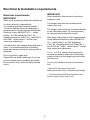
Electrical & Installation requirements
Electrical requirements
IMPORTANT
Observe all governing codes and ordinances.
It is the customer’s responsibility:
To contact a qualified electrical installer.
To assure that the electrical installation is
adequate and in conformance with National
Electrical Code, ANSI/NFPA 70 — latest
edition*, or CSA Standards C22.1-94,
Canadian Electrical Code, Part 1 and C22.2
No.0-M91 - latest edition** and all local
codes and ordinances.
If codes permit and a separate ground wire is
used, it is recommended that a qualified
electrician determine that the ground path is
adequate.
Do not ground to a gas pipe.
Check with a qualified electrician if you are
not sure range hood is properly grounded.
Do not have a fuse in the neutral or ground
circuit.
IMPORTANT
Save Installation Instructions for electrical
inspector’s use.
The range hood must be connected with
copper wire only.
The range hood should be connected directly
to the fused disconnect (Or circuit breaker)
box through metal electrical conduit.
Wire sizes must conform to the requirements
of the National Electrical Code ANSI/NFPA
70 — latest edition*, or CSA Standards
C22.1-94, Canadian Electrical Code Part 1
and C22.2 No. 0-M91 - latest edition** and all
local codes and ordinances.
A U.L.- or C.S.A.-listed conduit connector
must be provided at each end of the power
supply conduit (at the range hood and at the
junction box).
Copies of the standards listed may be obtained
from:
* National Fire Protection Association
Batterymarch Park Quincy, Massachusetts 02269
** CSA International 8501 East Pleasant Valley
Road Cleveland, Ohio 44131-5575

7
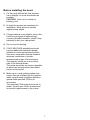
Before installing the hood
1. For the most efficient air flow exhaust,
use a straight run or as few elbows as
possible.
CAUTION: Vent unit to outside of
building, only.
2. At least two people are necessary for
installation. Wear gloves to protect
against sharp edges.
3. Fittings material is provided to secure the
hood to most types of walls/ceilings,
consult a Qualified Installer, check if they
perfectly fit with your cabinet/wall.
4. Do not use flex ducting.
5. COLD WEATHER installations should
have an additional backdraft damper
installed to minimize backward cold air
flow and a nonmetallic thermal break to
minimize conduction of outside
temperatures as part of the ductwork.
The damper should be on the cold air
side of the thermal break.
The break should be as close as possible
to where the ducting enters the heated
portion of the house.
6. Make up air: Local building codes may
require the use of Make-Up Air Systems
when using Ducted Ventilation Systems
greater than specified CFM of air
movement.
The specified CFM varies from locale to
locale. Consult your HVAC professional
for specific requirements in your area.

8
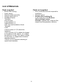
List of Materials
Parts supplied
• Blower unit housing
• Hood canopy
• Stainless steel mesh filter
• Halogen light bulb x 2
• Hardware Packet:
Transition
Allen Wrench
Lower bracket x 2
Upper Bracket x 2
Use, Care and Installation Guide
Template
Cloth
2,9x9,5 screws x 2 (To attach the
transition)
4,5x16 screws x 4 (2 to attach the drawer
to the bottom of the cabinet + 2 to attach
the deflector on top of the cabinet ceiling)
5x18 screws x 4 (Upper/lower brackets
adjusting screws)
3,5x9,5 x 4 (For definitive attaching of
upper/lower brackets).
Parts not supplied
• Duct, conduit and all tools required for
installation.
• Remote Control
• Ductless Recirculating Kit
To be used only in the Ductless
(Recirculating) version
includes: charcoal filter, charcoal filter
support and fixing bracket, deflector

9
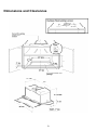
Dimensions and Clearances

10
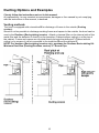
Ducting Options and Examples
Closely follow the instructions set out in this manual.
All responsibility, for any eventual inconveniences, damages or fires caused by not complying
with the instructions in this manual, is declined.
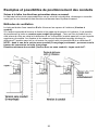
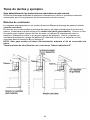
Venting methods
The hood is equipped with a transition B for discharge of fumes to the outside (Ducting
version).
Should it not be possible to discharge cooking fumes and vapour to the outside, the hood can be
used in the Ductless (Recirculating) version. Attach a charcoal filter on the internal side of the
metal filter and the deflector F directly on the transition (Cabinet without ceiling) or at the top of
the cabinet. Fumes and vapors are recycled directly through the deflector F (Cabinet without
ceiling) or by means of a duct connected to the transition B and the deflector F.
NOTE: For ductless (Recirculating) version only: purchase the Ductless Recirculating Kit.
Minimum Duct Size (Ducting/Ductless version): 6" Round Pipe.

11
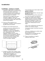
Preparation
This hood is designed to be installed inside a cabinet (only Blower unit housing) and fixed at the
bottom of the cabinet, check that the cabinet, its bottom, the hanging system of the cabinet and
the wall where cabinet is installed is strong enough to support the hood.
The inside of the cabinet should be accessible.
However, a qualified technician must verify suitability of the materials in accordance with the
type of cabinet.
We suggest to mount the cabinet onto the wall after having installed the hood.
Before making cutouts, make sure there is proper clearance.
NOTE: For ductless (recirculating) version only: Check that there is enough clearance
from ceiling and deflector once this last has been mounted to let an easy recirculation of air.
Hood installation height above cooktop is the users preference. The lower the hood is above the
cooktop, the more efficient the capturing of cooking odors, grease and smoke.
CAUTION: FOR GAS RANGES INSTALLATION: MOUNT THIS HOOD SO THAT THE
BOTTOM EDGE IS NOT LESS THAN 24" (61 CM) ABOVE THE COOKING SURFACE.
FOR ELECTRIC RANGES INSTALLATION: MOUNT THIS HOOD SO THAT THE BOTTOM
EDGE IS NOT LESS THAN 32" (81 cm) ABOVE THE COOKING SURFACE.
Check your ceiling height and the hood height maximum before you select your hood.

12
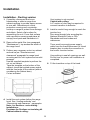
Installation
Installation - Ducting version
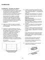
1. If possible, disconnect and move
freestanding or slide-in range from
cabinet opening to provide easier access
to rear wall. Otherwise put a thick,
protective covering over countertop,
cooktop or range to protect from damage
and debris. Select a flat surface for
assembling the unit. Cover that surface
with a protective covering and place all
canopy hood parts and hardware in it.
2. Remove the metal filter (see paragraph
"Maintenance") top access the inside of
the range hood.
3. Perform any necessary cutout on cabinet
and wall as per "Dimensions and
clearances" paragraph for range hood
mounting and for vent system and conduit
passage.
Use the supplied template to perform the
cut out on cabinet.
Tape the template on the bottom of the
cabinet, check that printed arrows match
with the front edge of the cabinet (without
considering the cabinet door).
Cut as indicated.
4. Install the vent system before the range
hood. See „Venting methods“ and
„Dimensions and clearance“ paragraphs.
Note - for Ductless - recirculating -
installations:
Purchase the Ductless recirculating kit
Cabinet without ceiling:
Vent system is not required.
Cabinet with ceiling:
A 6" section of duct may be required to
connect transition to deflector.
5. Install a conduit long enough to reach the
junction box.
Run wires through hole according the
National Electrical Code or CSA
Standards and local codes and
ordinances.
There must be enough power supply
cable from the fused disconnect (or circuit
breaker) box to make the connection in
the hood’s Junction box/es.
Use caulking to seal all openings on wall.
Do Not turn on power until installation is
completed.
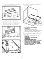
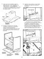
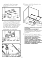
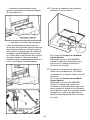
6. Fit the transition on top of the hood.

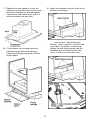
13
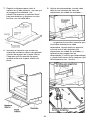
7. Regulate the rear spacer to cover the
clearance on the rear side once the hood
has been installed (see also paragraph
"Dimensions and clearances") and fix it
with two screws (one per side).
8. Fit the blower unit housing inside the
cabinet through the bottom opening.
Check that fixing springs goes over the
bottom panel..
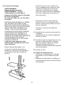
9. Apply two brackets (one per side) to the
blower unit housing.........
....... lock in place (check that each
bracket , once in position, is flush to the
front side of the blower unit housing)
tighten the side fixing screws (two per
brackets) and, from the inside of the
hood, fix with one screw each then .......

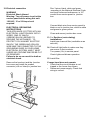
14
.......apply the two bigger brackets (lower
brackets) under the first two and....
..... tighten securely the two screws on
upper brackets, check that blower
housing is now well blocked, then, from
the inside of the hood, fix definitively the
lower brackets with one screw each.
10. Refinish the installation to cabinet with
two fixing screws.
For Ductless (recirculating)
installations
Cabinet without ceiling ONLY:
Install the deflector (available as an extra
kit) on the transition - snap into place.
11. Connect ducting to transition. Seal with
duct tape.
Do not use duct smaller than the
transition.
For Ductless - recirculating -
installations:
Cabinet with ceiling ONLY:
provide and install a section of duct long
enough to connect hood transition to
deflector once this has been installed
onto the cabinet ceiling (the deflector is
available as an extra kit).

15
12. Electrical connection
WARNING
Electrical Shock Hazard
Warning: Turn off power circuit at the
service panel before wiring this unit.
120 VAC, 15 or 20 Amp circuit
required.
ELECTRICAL GROUNDING
INSTRUCTIONS
THIS APPLIANCE IS FITTED WITH AN
ELECTRICAL JUNCTION BOX WITH 3
WIRES, ONE OF WHICH
(GREEN/YELLOW) SERVES TO
GROUND THE APPLIANCE. TO
PROTECT YOU AGAINST ELECTRIC
SHOCK, THE GREEN AND YELLOW
WIRE MUST BE CONNECTED TO THE
GROUNDING WIRE IN YOUR HOME
ELECTRICAL SYSTEM, AND IT MUST
UNDER NO CIRCUMSTANCES BE CUT
OR REMOVED.
Failure to do so can result in death or
electrical shock.
Remove the knockout and the Junction
box cover and install the conduit
connector (cULus listed) in junction box.
Run 3 wires; black, white and green
,according to the National Electrical Code
and local codes and ordinances, in 1/2"
conduit from service panel to junction
box.
Connect black wire from service panel to
black or red in junction box, white to white
and green to green-yellow.
Close and secure junction box cover.
13. For Ductless (recirculating)
installations
Install one charcoal filter (available as an
extra kit).
14. Check all light bulbs to make sure they
are secure in their sockets.
Turn power (On) in service panel.
Check lights and blower operation.
15. Install filter.
If range hood does not operate:
• Check that the circuit breaker is not
tripped or the house fuse blown.
• Disconnect power supply. Check that
wiring is correct.

16
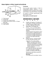
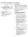
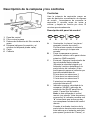
Description of the hood & Controls
1 Control panel
2 Grease filter
3 Grease filter release handle
4 Halogen lamp (position and nr. of lamps
may vary)
5 Sliding Glass
6 Hood canopy
Controls
Use the high suction speed in cases of
concentrated kitchen vapours. It is
recommended that the cooker hood suction
is switched on for 5 minutes prior to cooking
and to leave in operation during cooking and
for another 15 minutes approximately after
terminating cooking.
Description of control panel
AB CDE F
A - Lighting: dim lighting / full lighting /off
(loop control) - Works even with hood
in stand by and/or drawer closed.
B - Set Fan in Stand by (LED on the
lower side of the display ON).
C - ON/OFF Timer for selected speed
(visualizes the speed selected and
flashing LED on the lower side of the
display).
This knob permits the operation of the
cooker hood for a established period:
20 minutes if the speed selected is 1
15 minutes if the speed selected is 2
10 minutes if the speed selected is 3
5 minutes if the boost speed P is
selected.
D - Display showing: fan speed (1-2-3-
P), filter saturation indicator (F for
metal filter, C for charcoal filter)
Note: if in posses of the Remote
Control (see paragraph "List of
Part and Accessories") the display
shows a flashing "b" this to indicate
that the remote control battery
must be replaced.
When the led in the lower right side is
on, it indicates that the cooker hood
is ready for operation (“standby”
position), the flashing LED indicates
that the timer has been activated for
selected speed.
Warning!
The Charcoal filter saturation function

17
is not activated.
In order to activate the charcoal filter
saturation indicator, press buttons E
and F simultaneously for 3 seconds.
Initially, only letter F will be displayed,
then after the 3 seconds have passed,
letter C will be displayed as well,
indicating that the carbon filter
saturation control system is active.
To switch off the system, re-press the
same two buttons: letter C appear on
display and after 3 seconds it
disappears and the device will be
switched off.
E - Knob to decrease the speed: from
boost speed P to speed level 1.
F - Knob to increase (standby) speed to
boost speed P.
Attention! Boost speed P lasts 5
minutes after which the cooker hood
automatically sets the speed to level 2
(suction power).
Controlling the range hood with
sliding glass:
Closing the glass, all selected speed and
lights switched off.
Hood retains last speed (except P-boost-
speed) setting when glass is closed and re-
opened.
If the hood fails to operate correctly, briefly
disconnect it from the mains power supply for
almost 5 sec. by pulling out the plug. Then
plug it in again and try once more before
contacting the Technical Assistance Service.
Warning!
Always press the fan off button A before
disconnecting the hood from the mains
supply.
Reset filter saturation signal
Press knob B for about 3 seconds.
The letter F and/or C will disappear from the
display.

18
User Servicing and Maintenance Instructions
ATTENTION! Before performing any maintenance operation, isolate the hood from the electrical
supply by switching off at the connector and removing the connector fuse.
Or if the appliance has been connected through a plug and socket, then the plug must be
removed from the socket.
Cleaning
The cooker hood should be cleaned regularly
(at least with the same frequency with which
you carry out maintenance of the fat filters)
internally and externally. Clean using the
cloth dampened with neutral liquid detergent.
Do not use abrasive products. DO NOT USE
ALCOHOL!
WARNING: Failure to carry out the basic
cleaning recommendations of the cooker
hood and replacement of the filters may
cause fire risks.
Therefore, we recommend oserving these
instructions.
The manufacturer declines all responsibility
for any damage to the motor or any fire
damage linked to inappropriate maintenance
or failure to observe the above safety
recommendations.
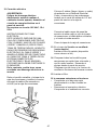
Grease Filter
Traps cooking grease particles.
The filters should be washed frequently
using non aggressive detergents, either by
hand or in the dishwasher, which must be set
to a low temperature and a short cycle.
When washed in a dishwasher, the grease
filter may discolour slightly, but this does not
affect its filtering capacity.
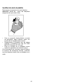
To remove the grease filter, pull the spring
release handle.
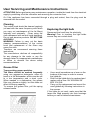
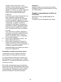
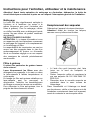
Replacing the light bulb
Disconnect the hood from the electricity.
Warning! Prior to touching the light bulbs
ensure they are cooled down.
• Use a small screwdriver as a lever on the
borders of the lamp in order to remove
the lightbulb.
• Slide out the lightbulb to be replaced and
replace with a new 12V 20W MAX 30°
Ø35 12V GU4.
• Carry out the replacement and mount the
new lightbulb by following instructions in
the reverse.
If the lights do not work, make sure that the
lamps are fitted properly into their housings
before you call for technical assistance.

19
French
Sommaire
Avis de sécurité important......................................................................................... 20
Exigences électriques et exigences d’installation .................................................. 22
Exigences électriques ................................................................................................................................22
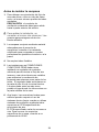
Avant d’installer la hotte .............................................................................................................................23
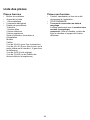
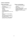
Liste des pièces .......................................................................................................... 24
Pièces fournies...........................................................................................................................................24
Pièces non fournies....................................................................................................................................24
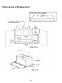
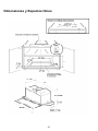
Dimensions et Dégagement....................................................................................... 25
Exemples et possibilités de positionnement des conduits.................................... 26
Méthodes de ventilation .............................................................................................................................26
Préparation.................................................................................................................................................27
Installation ................................................................................................................... 28
Installation - Version à conduit ...................................................................................................................28
Description de la hotte et des commandes.............................................................. 32
Commandes ...............................................................................................................................................32
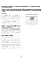
Instructions pour l’entretien, utilisateur et la maintenance.................................... 34
Nettoyage ...................................................................................................................................................34
Filtre à graisse............................................................................................................................................34
Remplacement des ampoules....................................................................................................................34
APPROUVÉ POUR LES APPAREILS DE TYPE RÉSIDENTIEL
POUR UNE UTILISATION RÉSIDENTIELLE SEULEMENT
LISEZ CES INSTRUCTIONS ET CONSERVEZ-LES
VEUILLEZ LIRE CES INSTRUCTIONS AU COMPLET AVANT DE COMMENCER.
L’INSTALLATION DE L’APPAREIL DOIT RESPECTER TOUS LES CODES EN
VIGUEUR.
IMPORTANT : Conservez ces instructions afin de pouvoir les remettre à
l’inspecteur-électricien de votre région.
INSTALLATEUR : Veuillez laisser ces instructions avec l’appareil pour le
propriétaire.
PROPRIÉTAIRE : Veuillez conserver ces instructions pour pouvoir vous y référer
plus tard.
Avertissement de sécurité : Coupez l’alimentation du circuit dans le panneau
électrique et verrouillez le panneau avant de raccorder les fils de cet appareil.
Exigence : 120 V c.a., 60 Hz circuit de dérivation de 15 V c.a., 20 Hz, de 15 ou 20
A.

20
LISEZ CES INSTRUCTIONS ET CONSERVEZ-LES
Avis de sécurité important
ATTENTION
UTILISER CET APPAREIL À DES FINS DE
VENTILATION GÉNÉRALE SEULEMENT.
NE PAS UTILISER CET APPAREIL POUR
ÉVACUER DES MATÉRIAUX OU DES
VAPEURS DANGEREUX OU EXPLOSIFS.
AVERTISSEMENT
POUR RÉDUIRE LES RISQUES
D’INCENDIE, DE CHOC ÉLECTRIQUE ET
DE BLESSURE, RESPECTER LES
DIRECTIVES SUIVANTES :
A. Utiliser cet appareil uniquement aux fins
prévues par le fabricant. Si vous avez des
questions à propos de l’appareil,
communiquez avec le fabricant.
B. Avant de faire l’entretien de l’appareil ou
de le nettoyer, coupez l’alimentation dans
le panneau électrique et verrouillez le
panneau en bloquant le dispositif
permettant d’empêcher d’activer
l’alimentation accidentellement. S’il n’est
pas possible de verrouiller l’accès au
panneau, fixez une étiquette très voyante
au panneau électrique.
C. Une personne qualifiée doit effectuer
l’installation et le câblage des fils
électriques en conformité avec tous les
codes et toutes les normes, y compris la
cote de résistance au feu.
D. Il est important de prévoir suffisamment
d’air pour assurer une bonne combustion
de l’équipement de chauffe et
l’évacuation adéquates des gaz par le
conduit de cheminé afin de prévenir les
refoulements d’air. Respectez les
directives et les normes de sécurité des
fabricants de l’équipement de chauffage,
comme celles publiées par la National
Fire Protection Association (NFPA), la
American Society for Heating,
Refrigeration and Air Conditioning
Engineers (ASHRAE) et le code des
autorités de votre région.
E. Au moment de couper ou de percer un
mur ou un plafond, assurez-vous de ne
pas endommager la filerie électrique ou
tout autre accès à un service publique.
F. Il faut toujours évacuer à l’extérieur les
systèmes à conduit.
ATTENTION
Pour réduire les risques d’incendie et
évacuer l’air correctement, assurez-vous
que le conduit mène à l’extérieur; il ne
faut pas évacuer l’air dans l’espace entre
les murs, dans les plafonds, dans les
greniers, les vides sanitaires ou les
garages.
AVERTISSEMENT
POUR RÉDUIRE DES RISQUES
D’INCENDIE, UTILISEZ UNIQUEMENT DES
CONDUITS EN MÉTAL.
Installez cette hotte en respectant toutes les
exigences mentionnées.
AVERTISSEMENT
Pour réduire les risques d’incendie et de
choc électrique, n’utilisez pas cette hotte
avec un contrôleur de vitesse à semi-
conducteurs.
AVERTISSEMENT
POUR RÉDUIRE LES RISQUES
D’INCENDIE DE GRAISSE SUR LES
CUISINIÈRES.
a) Ne laissez jamais la cuisinière sans
surveillance lorsqu’elle est réglée à une
haute température. Les débordements
par bouillonnement causent de la fumée
et des débordements de gras qui peuvent
s’enflammer. Faites chauffer l’huile
lentement, à une température basse ou
moyenne.
b) Faites toujours fonctionner la hotte
lorsque vous utilisez la cuisinière à une
haute température ou que vous faites
flamber des aliments (P. ex. : crêpes
Suzette, cerises jubilées, bœuf au poivre
flambé).
c) Nettoyez les hélices de ventilation
fréquemment. Il ne faut pas que la
La page est en cours de chargement...
La page est en cours de chargement...
La page est en cours de chargement...
La page est en cours de chargement...
La page est en cours de chargement...
La page est en cours de chargement...
La page est en cours de chargement...
La page est en cours de chargement...
La page est en cours de chargement...
La page est en cours de chargement...
La page est en cours de chargement...
La page est en cours de chargement...
La page est en cours de chargement...
La page est en cours de chargement...
La page est en cours de chargement...
La page est en cours de chargement...
La page est en cours de chargement...
La page est en cours de chargement...
La page est en cours de chargement...
La page est en cours de chargement...
La page est en cours de chargement...
La page est en cours de chargement...
La page est en cours de chargement...
La page est en cours de chargement...
La page est en cours de chargement...
La page est en cours de chargement...
La page est en cours de chargement...
La page est en cours de chargement...
La page est en cours de chargement...
La page est en cours de chargement...
La page est en cours de chargement...
La page est en cours de chargement...
-
 1
1
-
 2
2
-
 3
3
-
 4
4
-
 5
5
-
 6
6
-
 7
7
-
 8
8
-
 9
9
-
 10
10
-
 11
11
-
 12
12
-
 13
13
-
 14
14
-
 15
15
-
 16
16
-
 17
17
-
 18
18
-
 19
19
-
 20
20
-
 21
21
-
 22
22
-
 23
23
-
 24
24
-
 25
25
-
 26
26
-
 27
27
-
 28
28
-
 29
29
-
 30
30
-
 31
31
-
 32
32
-
 33
33
-
 34
34
-
 35
35
-
 36
36
-
 37
37
-
 38
38
-
 39
39
-
 40
40
-
 41
41
-
 42
42
-
 43
43
-
 44
44
-
 45
45
-
 46
46
-
 47
47
-
 48
48
-
 49
49
-
 50
50
-
 51
51
-
 52
52


ELICA EGL430S1 Guide d'installation
- Catégorie
- Hottes
- Taper
- Guide d'installation
- Ce manuel convient également à
dans d''autres langues
- English: ELICA EGL430S1 Installation guide
- español: ELICA EGL430S1 Guía de instalación