Legrand SD2-300 Incandescent Dual Slide Dimmer Guide d'installation
- Taper
- Guide d'installation

DESCRIPTION AND OPERATION
The SD2-300 Incandescent Dual Slide Dimmer is designed to replace a standard light switch or dimmer offering
dimming control of two separate circuits from one switch location. It controls incandescent loads only. To dim the
connected load move the slider down; to brighten the connected load move the slider up. Move the sliders to the
bottom to turn OFF the connected loads.
The Dual Slide Dimmer controls two separate lighting circuits independently. Each circuit can be separately set to
the ideal light level.
Caution: Use only with permanently installed 120VAC incandescent or halogen fixtures. To avoid overheating and
possible damage to other equipment, do not use to control receptacles, fluorescent lighting fixtures, motor-driven
appliances, or transformer-supplied appliances.
Important Notes
1. It is normal for the dimmer to feel warm to the touch during operation.
2. Protect the dimmer from dust and dirt when painting or spackling.
Derating
No derating is required for multigang installations.
INSTALLATION AND WIRING
WARNING
Disconnect power to the wall switch box by turning OFF
the circuit breaker or removing the fuse from the circuit before
installing the SD2-300, replacing lamps, or doing any electrical work.
1. Prepare the switch box
After the power is turned OFF at the circuit breaker box, remove the existing wall
plate and mounting screws. Pull the old switch out from the wall box.
2. Identify the type of circuit
You may connect the SD2-300 to a single pole circuit. If you are unable to clearly
identify some or all of the wires mentioned in this manual, you should consult
with a qualified electrician.
Caution – For your safety: Connecting a proper ground wire to the dimmer provides protection against electrical
shock in the event of certain fault conditions. If a proper ground is not available, consult with a qualified electrician
before continuing installation.
3. Prepare the Wires
Tag the wires currently connected to the existing switch so that they can be identified later. Disconnect the wires.
Make sure the insulation is stripped off of the wires to expose their copper cores to the
length indicated by the “Strip Gage” in Fig. 2. (approx. ½ inch).
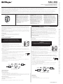
4. Wire the dimmer (Fig. 3)
Connect the wires from the circuits to the flying leads on the SD2-300 dimmer(s) as follows:
• Connectthegreenornon-insulated(copper)GROUNDwirefromthecircuittothegreen
wire on the dimmer.
• Connectthepowerwirefromthecircuit(HOT)totheblackwireonthedimmer.
• Connectoneloadtotheyellowwireonthedimmer.
• Connecttheotherloadtothebrownwireonthedimmer.
5. Put the dimmer into the wallbox. Use the captive screws on the mounting strap to secure the dimmer to the
wallbox.
6. Restorepowertothecircuit.Turnonthebreakerorreplacethefuse.
7. Attach the cover plate.
MADE IN CHINA
PATENTS
PENDING
WARRANTY VOID IF CASE OPENED
TURN OFF POWER
GREEN
BLACK YELLOW
(HOT)
120V/60Hz
BROWN
Load 1
Load 2
NEUTRAL
NEUTRAL
Fig. 3: Single Pole Wiring
TROUBLESHOOTING
Lights are flickering
• Lamphasabadconnection.
• Checkwireconnectionstomakesuretheyaresecuredrmly.
• Theremaybeacircuitwiringissue.Youshouldalwaysuseaseparateneutralwireforthecircuitconnectedto
the dimmer. If two 120VAC hots from the breaker box share the same neutral and one of them has a very large
load, it could cause a voltage drop on the other hot. This can cause flickering.
Light does not turn ON
• Checktoseeifthecircuitbreakerorfusehastripped.
• Checktoseeifthelampisburnedout.
Cover Plates
WattStopper SD dimmers fit behind industry standard decorator style switch cover plates.
Strip Gage
1/2"
12.7 mm
Fig. 2 : #12 or
#14 AWG
Ground
HOT (power from
circuit box)
LOAD
(power
to lamp)
NEUTRAL
Fig 1: Typical Single Pole
Switch Wiring
SD2-300
v2
Incandescent Dual Slide Dimmer
Gradateur d’éclairage à glissière double à incandescence
Regulador deslizante doble incandescente
PERMANENT
INCANDESCENT
FIXTURES
300W EACH
SD2-300
TOP
120 VAC
60HZ
Installation Instructions · Notice d'Installation · Instrucciones de Instalación
SPECIFICATIONS • CARACTÉRISTIQUES • ESPECIFICACIONES
READ AND SAVE THESE INSTRUCTIONS
To be installed by a certified electrician or other qualified
person.
WARNING – To prevent severe shock or electrocution,
always turn power off at the service panel before installing
this unit, working on the circuit, or changing a lamp.
CAUTION – To reduce the risk of overheating and possible
damage to other equipment, do not install incandescent
dimmer to control a receptacle, a fluorescent light or bulb,
a motor-operated appliance, or a transformer-supplied
appliance.
• Donotusedimmerwithincandescentlampswhosepower
requirements exceeds maximum power (stated in Watts) of
the dimmer.
• Donotconnectdimmertopowersourceotherthan
120VAC, 60 Hz only.
• A25Wminimumloadisrequired.
• Usecopperwireonly.
LISEZ ET CONSERVEZ CES INSTRUCTIONS
Ce dispositif doit être installé par un électricien certifié ou
une autre personne qualifiée.
AVERTISSEMENT – Pour éviter des décharges électriques
importantes ou l’électrocution, coupez toujours le courant
au niveau du panneau d’alimentation avant de monter cette
unité, de travailler sur le circuit ou de changer une lampe.
ATTENTION – Pour réduire le risque de surchauffe et de
dommages possibles sur d’autres équipements, n’installez
pas ce dispositif pour contrôler une prise, une ampoule ou
lampe fluorescente, un appareil motorisé ou un appareil
alimenté par un transformateur.
• N’utilisezpascegradateuravecdeslampesà
incandescenced’unepuissancesupérieureàlapuissance
maximum (exprimée en Watts) du gradateur.
• Neraccordezpascegradateuràunesource
d’alimentation autre qu’une source d’alimentation de
120 V c.a., 60 Hz.
• Unechargede40Wminimumestrequise.
• N’utilisezquedesfilsencuivre.
LEA Y GUARDE ESTAS INSTRUCCIONES
La instalación debe estar a cargo de un electricista
certificado u otra persona calificada.
ADVERTENCIA. Para evitar una fuerte descarga eléctrica
o la electrocución, siempre desconecte el suministro
eléctrico en el panel de servicio antes de instalar esta
unidad, trabajar en el circuito o cambiar una lámpara.
PRECAUCIÓN. Para reducir el riesgo de sobrecalentamiento
y posibles daños a otros equipos, no instale el atenuador
incandescente para controlar un receptáculo, una luz o una
bombilla fluorescentes, un aparato accionado por motor
o un aparato con transformador.
• Noutiliceelatenuadorconlámparasincandescentes
cuyos requisitos de potencia superen la potencia máxima
(expresada en vatios) del atenuador.
• Noconecteelatenuadoraunafuentedealimentación
que sea distinta de 120 V CA y 60 Hz solamente.
• Serequiereunacargamínimade40W.
• Usesolamentecablesdecobre.
INSTRUCTIONS EN FRANÇAIS
SANTACLARA,CA95050
© 2013 WattStopper
Voltage: 120 VAC, 60 Hz, Maximum Load Rating: 300 W per load circuit, Minimum Load Rating: 25 W per load circuit, Load (Single Pole): Incandescent, Environment: Indoor use only, Operating Temperature: 0-25°C (32-77°F),
Humidity:93% RH, non-condensing, Electrical Supply Wire Requirement, Minimum temperature rating: 75°C (167°F), Tools Needed: Insulated Screwdriver, Wire Strippers
Tension : 120 V c.a., 60 Hz, Capacité de charge maximum : 300 W par circuit de charge, Capacité de charge minimum : 25 W par circuit de charge, Charge (unipolaire) :.À incandescence, Environnement : Utilisation intérieure
uniquement, Température de fonctionnement : 0-25 °C (32-77 °F),
Humidité:93 % d’humidité relative, sans condensation, Exigences concernant les fils d’alimentation électrique, Limite de température minimum : 75 °C (167 °F), Outils nécessaires : Tournevis isolé, dénudeurs de fil
Voltaje: 120 VAC, 60 Hz, Carga nominal máxima: 300 W por circuito de carga, Carga nominal mínima: 25 W por circuito de carga, Carga (polo único): Incandescente, Entorno: Solo para uso en interiores; Temperatura de
funcionamiento: 0-25°C (32-77°F),
Humedad:93% de humedad relativa, sin condensación, Requisito de cables del suministro eléctrico, Temperatura nominal mínima: 75°C (167°F), Herramientas necesarias: Destornillador aislado, pelacables
DESCRIPTION ET FONCTIONNEMENT
LegradateuràglissièredoubleSD2-300pourchargesàincandescenceestconçupourremplacer
ungradateurouinterrupteurd'éclairagestandardetoffrirunecommandedegradationdedeux
circuitsséparésàpartird'unseulemplacementdeinterrupteur.Ilcontrôleuniquementdescharges
àincandescence.Pourbaisserl'intensitédelachargereliée,déplacezlacoulisseverslebas;pour
l'augmenter,déplacezlacoulisseverslehaut.Déplacezlesglissièresjusqu'enbaspourCOUPERles
chargesreliées.
Legradateuràglissièredoublecommandeindépendammentdeuxcircuitsd'éclairageséparés.Chaque
circuitpeutêtrerégléséparémentàunniveaud'éclairageidéal.
Attention : N'utilisezcedispositifqu'avecdesluminaireshalogènesouàincandescencede120V
installésdefaçonpermanente.Pouréviterlasurchauffeetdesdommagespossiblessurd'autres
équipements,n'utilisezpascedispositifpourcontrôlerdesprises,desluminairesuorescents,des
appareilsmotorisésoudesappareilsalimentéspartransformateur.
Remarques importantes
1. Il est normal que le gradateur soit chaud pendant son fonctionnement.
2. Protégezlegradateurdelapoussièreetdelasaletépendantdestravauxdepeintureetde
rebouchage.
Déclassement
Aucundéclassementn'estnécessairepourlesinstallationsmultiples.
INSTALLATION ET CÂBLAGE
ATTENTION
Mettez le boîtier l’interrupteur mural hors tension en COUPANT le disjoncteur
de circuit ou en retirant le fusible du circuit avant d'installer le SD2-300,
de remplacer des lampes ou d'effectuer tous travaux d'électricité.
1. Préparezleboîtierl’interrupteur
Une fois que le courant est COUPÉ au niveau du disjoncteur de circuit,
retirezlaplaquemuraleetlesvisdemontageexistantes.Enlevez
l'ancieninterrupteurduboîtiermural.
2. Identiezletypedecircuit
VouspouvezraccorderleSD2-300àuncircuitunipolaire.Sivous
n'arrivezpasàidentierclairementquelques-unsoutouslesls
mentionnésdanscemanuel,veuillezconsulterunélectricienqualié.
Attention –Pourvotresécurité:leraccordementd'unldeterre
appropriéaugradateurassureuneprotectioncontrelesdécharges
électriquesdanslecasdecertainesdéfaillances.Siunemiseàlaterreappropriéen'estpasdisponible,
contactezunélectricienqualiéavantdepoursuivrel'installation.
3.Préparezlesls
Étiquetezleslsactuellementraccordésàl’interrupteurexistantandepouvoirlesidentierpar
lasuite.Débranchezlesls.Assurez-vousquel'isolantestenlevédeslspourmettreànuleurs
conducteursencuivresurlalongueurindiquéeparle«Gabaritdedénudage»delaFig.2(env.0,5po).
4. Câblezlegradateur(Fig.3)
RaccordezleslsdescircuitsauxcâblesvolantsduoudesgradateursSD2-300
comme suit :
• RaccordezleldeTERRE(cuivre)nonisoléouvertducircuitaulvertdu
gradateur.
• Raccordezleld'alimentationducircuit(SOUSTENSION)aulnoirdugradateur.
• Raccordezunechargeauljaunedugradateur.
• Raccordezl'autrechargeaulmarrondugradateur.
5. Placezlegradateurdansleboîtiermural.Utilisezlesvisimperdablessurlacourroiedemontage
pourxerlegradateuràsonboîtiermural.
6. Remettezlecircuitsoustension.Enclenchezledisjoncteurdecircuitouremettezlefusible.
7. Fixezlescaches.
FABRIQUÉ EN CHINE
BREVETS EN INSTANCE
ANNULATION DE LA GARANTIE
EN CAS D'OUVERTURE DU BOÎTIER
COUPER L'ALIMENTATION
VERT
NOIR JAUNE
(SOUS TENSION)
120 V/60 Hz
MARRON
Charge 1
Charge 2
NEUTRE
NEUTRE
Fig. 3 : Câblage d'un circuit unipolaire
DÉPANNAGE
L'éclairage vacille
• Lalampeestmalraccordée.
• Vériezlesraccordementsdeslspourvérierqu'ilssontbienxés.
Gabarit de
dénudage
1/2"
12,7 mm
Fig. 2 : AWG n° 12
ou n° 14
Terre
SOUS TENSION (alimentation
provenant du disjoncteur de circuit)
CHARGE
(alimentation
apportée à la
lampe)
NEUTRE
Fig. 1 : Câblage typique d'un
interrupteur unipolaire
La page est en cours de chargement...
-
 1
1
-
 2
2


Legrand SD2-300 Incandescent Dual Slide Dimmer Guide d'installation
- Taper
- Guide d'installation
dans d''autres langues
Documents connexes
-
wattstopper SD-1003 Incandescent Multi-way Slide Dimmer Guide d'installation
-
Legrand SDMLV-603 Magnetic Low Voltage Multi-way Slide Dimmer Guide d'installation
-
-
-
-
-
-
Legrand HDMLV-703, HDMLV-1103 Magnetic Low Voltage Multi-way Paddle Dimmer (Tri-Lingual) Guide d'installation
-
-