Magnetrol Thermatel TG1/TG2 Mode d'emploi
- Taper
- Mode d'emploi

Thermal
Dispersion
Level/Flow/Interface
Switch
Installation and Operating Manual
THERMATEL
®
MODEL TG1/TG2
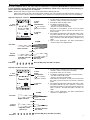
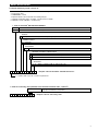
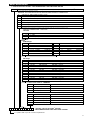
Model TG1/TG2
with twin tip sensor
Model TG1/TG2
with spherical tip sensor
Model TG1/TG2
with low flow body sensor
DIN rail
Model TG1

These units are in compliance with:
1.The EMC directive 2014/30/EU.
2.Directive 2014/34/EU for equipment or protective system intended for
use in potentially explosive atmospheres. EC-type examination certifi-
cate number ISSeP00ATEX006 (DIN Rail housing) and
ISSeP00ATEX007X (sensor and sensor enclosure).
2
UNPACKING
Unpack the instrument carefully. Make sure all components
have been removed from the foam protection. Inspect all
components for damage. Report any concealed damage to
the carrier within 24 hours. Check the contents of the car-
ton/crates against the packing slip and report any discrep-
a
ncies to Magnetrol. Check the nameplate model number
to be sure it agrees with the packing slip and purchase
order. Check and record the serial number for future refer-
ence when ordering parts.
MOUNTING
SPECIAL CONDITIONS FOR ATEX INTRINSICALLY SAFE USE
Pre-amplifier
nameplate:
-
partnumber
- serial n°
- tag n°
Amplifier
n
ameplate:
- partnumber
- serial n°
-
tag n°
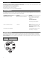
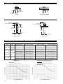
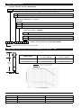
FLOW LEVEL
- During the installation, the user and the installer shall ensure the internal temperatures of the enclosure containing the
amplifier don’t exceed + 70 °C (160 °F) under the worst unfavourable conditions.
The worst unfavourable conditions are present with an external ambient temperature of + 70 °C (160 °F) and a maxi-
mum heating transmission by the installation.
If one of these temperature exceeds + 70 °C (160 °F), either the high temperature version, or the standard one with
enclosure extension shall be used.
- When the material is equipped with an aluminium enclosure, all precautions shall be taken in order to avoid all impacts
or frictions which can cause ignition of the potentially explosive atmosphere.
Flow / No flow
Low Flow
Body
Overflow
Overflow
tank
Overflow
tank
Off gas
Gas vent
Switch at set flow rate
Output line
Additive flow
output line
Input line
Interface
High level
alarm
Low level alarm
Pump protection
Leak detection
For flow switches calibrated by MAGNETROL, install the probe near the centerline of the pipe. If not calibrated by MAG-
NETROL, install the probe at least 1⁄4 diameter depth into the pipe. For best results it is recommended to install the switch
with five diameters of straight run upstream and downstream of the sensor.

3
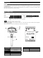
MOUNTING
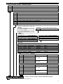
WIRING
®
POWER
+
-
SENSOR
1 2 3 4
connect ground in case of
excessive noise interference
Standard 2-wire shielded instrument cable
max 500 m (1640 ft)
Green grounding screw
Direction of
flow
Direction of
fl
ow
Direction of
level movement
Threaded Welded flange
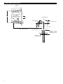
Alarm relay
Potentiometer
Power LED
Error LED
Relay mA Power
®
ALARMDELAY
LOW HIGH
FAIL-SAFE
+–
+–
mA
24 VDC
POWER
ERROR
+–
SENSOR
Time Delay
Potentiometer
Fail-safe

4
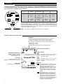
Pre-amplifier settings
Amplifier settings and LED indications
CALIBRATION
®
S1
S
2
1 2
1 2
RTD CURRENT
S
ENSITIVITY
+
-
OPEN
OPEN
T
he units are factory set to the “Default” dip switch positions, except for units with TMH
sensors as these are set to “For TMH sensors”. These settings should be valid for
most liquid level, interface and flow cases. For gaseous low flow applications or for
specific liquid applications it may happen that the set point cannot be established.
Change the settings in these cases from “Default” to “Low flow gas” depending what
is needed to establish the setpoint.
NOTE: The settings on TMH sensors should never be changed.
Alarm relay Potentiometer
Power LED:
Unit powered = green LED ON
Error LED:
OFF: unit operates normal
BLINKS: unit has registered an error
®
ALARMDELAY
LOW HIGH
FAIL-SAFE
+–
+–
mA
24 VDC
POWER
ERROR
+–
SENSOR
Time Delay Potentiometer:
Before calibration, turn fully
counterclockwise until click
(max. 20 turns) = 0 s
mA signal:
The mA is a non linear signal of the actual process conditions;
- for flow: mA output increases as the flow rate increases
- for level: mA output increases when in a wet condition.
Error reporting is determined by setting of the Fail Safe mode;
- failsafe low ≤ 3,6 mA
- failsafe high ≥ 22 mA
The mA value depends upon sensor and application.
Fail-safe:
=Low level Fail-safe – the relay is ener-
gized when the flow is greater than the
alarm point or when the sensor is
immersed. The relay becomes de-ener-
gized when the flow is equal to or less
than the alarm set point or when the
sensor is dry (or in the low conductivity
media)
=High level Fail safe – the relay is ener-
gized when the flow is less than the
alarm point or when the level is lower
than the less than the switch point. The
relay will de-energize when the flow
reaches or exceeds the alarm point or if
the sensor becomes immersed (or in
the high conductivity media).
LED indication:
TG1
green LED ON = safe
(one or more of the 4 green LED's)
yellow LED ON = reaching switch point
Red LED ON = alarm
TG2
green LED ON = safe
(one or more of the 4 green LED's)
yellow LED ON = reaching switch point
None = alarm
Open dipswitch
Closed dipswitch
D
IP switch
positions
Default Low flow gas
Temperatures
≥
+100 °C (+212 °F)
F
or TMH
sensors
RTD current (S1)
1 Closed Open Open Closed
2 Open Closed Closed Open
Sensitivity (S2)
1 Open Open Open Closed
2 Closed Closed Closed Open
For factory calibrated devices, the switch setup and calibration is completed by MAGNETROL for optimal performance
i
n your application. The dip-switch settings and/or potentiometers should only be adjusted for troubleshooting pur-
poses if the factory calibration was not sufficient.

5
High flow / High level - Interface
CALIBRATION
NOTE: Ensure that settings on page 4 have been verified before calibrating this unit.
Adjust level, interface or flow to the desired alarm condition. Units are preferably field calibrated under operating con-
ditions or bench calibrated if the real conditions can be simulated. Consult factory when this cannot be established.
1. Set Time delay to minimum (turn max 20 turns counter-
clockwise or until a clicking sound is heard).
2. Set Failsafe switch in “High” mode.
3. Set Alarm potentiometer until:
- red LED is ON for TG1 model
- all LED’s are OUT for TG2 model.
Relay will be de-energized, as flow or level is higher
than the actual set point or the unit sees the most con-
ductive media.
4. Reset Alarm potentiometer until Red LED (TG1) is OFF
and yellow LED lids UP (turn clockwise) – tweek the
potentiometer slowly back and forth until the desired set
point is reached = Red LED ON (TG1) / All LED’s OUT
(TG2).
5. Only for level applications: turn alarm potentiometer
counterclockwise one additional turn.
1. Set Time delay to minimum (turn max 20 turns counter-
clockwise or until a clicking sound is heard).
2. Set Failsafe switch in “Low” mode
3. Set Alarm potentiometer until: (turn counterclockwise)
- red LED is ON for TG1 model
- all LED’s are OUT for TG2 model.
Relay will be de-energized, as flow or level is lower than
the actual set point or the unit sees the least conductive
media.
4. Reset Alarm potentiometer until Red LED (TG1) is OFF
and yellow LED lids UP (turn clockwise) – tweek the
potentiometer slowly back and forth until the desired set
point is reached = Red LED ON (TG1) / all LED’s out
(TG2)
5. Only for level applications: turn alarm potentiometer
clockwise 1/2 additional turn.
Low flow / No flow / Low level - Interface
3 and 4.
Alarm
potentiometer
1
. Time
Delay = 0
ALARM
1. Time
Delay = 0
2. Fail safe
= high
®
A
LARMDELAY
LOW HIGH
FAIL-SAFE
+
–
+
–
mA
24 VDC
POWER
ERROR
+–
SENSOR
2. Fail safe
= low
less sensitive
more sensitive
3 and 4.
Alarm
potentiometer
®
A
LARMDELAY
LOW HIGH
FAIL-SAFE
+–
+–
mA
2
4 VDC
POWER
ERROR
+–
SENSOR
less sensitive
more sensitive
Higher mA value
mA value:
Process
condition:
LED
indication:
High flow / Flow
Wet sensor
Low flow / No Flow
Dry sensor
Lower mA value
Setpoint
GGGGYR
ALARM
Lower mA value
mA value:
Process
condition:
LED
indication:
High flow / Flow
Wet sensor
Low flow / No Flow
Dry sensor
Higher mA value
Setpoint
GGGGYR
Red LED ON (TG1) / All LED’s out (TG2).
Red LED ON (TG1) / All LED’s out (TG2).
For factory calibrated devices, the switch setup and calibration is completed by MAGNETROL for optimal performance
in your application. The dip-switch settings and/or potentiometers should only be adjusted for troubleshooting pur-
poses if the factory calibration was not sufficient.

6
Symptom (
at DIN Rail electronics)
Problem Solution
Yellow LED does not go ON Switch point cannot be established Adjust sensitivity in sensor housing
(check S1 and S2 switch settings –
see page 4)
Check FAIL-SAFE position
Check sensor connection
Green power LED OFF No power Check power supply
Check wiring at power terminals
Red Error LED blinks and
value is ≤ 3,6 mA or ≥ 22 mA
A malfunction on the unit
is detected
Check wiring to sensor
Check wiring between electronics and
sensor
Voltage at sensor terminals on DIN
Rail housing should read +/- 14 Volts
Consult factory
Red Error LED blinks at high level/flow
and turns OFF at low level/flow
Unit is set too sensitive Change setting to "Lower" Sensitivity
in sensor housing (check S1 and S2
switch settings – see page 4)
FAULT INDICATION
T
ROUBLESHOOTING
T
G1/TG2 have continuous diagnostics to ensure that the signal from the sensor is within a select range. If the electronics detect
an “out of range” signal, the switch has registered an instrument error.
3,6 mA signal when unit is set for low level fail-safe.
22 mA signal when unit is set for high level fail-safe.
E
rror LED blinks and the relay de-energizes.
If a fault is detected, refer to section “TROUBLESHOOTING”.
The TG1/TG2 switches have various settings to handle a wide variety of flow and level applications. If the switch is not per-
forming properly, check the switch settings on page 4 or the following:
RESISTANCE VALUES
The following table provides the expected resistance values for the sensor. These should be within the specified limits.
Before testing the resistance values of the wires, switch power off and disconnect sensor wires. When re-connecting the
sensor, assure that the pairs (one is labelled 1) remain together as a pair. Reversing pairs of wire has no impact on the per-
formance of the unit.
®
POWER
+
-
SENSOR
1 2 3 4
Terminal pairs Resistance
1 and 2 (labelled 1) 90 to 180 Ω (275 Ω for TMH)
3 and 4 90 to 180 Ω (275 Ω for TMH)

7
M
AINTENANCE
T
he probe may be cleaned by soaking, spraying solvents or detergent and water onto the sensor tubes, or by ultrasonic clean-
ing. Lime deposits may be safely removed by soaking in 20 % hydrochloric acid. Warming to +65 °C (+150 °F) is permissible
to speed this process.
For unusual cleaning problems, contact the factory and determine the exact materials of construction and chemical compat-
ibility before using strong acids or unusual cleansers.
C
leaning
REPLACEMENT PARTS
1X
74
2 3 8 9 105 6
Digit in partn°:
T G
Partn°:
Serial n°:
X = product with a specific customer requirement
See nameplate, always provide complete partn° and
serial n° when ordering spares.
(5) DIN rail housing & electronics
Digit 3 Replacement part
1 089-7905-001
2
089-7905-002
(2) Housing cover
Digit 8 Replacement part
2 or T 004-9105-001
6 004-9142-001
Replacement part
(1) PC board 030-9114-001
(3) "O"-ring 012-2101-345
(4) Sensor consult factory
4
3
2
5
1
®
ALARMDELAY
LOW HIGH
FAIL-SAFE
+–
+–
mA
24 VDC
POWER
ERROR
+–
SENSOR
NOTE: The switch will require recalibration (see page 5) following probe or electronics replacement.
E X P E D I T E S H I P P L A N ( E S P )
Several parts are available for quick shipment, within max. 1 week after factory receipt of purchase order, through the
Expedite Ship Plan (ESP).
Parts covered by ESP service are conveniently grey coded in the selection tables.

8
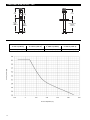
DIMENSIONS IN MM (INCHES)
D
IN rail
Sensor housing
Separate or seal
welded flange
ø 118 (4.63)
Rotation clearance
76 (3.00)
70
(2.75)
Single cable entry
®
A
L
A
R
M
D
E
L
A
Y
L
O
W
H
I
G
H
F
AI
L
-
SAFE
P
O
W
E
R
E
R
R
O
R
max. 500 m (1640 ft)
cable is ordered separately
5
5
(
2
.1
6
)
75 (2.95)
1
1
0
(
4
.3
3
)
35 (1.38)
114
(4.49)
Overhead clearance 70 (2.75)
Threaded: 46 (1.81)
Welded flange: 60 (2.36)
Heat extension: 223 (8.78)

9
MODEL IDENTIFICATION
1. Code for Thermatel
®
DIN RAIL ELECTRONICS
POWER SUPPLY
MOUNTING
0D Remote DIN rail mounted electronics
APPROVAL
A0 ATEX II 1 G EEx ia IIB T5, intrinsically safe
2 24 V DC
OUTPUT
1 2 Amp SPDT alarm relay with mA output signal (non linear / non scaleable)
A
complete measuring system consists of:
1
. THERMATEL
®
D
IN RAIL electronics and sensor housing
2. Connecting cable
3. THERMATEL
®
sensor
4
. Optional: Order code for thread-on mounting flanges
5. Optional: Retractable probe assembly, consult factory for details
6. Optional: Factory calibration, consult factory
SENSOR HOUSING / CABLE ENTRY
2. Code for connecting cable (standard 2-wire shielded instrument cable – 0,50 mm
2
)
1 22 233 7
complete code for connecting cable
001- 500
From 1 m (3.28 ft) min. to 500 m (1640 ft) max.
Specify in increments of 1 m (3.28 ft)
T
D
2 0
1
G A 0
complete code for Thermatel
®
TG1/TG2 electronics
TG1 Electronics with standard LED flow indication
TG2 Electronics with LED flow indication per NAMUR NE 44
T IP 65, Cast aluminium, M20 x 1,5 cable entry
2 IP 65, Cast aluminium, 3/4" NPT cable entry
6 IP 65, Cast stainless steel, 3/4" NPT cable entry
X = product with a specific customer requirement

10
CONNECTIONS
DIMENSIONS IN MM (INCHES) – TMA/TMB/TMC/TMD
PRESSURE/TEMPERATURE RATING – TMA/TMB/TMC/TMD
Threaded Welded flange ASME - EN
Insertion
length
BSP connection
Insertion
length
Insertion
length
NPT connection
Threaded Sensor
F
langed Sensor
I
nsertion length
NPT connection
Insertion length
B
SP connection
I
nsertion
l
ength
ø 22,9 (0.90)
ø
22,9 (0.90)
Standard: 46 (1.81)
With heat extension: 223 (8.78)
Standard: 60 (2.36)
With heat extension: 223 (8.78)
TMA/TMB sensors
TMC/TMD sensors with material code A or D
Insertion length = minimum length
Insertion length > minimum length
Process temperature (°C)
Process pressure (bar)
Sensor
Material
code
Insertion length
Maximum process pressure
@ +40 °C (+100 °F) @ +120 °C (+250 °F) @ +200 °C (+400 °F)
TMA, TMB
A All 41,4 bar (600 psi) 33,8 bar (490 psi) 28,6 bar (415 psi)
K, M, N All 27,6 bar (400 psi) 22,4 bar (325 psi) 19,0 bar (275 psi)
TMC, TMD
A, D, K,
M, N
= minimum length 207 bar (3000 psi) 170 bar (2460 psi) 148 bar (2140 psi)
> minimum length 128 bar (1850 psi) 105 bar (1517 psi) 91,0 bar (1320 psi)
TMC, TMD B, F
= minimum length 207 bar (3000 psi) 181 bar (2627 psi) 161 bar (2340 psi)
> minimum length 103 bar (1500 psi) 90,6 bar (1313 psi) 80,7 bar (1170 psi)
TMC, TMD C, G
= minimum length 172 bar (2500 psi) 147 bar (2125 psi) 137 bar (1980 psi)
> minimum length 82,8 bar (1200 psi) 70,3 bar (1020 psi) 65,5 bar (950 psi)
Process temperature (°C)
Process pressure (bar)
Ma
t
er
i
al
c
ode A
Materi
al
c
ode
K, M
or N

11
MODEL IDENTIFICATION
3. Code for Thermatel
®
TG1/TG2 – STANDARD SENSOR
complete code for Thermatel
®
TG1/TG2 STANDARD SENSOR
T 0M
M
ATERIAL OF CONSTRUCTION FOR SENSOR AND PROCESS CONNECTION
TMA Spherical tip - standard max +120 °C (+250 °F)
TMB Spherical tip - with heat extension max +200 °C (+400 °F)
T
MC Twin tip - standard max +120 °C (+250 °F)
TMD Twin tip - with heat extension max +200 °C (+400 °F)
X = product with a specific customer requirement
INSERTION LENGTH – MINIMUM
INSERTION LENGTH – SELECTABLE – Specify per cm (0.39") increment
Sensor Process connection
0 0 5 5 cm (2")
TMA, TMB
NPT
0 0 6 5,5 cm (2.17") flanged
0 0 7 7 cm (2.76") BSP
0 0 6 5,5 cm (2.17")
TMC, TMD
NPT, flanged
0 0 8 7,5 cm (3") BSP
Sensor Process connection
0 0 6 Minimum 6 cm (2.36")
TMA, TMB
NPT
0 0 7 Minimum 7 cm (2.76") flanged
0 0 8 Minimum 8 cm (3.15") BSP
0 0 7 Minimum 7 cm (2.76")
TMC, TMD
NPT, flanged
0 0 9 Minimum 9 cm (3.54") BSP
3 3 0 Maximum 330 cm (130") all all
P
RO
CE
S
S
CO
NNE
CT
IO
N
–
S
IZ
E
/T
Y
P
E
T
h
r
e
a
d
e
d
1 1
0
3
/4
"
N
P
T
2 1
0
1
"
N
P
T
2 2
0
1
"
B
S
P
(
G
1
")
ASME flanges
¿
Not suitable for zone 0 applications in combination with hermetically sealed relay; use in this case material code D.
A
316/316L (1.4401/1.4404) stainless steel
➀
B Hastelloy
®
C (2.4819) – TMC/TMD only
C Monel
®
(2.4360) – TMC/TMD only
D 316/316L (1.4401/1.4404) stainless steel – TMC/TMD only
F Hastelloy
®
C (2.4819), NACE
G Monel
®
(2.4360), NACE
K 316/316L (1.4401/1.4404) stainless steel, ASME B31.3
M 316/316L (1.4401/1.4404) stainless steel, ASME B31.3 and NACE
N 316/316L (1.4401/1.4404) stainless steel, NACE
350 1 1/2" 600 lbs ASME RF
430 2" 150 lbs ASME RF
440 2" 300 lbs ASME RF
450 2" 600 lbs ASME RF
2 3 0 1" 150 lbs ASME RF
240 1" 300 lbs ASME RF
250 1" 600 lbs ASME RF
330 1 1/2" 150 lbs ASME RF
340 1 1/2" 300 lbs ASME RF
No threads
–
only for use with compression fitting
000 Compression fitting (customer-supplied)
BB0 DN 25 PN 16/25/40 EN 1092-1 Type A
BC0 DN 25 PN 63/100 EN 1092-1 Type B2
CB0 DN 40 PN 16/25/40 EN 1092-1 Type A
CC0 DN 40 PN 63/100 EN 1092-1 Type B2
DA0 DN 50 PN 16 EN 1092-1 Type A
DB0 DN 50 PN 25/40 EN 1092-1 Type A
DD0 DN 50 PN 63 EN 1092-1 Type B2
DE0 DN 50 PN 100 EN 1092-1 Type B2
EN flanges

12
DIMENSIONS IN MM (INCHES) – TMH
PRESSURE/TEMPERATURE RATING – TMH
Maximum process pressure
@ +40 °C (+100 °F) @ +120 °C (+250 °F) @ +200 °C (+400 °F) @ +450 °C (+850 °F)
414 bar (6000 psi) 339 bar (4920 psi) 295 bar (4280 psi) 233 bar (3380 psi)
Process temperature (°C)
Process pressure (bar)
251
(9.88)
Insertion
length
BSP
connection
Insertion
length
NPT
connection
Insertion length
Flanged
connection
273
(10.75)
254
(10.00)
Ø 21,9
(0.86)
Ø
21,9
(
0.86)

13
MODEL IDENTIFICATION
3. Code for Thermatel
®
TG1/TG2 – HIGH TEMPERATURE / HIGH PRESSURE SENSOR
complete code for Thermatel
®
TG1/TG2
HIGH TEMPERATURE /HIGH PRESSURE SENSOR
T
0
M H
TMH High temperature / high pressure twin tip – max +450 °C (+850 °F) / max 414 bar (6000 psi)
¿
¿
N
ot available with retractable probe assembly.
X = product with a specific customer requirement
INSERTION LENGTH – MINIMUM
Process connection
0 0 6 5,5 cm (2.17") NPT
0 0 7 7 cm (2.76") flanged
0 0 8 7,5 cm (3") BSP
Process connection
0 0 7 Minimum 7 cm (2.76") NPT
0 0 8 Minimum 8 cm (3.15") flanged
0 0 9 Minimum 9 cm (3.54") BSP
0 9 1 Maximum 91 cm (36") all
INSERTION LENGTH – SELECTABLE – Specify per cm (0.39") increment
PROCESS CONNECTION – SIZE/TYPE
Threaded
110 3/4" NPT
210 1" NPT
220 1" BSP (G 1")
EN flanges
BB0 DN 25 PN 16/25/40 EN 1092-1 Type A
BC0 DN 25 PN 63/100 EN 1092-1 Type B2
BG0 DN 25 PN 250 EN 1092-1 Type B2
CB0 DN 40 PN 16/25/40 EN 1092-1 Type A
CC0 DN 40 PN 63/100 EN 1092-1 Type B2
CG0 DN 40 PN 250 EN 1092-1 Type B2
CJ0 DN 40 PN 400 EN 1092-1 Type B2
DA0 DN 50 PN 16 EN 1092-1 Type A
DB0 DN 50 PN 25/40 EN 1092-1 Type A
DD0 DN 50 PN 63 EN 1092-1 Type B2
DE0 DN 50 PN 100 EN 1092-1 Type B2
DG0 DN 50 PN 250 EN 1092-1 Type B2
DJ0 DN 50 PN 400 EN 1092-1 Type B2
¿
N
ot suitable for zone 0 applications in combination with hermetically sealed relay; use in this case material code D.
A 316/316L (1.4401/1.4404) stainless steel
➀
B Hastelloy
®
C (2.4819)
D 316/316L (1.4401/1.4404) stainless steel
F
Hastelloy
®
C
(2.4819), NACE
K 316/316L (1.4401/1.4404) stainless steel, ASME B31.3
M 316/316L (1.4401/1.4404) stainless steel, ASME B31.3 and NACE
N 316/316L (1.4401/1.4404) stainless steel, NACE
MATERIAL OF CONSTRUCTION FOR SENSOR AND PROCESS CONNECTION
230 1" 150 lbs ASME RF
240 1" 300 lbs ASME RF
250 1" 600 lbs ASME RF
270 1" 900/1500 lbs ASME RF
330 1 1/2" 150 lbs ASME RF
340 1 1/2" 300 lbs ASME RF
350 1 1/2" 600 lbs ASME RF
370 1 1/2" 900/1500 lbs ASME RF
380 1 1/2" 2500 lbs ASME RF
430 2" 150 lbs ASME RF
440 2" 300 lbs ASME RF
450 2" 600 lbs ASME RF
470 2" 900/1500 lbs ASME RF
480 2" 2500 lbs ASME RF
ASME flanges

14
M
ODEL IDENTIFICATION
T
0
1
M M
complete code for Thermatel
®
TG1/TG2 MINI SENSOR
3. Code for Thermatel
®
TG1/TG2 – MINI SENSOR
TMM Mini twin tip – max +120 °C (+250 °F)
PROCESS CONNECTION – SIZE/TYPE
Threaded
010 1/2" NPT
110 3/4" NPT
210 1" NPT
INSERTION LENGTH – MINIMUM
003 2,5 cm (1")
INSERTION LENGTH – SELECTABLE – Specify per cm (0.39") increment
005 Minimum 5 cm (2")
330 Maximum 330 cm (130")
X = product with a specific customer requirement
DIMENSIONS IN MM (INCHES) & PRESSURE/TEMPERATURE RATING – TMM
RECOMMENDED FLOW RANGES – TMM
46
(1.81)
Insertion
length
ø 16
(0.63)
Pipe size Water Air
1/2" 0,75 to 680 l/h (0.2 to 180 GPH) 0,85 to 120 Nm
3
/h (0.5 to 70 SCFM)
3/4" 2 to 900 l/h (0.5 to 240 GPH) 2,5 to 170 Nm
3
/h (1.5 to 100 SCFM)
1" 3,8 to 1600 l/h (1 to 420 GPH) 5 to 290 Nm
3
/h (3 to 170 SCFM)
Insertion length
Maximum process pressure
@ +40 °C (+100 °F) @ +120 °C (+250 °F)
= 2,5 cm (1") 207 bar (3000 psi) 170 bar (2460 psi)
> 2,5 cm (1") 128 bar (1850 psi) 105 bar (1517 psi)
Insertion length = minimum length
Insertion length > minimum length
Process temperature (°C)
Process pressure (bar)
¿
Not suitable for zone 0 applications in combination with hermetically sealed relay.
A 316/316L (1.4401/1.4404) stainless steel (CRN Available)
¿
N 316/316L (1.4401/1.4404) stainless steel, NACE (CRN Available)
MATERIAL OF CONSTRUCTION FOR SENSOR AND PROCESS CONNECTION

15
MODEL IDENTIFICATION
DIMENSIONS IN MM (INCHES) & PRESSURE/TEMPERATURE RATING – TML
RECOMMENDED FLOW RANGES – TML
3. Code for Thermatel
®
TG1/TG2 – LOW FLOW BODY SENSOR
T
A
M L 0 0
complete order code for Thermatel
®
TG1/TG2 LOW FLOW BODY SENSOR
T
ML Low flow body – max +120 °C (+250 °F) / max 400 bar (5800 psi)
MATERIAL OF CONSTRUCTION FOR SENSOR AND PROCESS CONNECTION
A 316/316L (1.4401/1.4404) stainless steel
MOUNTING BRACKET
000 None
100 With carbon steel mounting bracket
X = product with a specific customer requirement
PROCESS CONNECTION – SIZE/TYPE
Threaded
T1 1/4" NPT-F (CRN Available)
V1 1/2" NPT-F (CRN Available)
T0 1/4" BSP (G 1/4")
V0 1/2" BSP (G 1/2")
0 Standard
1 High Sensitivity
¿
SENSITIVITY
¿
Only available for gas applications and when digit 5 = T.
2 holes
ø 9,5 (0.37)
51
(2.00)
70
(2.75)
89
(3.50)
76
(3.00)
95
(3.75)
32
(1.25)
optional mounting
bracket
51 (2.0)
1/4" or 1/2"
NPT or BSP
Process temperature (°C)
Process pressure (bar)
Sensitivity (refer
to digit 7)
Maximum process pressure
@ +40 °C (+100 °F) @ +120 °C (+250 °F) @ +200 °C (+400 °F)
Standard sensitivity 517 bar (7500 psi) 517 bar (7500 psi) 500 bar (7250 psi)
High sensitivity
400bar (5800psi) 328bar (4760 psi) 283bar (4100 psi)
Standard sensitivity
High sensitivity
Size Water Air
1/4" flow body 0,02 to 5,7 l/h (0.0055 to 1.5 GPH)
0,071 to 5,75 Nm
3
/h (2.5 to 200 SCFH)
¿
1/2" flow body 0,04 to 11,5 l/h (0.01 to 3 GPH) 0,071 to 11,5 Nm
3
/h (2.5 to 400 SCFH)
¿
For 0,0078 to 0,0708 Nl
3
/h (0.064 to 2.5 SCFH) use high sensitivity low flow body sensor.

16
MODEL IDENTIFICATION
ELECTRONICS SPECIFICATIONS
4. Optional sensor mounting flanges
Thread-on mounting flanges can only be used in combination with 3/4" NPT process connection sensor.
Consult factory for other sizes or materials.
Thread-on flanges for use with 3/4" NPT-M connections
ASME B16.5 flanges
Part No.
Carbon steel 316/316L SST Hastelloy C
1" 150 lbs RF 004-5867-041 004-5867-043 004-5867-052
1 1/2" 150 lbs RF 004-5867-021 004-5867-001 004-5867-031
2" 150 lbs RF 004-5867-022 004-5867-002 004-5867-032
3" 150 lbs RF 004-5867-023 004-5867-003 004-5867-033
4" 150 lbs RF 004-5867-024 004-5867-004 004-5867-034
6
" 150 lbs RF
0
04-5867-025
0
04-5867-005
0
04-5867-035
1" 300 lbs RF 004-5867-042 004-5867-044 004-5867-053
1 1/2" 300 lbs RF 004-5867-026 004-5867-006 004-5867-036
2" 300 lbs RF 004-5867-027 004-5867-007 004-5867-037
3" 300 lbs RF 004-5867-028 004-5867-008 004-5867-038
4" 300 lbs RF 004-5867-029 004-5867-009 004-5867-039
6" 300 lbs RF 004-5867-030 004-5867-010 004-5867-040
1" 600 lbs RF 004-5867-051 004-5867-050 004-5867-054
1 1/2" 600 lbs RF 004-5867-046 004-5867-045 004-5867-055
2" 600 lbs RF 004-5867-049 004-5867-048 004-5867-056
Description Specifications
Power supply 19,2 to 28,8 V DC
Power consumption 5 W max.
Flow range
Water
0,01 to 5,0 FPS (0,003 to 1,5 m/s)(spherical tip and twin tip sensors)
0,01 to 1,0 FPS (0,003 to 0,3 m/s)(HTHP, Hastelloy, Monel sensors)
Air
0,01 to 500 SFPS (0,03 to 150 Nm/s)
Output Alarm 2 A SPDT relay
Continuous mA output (non linear, non scaleable)
Error 3,6 mA (Low Level Fail-Safe) – 22 mA (High Level Fail-safe)
User interface Set point Adjustable via potentiometer located on DIN Rail housing
Range selection
Selectable in probe electronics
LED indication Power LED’s for Power/Alarm status
Error Red LED blinks in case of error
Alarm 4 x green LED's – for safe/ (normal) condition
1 x yellow LED – indicates when flow or level is approaching the alarm set point
1 x red LED – indicates an alarm condition (TG1)
all LED's OFF – indicates an alarm condition (TG2)
Approvals ATEX II 1 G EEx ia IIB T5
Other approvals are available, consult factory for more details
SIL (Safety Integrity Level) Functional safety to SIL1 as 1oo1 / SIL2 as 1oo2 in accordance to IEC 61508 –
SFF of 79,4 % – full FMEDA reports and declaration sheets available
Housing material DIN Rail: IP 20, polycarbonate / Sensor housing: IP 65, Aluminium or Stainless Steel
Net weight Aluminium: 1,6 kg (3.5 lbs) – electronics only
Stainless steel: 4,0 kg (8.8 lbs) – electronics only

17
SENSOR SPECIFICATIONS
PERFORMANCE
Description Specification
Response time 1-10 s typical (dependent on sensor type, application and set point)
Repeatability < 1 % @ constant temperature
Ambient temperature -40 °C to +70 °C (-40 °F to +160 °F)
Storage: -50 °C to +75 °C (-58 °F to +170 °F)
Humidity 0-99 %, non-condensing
Electromagnetic compatibility Meets CE requirements (EN 61326: 1997 + A1 + A2)
Description Spherical tip - Twin tip sensors
INDUSTRIAL TMA/TMB - TMC/TMD
HTHP sensor
TMH
Materials 316/316L (1.4401/1.4404)
Hastelloy
®
C (2.4819) –
TMC/TMD only
Monel
®
(2.4360) –
TMC/TMD only
316/316L (1.4401/1.4404)
Hastelloy
®
C (2.4819)
Sensor diameter
22,9 mm (0.90")
21,9 mm (0.86")
Process connection Threaded: NPT or BSP
Flanged: various ASME or EN flanges
Sensor length 5 - 330 cm (2" - 130") 5,5 - 91 cm (2.17" - 36")
Process temperature TMA/TMC: -70 °C to +120 °C (-100 °F to +250 °F)
TMB/TMD: -70 °C to +200 °C (-100 °F to +400 °F)
-70 °C to +450 °C (-100 °F to +850 °F)
Max process pressure See info on page 10 See info on page 12
Description Mini twin tip sensor
TMM
Low flow body
TML
Materials 316/316L (1.4401/1.4404)
Sensor diameter 16 mm (0.63") 1/4" or 1/2" pipe size
Process connection Threaded: 1/2", 3/4" or 1" NPT Threaded: 1/4" or 1/2" NPT-F or BSP
Sensor length 2,5 - 330 cm (1" - 130") Not applicable
Process temperature -70 °C to +120 °C (-100 °F to +250 °F)
Max process pressure See info on page 14 See info on page 15

18
Notes

19
Notes

European Headquarters & Manufacturing Facility
Heikensstraat 6
9240 Zele, Belgium
Tel: +32-(0)52-45.11.11 • Fax: +32-(0)52-45.09.93
e-mail: [email protected]
www.magnetrol.com
BULLETIN N°: BE 54-605.9
EFFECTIVE: JULY 2019
SUPERSEDES: August 2017
UNDER RESERVE OF MODIFICATIONS
IMPORTANT
SERVICE POLICY
Owners of Magnetrol products may request the return of a control; or, any part of a control for complete rebuilding or
replacement. They will be rebuilt or replaced promptly. Magnetrol International will repair or replace the control, at no cost to
t
he purchaser, (or owner) other than transportation cost if:
a. Returned within the warranty period; and,
b. The factory inspection finds the cause of the malfunction to be defective material or workmanship.
If the trouble is the result of conditions beyond our control; or, is NOT covered by the warranty, there will be charges for labour
and the parts required to rebuild or replace the equipment.
In some cases, it may be expedient to ship replacement parts; or, in extreme cases a complete new control, to replace the
original equipment before it is returned. If this is desired, notify the factory of both the model and serial numbers of the
control to be replaced. In such cases, credit for the materials returned, will be determined on the basis of the applicability of
our warranty.
No claims for misapplication, labour, direct or consequential damage will be allowed.
RETURNED MATERIAL PROCEDURE
So that we may efficiently process any materials that are returned, it is essential that a “Return Material Authorisation” (RMA)
form will be obtained from the factory. It is mandatory that this form will be attached to each material returned. This form is
available through Magnetrol’s local representative or by contacting the factory. Please supply the following information:
1. Purchaser Name
2. Description of Material
3. Serial Number and Ref Number
4. Desired Action
5. Reason for Return
6. Process details
Any unit that was used in a process must be properly cleaned in accordance with the proper health and safety standards
applicable by the owner, before it is returned to the factory.
A material Safety Data Sheet (MSDS) must be attached at the outside of the transport crate or box.
All shipments returned to the factory must be by prepaid transportation. Magnetrol will not accept collect shipments.
All replacements will be shipped Ex Works.
-
 1
1
-
 2
2
-
 3
3
-
 4
4
-
 5
5
-
 6
6
-
 7
7
-
 8
8
-
 9
9
-
 10
10
-
 11
11
-
 12
12
-
 13
13
-
 14
14
-
 15
15
-
 16
16
-
 17
17
-
 18
18
-
 19
19
-
 20
20


Magnetrol Thermatel TG1/TG2 Mode d'emploi
- Taper
- Mode d'emploi
dans d''autres langues
Documents connexes
-
Magnetrol Thermatel TD1/TD2 Mode d'emploi
-
-
-
-
-

