
04/15
FIELD WIRING
LEGEND:
LOW VOLTAGE
HIGH VOLTAGE
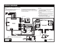
WIRING DIAGRAM
Wall Mount Air Handler (8,10KW)
3. The transformer may have a dual voltage primary
tap. Match the tap position with the supply voltage used.
4. If the Internal wiring is replaced, use only 105°C copper
wire of the same gauge.
NOTES:
1. The blower motor speed tap connection may not be as
shown. See the Installation Instructions.
2. Disconnect all power before servicing.
Remarques
1. Le connecteur de vitesse du moteur du ventilateur
peut différer de l’illustration. Consultez les
Instructions d’installation.
2. Débranchez toutes les sources d’alimentation avant
l’entretien.
3. Le transformateur peut avoir un robinet principal à
double tension. Agencez la position du robinet au
type de tension de l’installation.
4. Si le câblage interne est remplacé, utilisez seulement
un fil de cuivre 105° C du même gabarit.
711242B
(Replaces 711242A)
CONTROL
BOARD
R
C
L2
L1
HEAT
COOL
EAC
L1
L2
HEATER
Y
W
G C
R
TRANSFORMER
24V
230V
LIMIT
ELEMENT RELAY
ELEMENT RELAY
ELEMENT
ELEMENT
SUPPLY VOLTAGE
NOTE:
1. B6BW-030: USE 3-SPEED MOTOR CONNECTION AS ABOVE.
2. B6BW-018 AND B6BW-024: USE 2-SPEED MOTOR CONNECTION.
MOTOR CONNECTION
SEE NOTE
PSC
MOTOR
(3-SPEED)
1
3
5
2
4
6
1=COM
2=CAP.
3=CAP.
4=HI
5=MED
6=LOW
CAP.
2
1
4
3
CIRCUIT
BREAKER
GRAY
ORANGE
2-SPEED
MTR
1=COM
2=CAP.
3=CAP.
4=HI
5=LOW
1
3
5
2
4
6
CAP.
L2
HEAT
COOL
GRAY
COM
NO
COM
NO
BLUE
RED
WHITE
BLACK
GRAY
YELLOW
WHITE
GRAY
RED
GREEN
CONNECTOR
RED
WHITE
BROWN
BROWN
BLACK
BLACK
RED
RED
RED
RED
BLACK
BLACK
BLACK
WHITE
HARNESS
HARNESS
BLACK
HARNESS
CONNECTOR
WHITE
RED
BLACK
BROWN
BROWN
BLWDTC
R
BLACK
IF BOARD
EQUIPPED
WITH
BLWDTC
TERMINAL
-
 1
1

dans d''autres langues
- English: Maytag B6BW Product information
Documents connexes
-
Maytag MB7BM Information produit
-
Maytag B6BW Information produit
-
-
-
-
-
-
Miller B6BV Information produit
-
Maytag B6VMAI Information produit
-