Lennox Crestline LSBV-3628MP Manuel utilisateur
- Catégorie
- Cheminées
- Taper
- Manuel utilisateur

1
NOTE: DIAGRAMS & ILLUSTRATIONS NOT TO SCALE.
Do not store or use gasoline or other flammable
vapors or liquids in the vicinity of this or any other
appliance.
What to do if you smell gas:
• DO NOT light any appliance.
• DO NOT touch any electrical switches, do not
use any phone in your building.
• Immediately call your gas supplier from a
neighbor’s phone. Follow your gas suppliers
instructions.
• If your gas supplier cannot be reached, call the
fire department.
Installation and service must be performed by a
qualified installer, service agency or the gas
supplier.
INSTALLATION
INSTRUCTIONS
CRESTLINE™ SERIES
B-VENTED GAS APPLIANCES
P/N 850,042M REV. A 12/2008
MODELS
Millivolt Models Electronic Models
LSBV-3628MN LSBV-3628EN
LSBV-3628MP LSBV-3628EN-H
LSBV-3628MN-H LSBV-4228EN
LSBV-3628MP-H LSBV-4228EN-H
LSBV-4228MN
LSBV-4228MP
LSBV-4228MN-H
LSBV-4228MP-H
OTL Report No. 116-F-45-5
WARNING: IF THE INFORMATION IN THIS MANUAL
IS NOT FOLLOWED EXACTLY, A FIRE OR EXPLO-
SION MAY RESULT CAUSING PROPERTY DAM-
AGE, PERSONAL INJURY OR LOSS OF LIFE.
This appliance may be installed in an aftermarket perma-
nently located, manufactured home (USA only) or mobile
home, where not prohibited by local codes. This appliance
is only for use with the type of gas indicated on the rating
plate. This appliance is not convertible for use with other
gases, unless a certified kit is used.
In the Commonwealth of Massachusetts & New York:
• Installation must be performed by a licensed plumber or
gas fitter.
See Table of Contents for location of additional New York
& Commonwealth of Massachusetts requirements.
INSTALLER: Leave this manual with the appliance.
CONSUMER: Retain this manual for future reference.
US
Portland
Ne pas entreposer ni utiliser d’essence ni d’autre
vapeurs ou liquides inflammables dans le voisinage
de cet appareil ou de tout autre appareil.
QUE FAIRE SI VOUS SENTEZ UNE ODEUR DE GAZ:
•Ne pas tenter d’allumer d’appareil.
•Ne touchez à aucun interrupteur. Ne pas vous
servir des téléphones se trouvant dans le bátiment
où vous vous trouvez.
•Appelez immédiatement votre fournisseur de gaz
depuis un voisin. Suivez les instructions du
fournisseur.
•Si vous ne pouvez rejoindre le fournisseur de gaz,
appelez le service des incendies.
L’installation et l’entretien doivent être assurés par
un installeur ou un service d’entretien qualifié ou par
le fournisseur de gaz.
INSTALLATEUR: Laissez cette notice avec l’appareil.
CONSOMMATEUR: Conservez cette notice pour
consultation ultérieure.
AVERTISSEMENT: ASSUREZ-VOUS DE BIEN SUIVRE
LES INSTRUCTIONS DONNÉES DANS CETTE NOTICE
POUR RÉDUIRE AU MINIMUM LE RISQUE D’INCENDIE
D’EXPLOSION OU POUR ÉVITER TOUT DOMMAGE
MATÉRIEL, TOUTE BLESSURE OU LA MORT.
LENNOX HEARTH PRODUCTS
A French manual is available upon request. Order P/N 506223-07.
Ce manuel d’installation est disponible en francais, simplement en faire
la demande. Numéro de la pièce 506223-07.

2NOTE: DIAGRAMS & ILLUSTRATIONS NOT TO SCALE.
TABLE OF CONTENTS
Packaging........................................ page 2
Introduction..................................... page 2
Massachusetts and New York
Requirements ................................ page 2
General Information......................... page 2
Location .......................................... page 3
Appliance Specifications.................. page 4
Clearances ....................................... page 4
Gas Vent Rule.................................. page 4
Framing Specifications .................... page 5
Assembly Steps............................... page 5
Installation....................................... page 6
Vent System Installation.................. page 7
Field Wiring ..................................... page 7
Connecting Gas Line........................ page 8
Outside Air Kit Installation ............... page 8
Log and Rockwool Installation ........ page 9
Appliance Operation ........................ page 10
Manual Limit Switch........................ page 10
Millivolt Appliance Checkout............ page 11
Electronic Appliance Checkout......... page 11
Adjustments .................................... page 11
Finishing Requirements................... page 12
Cold Climate Insulation.................... page 12
Installation Accessories................... page 12
Gas Conversion Kits.................. page 14
GENERAL INFORMATION
Note: Installation and repair should be per-
formed by a qualified service person. The appli-
ance should be inspected annually by a quali-
fied professional service technician. More fre-
quent inspections and cleanings may be re-
quired due to excessive lint from carpeting,
bedding material, etc. It is imperative that the
control compartment, burners and circulating
air passage ways of the appliance be kept clean.
S'assurer que le brùleur et le compartiment des
commandes sont propres. Voir les instruc-
tions d'installation et d'utilisation qui
accompagnent l'apareil.
Provide adequate clearances around air open-
ings and adequate accessibility clearance for
service and proper operation. Never obstruct
the front openings of the appliance.
DO NOT ATTEMPT TO ALTER OR MODIFY
THE CONSTRUCTION OF THE APPLIANCE OR
ITS COMPONENTS. ANY MODIFICATION OR
ALTERATION MAY VOID THE WARRANTY,
CERTIFICATION AND LISTINGS OF THIS UNIT.
These appliances are designed to operate on
natural or propane gas only. The use of other fuels
or combination of fuels will degrade the perfor-
mance of this system and may be dangerous.
Input of appliance are 45,000 BTU/HR for Pro-
pane models and 50,00 BTU/HR for Natural Gas
models.
INTRODUCTION
The millivolt appliances are designed to oper-
ate on either natural or propane gas. A millivolt
gas control valve with piezo ignition system
provides safe, efficient operation.
The electronic appliances are designed to op-
erate on either natural or propane gas. An
electronic intermittent pilot system provides
safe, efficient operation. External electrical
power is required to operate these units.
These appliances comply with National Safety
Standards and are tested and listed by Omni-
Test Laboratories (Report No. 116-F-45-5) to
ANSI Z21.50b (in Canada, CSA-2.22b), and
CAN/CGA-2.17-M91 in both USA and Canada,
as vented gas fireplaces.
Installation must conform to local codes. In
the absence of local codes, installation must
comply with the current National Fuel Gas
Code, ANSI Z223.1 (NFPA 54). (In Canada, the
current CAN/CGA B149 installation code.) Elec-
trical wiring must comply with local codes. In
the absence of local codes, installation must
be in accordance with the National Electrical
Code, NFPA 70 - (latest edition). (In Canada,
the current CSA C22.1 Canadian Electric Code.)
These Crestline series appliances have been
designed, tested and listed for use with Security
Chimney's 10" B-vent system. Refer to page 12
for a complete listing of the 10" B-vent compo-
nents available for use with these models.
3 - one envelope containing the literature
package which consists of the homeowner's
manual, installation instructions, and war-
ranty; envelope is located in the control area.
WARNING: THESE FIREPLACES ARE
VENTED DECORATIVE GAS APPLIANCES.
DO NOT BURN WOOD OR OTHER MATE-
RIAL IN THESE APPLIANCES.
WARNING: IMPROPER INSTALLATION,
ADJUSTMENT, ALTERATION, SERVICE
OR MAINTENANCE CAN CAUSE INJURY
OR PROPERTY DAMAGE. REFER TO THIS
MANUAL. FOR ASSISTANCE OR ADDI-
TIONAL INFORMATION CONSULT A
QUALIFIED INSTALLER, SERVICE
AGENCY OR THE GAS SUPPLIER.
PACKAGING
The assembled vented gas fireplace is pack-
aged with:
1 - one foam packaged log set located in fire-
box area.
2 - one bag of glowing embers (rockwool)
located in the bottom compartment.
Massachusetts:
Installation of these fireplaces are approved
for installation in the US state of Massachu-
setts if the following additional requirements
are met-
• Installation and repair must be done by a
plumber or gas fitter licensed in the Common-
wealth of Massachusetts.
• The flexible gas line connector used shall not
exceed 36 inches (92 centimeters) in length.
• The individual manual shut-off must be a T-
handle type valve.
New York City, NY:
Installation of these fireplaces are approved
for installation in New York City in the US state
of New York, if the following additional re-
quirements are met-
• An outside air kit (FOAK-4 or FOAK-4LD)
must be installed.
Massachusetts And New York City, NY
Requirements
These appliances are approved for installation
in the following USA locations listed in the
following:
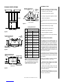
Gas Orifice Size
Type Elevation
0 - 4500'
(0 - 1370 m)
0 - 4500'
(0 - 1370 m)
Natural Propane
#26 #45
#45
LSBV-3628
LSBV-4228
#26
This manual is part of a set of two supporting
this product. Refer to manual 875,035M for
Care & Operations.
Please read and understand these
instructions before beginning your
installation.

3
NOTE: DIAGRAMS & ILLUSTRATIONS NOT TO SCALE.
Carbon Monoxide Poisoning: Early signs of
carbon monoxide poisoning are similar to the
flu with headaches, dizziness and/or nausea. If
you have these signs, obtain fresh air immedi-
ately. Turn off the gas supply to the appliance
and have it serviced by a qualified profes-
sional, as it may not be operating correctly.
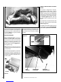
In selecting the location, the aesthetic and func-
tional use of the appliance are primary concerns.
However, vent system routing to the exterior and
access to the fuel supply are also important. Due
to high temperatures the appliance should be
located out of traffic and away from furniture and
draperies. Consideration should be given to traf-
fic ways, furniture, draperies, etc., due to el-
evated surface temperatures. The location should
also be free of electrical, plumbing or other
heating/air conditioning ducting.
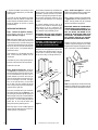
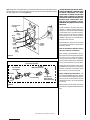
These appliances are equipped with an inte-
gral combustion air door and actuator arm.
Combustion air kits are optional and must be
installed before removing the securing screw
allowing the movement of the combustion
air actuator arm (see Step 7 on page 8).
Test gage connections are provided on the front
of the millivolt gas control valves (identified
OUT for the manifold side and IN for inlet
pressure side.
Minimum inlet gas pressure to the appliance is
5.0 inches water column (1.24 kPa) for natural
gas and 11 inches water column (2.74 kPa) for
propane for the purpose of input adjustment.
Maximum inlet gas supply pressure to the
appliance is 10.5 inches water column (2.61kPa)
for natural gas and 13.0 inches water column
(3.23 kPa) for propane. The appliance must
be isolated from the gas supply piping sys-
tem (by closing its individual manual shut-
off valve) during any pressure testing of the
gas supply piping system at test pressures
equal to or less than 1/2 psig (3.5) kPa).
LOCATION
Nominal operating pressures for the manifold
side of the gas control system are; 3.5 inches
water column (0.87 kPa) for natural gas mod-
els and 10 inches water column (2.49 kPa) for
propane gas models.
Do not use these appliances if any part has been
under water. Immediately call a qualified, pro-
fessional service technician to inspect the ap-
pliance and to replace any parts of the control
system and any gas control which have been
under water.
Ne pas se servir de cet appareil s'il a été plongé
dans l'eau, complètement ou en partie. Appeler
un technicien qualifié pour inspecter l'appareil et
remplacer toute partie du système de contrôle et
toute commande qui ont été plongés dans l'lau.
This appliance may be installed in an after-
market permanently located, manufactured
home (USA only) or mobile home, where not
prohibited by local codes. This appliance is
only for use with the type of gas indicated
on the rating plate. This appliance is not con-
vertible for use with other gases, unless a
certified kit is used.
Cet appareil peut être installé dans un maison
préfabriquée (É.-U. seulement) ou mobile déjà
installée à demeure si les réglements locaux
le permettent. Cet appareil doit être utilisé
uniquement avec les types de gaz indiqués
sur la plaque signalétique. Ne pas l'utiliser
avec d'autres gaz sauf si un kit de conversion
certifié est installé.
Typical Locations
Figure 1
The appliance and its individual shut-off valve
must be disconnected from the gas supply
piping system during any pressure testing of
that system at pressures in excess of 1/2 psig
(3.5 kPa).
These appliances must not be connected to a
chimney or flue serving a separate solid fuel
burning appliance.
Do not place clothing or other materials on or
near this appliance.
WARNING: CHILDREN AND ADULTS
SHOULD BE ALERTED TO THE HAZARDS
OF HIGH SURFACE TEMPERATURES. USE
CAUTION AROUND THE APPLIANCE TO
AVOID BURNS OR CLOTHING IGNITION.
YOUNG CHILDREN SHOULD BE CARE-
FULLY SUPERVISED WHEN THEY ARE IN
THE SAME ROOM AS THE APPLIANCE.
WARNING: DO NOT PLACE CLOTHING
OR OTHER FLAMMABLE MATERIALS
ON OR NEAR THIS APPLIANCE.
AVERTISSEMENT: SURVEILLER LES
ENFANTS. GARDER LES VÊTEMENTS,
LES MEUBLES, L'ESSENCE OU AUTRES
LIQUIDES À VAPEUR INFLAMMABLES
LIN DE L'APPAREIL.
WARNING: THIS APPLIANCE MAY ONLY
BE FITTED WITH DOORS CERTIFIED FOR
USE WITH THE APPLIANCE.
WARNING: FAILURE TO COMPLY WITH
THE INSTALLATION AND OPERATING IN-
STRUCTIONS PROVIDED IN THIS DOCU-
MENT WILL RESULT IN AN IMPROP-
ERLY INSTALLED AND OPERATING AP-
PLIANCE, VOIDING ITS WARRANTY. ANY
CHANGE TO THIS APPLIANCE AND/OR
ITS OPERATING CONTROLS IS DANGER-
OUS. IMPROPER INSTALLATION OR USE
OF THIS APPLIANCE CAN CAUSE SERI-
OUS INJURY OR DEATH FORM FIRE,
BURNS, EXPLOSION OR CARBON MON-
OXIDE POISONING.
WARNING: B-VENT APPLIANCES ARE
NOT DESIGNED TO OPERATE IN NEGA-
TIVELY PRESSURED ENVIRONMENTS
(PRESSURE WITHIN THE HOME IS LESS
THAN PRESSURES OUTSIDE). SIGNIFI-
CANT NEGATIVELY PRESSURED ENVI-
RONMENTS CAUSED BY WEATHER,
HOME DESIGN, OR OTHER DEVICES MAY
IMPACT THE OPERATION OF THESE AP-
PLIANCES. NEGATIVE PRESSURES MAY
RESULT IN POOR FLAME APPEARANCE,
SOOTING, DAMAGE TO PROPERTY AND/
OR SEVERE PERSONAL INJURY. DO NOT
OPERATE THESE APPLIANCES IN NEGA-
TIVELY PRESSURED ENVIRONMENTS.

4NOTE: DIAGRAMS & ILLUSTRATIONS NOT TO SCALE.
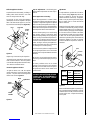
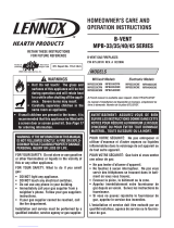
Venting
Gas Vent Rule – Gas vent caps are not permit-
ted within 8 feet (2.4 mm) of a vertical wall or
similar obstruction. Gas vent caps that are
located 8' or more from a portion of a building
which extends at an angle greater than 45°
upward from the horizontal may terminate in
accordance with
Table 1 (Figure 3)
, provided
that in no case shall any discharge opening on
the cap be less than 2' (610 mm) horizontally
from the roof surface (National Fuel Gas Code
ANSI Z223.1 (NFPA 54) 7.6.2) (CAN/CGA B149).
CLEARANCES
Minimum clearance to combustibles for the ap-
pliance is as follows: sides and back - 3/8" (9.52
mm), floor - 0" (0 mm), adjacent wall - 0" (0 mm),
ceiling - 37-1/2" (953 mm).
APPLIANCE SPECIFICATIONS
Figure 2 Table 1
Note: Venting terminals shall not be recessed
into a wall or siding.
Flat to 6/12 1' 0" 0.3
Over 7/12 to 9/12 2' 0" 0.6
Over 10/12 to 12/12 4' 0" 1.2
Over 13/12 to 16/12 6' 0" 1.8
Over 17/12 to 21/12 8' 0" 2.4
Roof Slope
Minimum Height
from Roof to Lowest
Discharge Opening
Feet Meters
Roof Pitch is X/12
12 X
Minimum Height from Roof
to Lowest Discharge Opening
The appliance should be mounted on a fully
supported base extending the full width and
depth of the unit. The appliance may be located
on or near conventional construction materi-
als. However, if installed on combustible mate-
rials, such as carpeting, vinyl tile, etc., a metal
or wood barrier covering the entire bottom
surface must be used.
These appliances may be used for bedroom
installations in the United States and are listed
accordingly. These units may not be installed
in bedrooms in Canada.
Figure 3
Front View
12-15/32
28-15/32 41-5/16
47-9/32
52-11/32
LSBV-36: 41-3/4
LSBV-42: 47-3/4
7-3/32
5-3/4 LSBV-36: 37
LSBV-42: 43
Left Side View
1-7/16
8-7/8
Right Side View
7-7/16
15-27/32
1-25/32
4-13/32
16-1/16 2-9/32
Top View
LSBV-36: 23-1/2
LSBV-42: 29-1/2
20-1/32
8-15/32
19/32
Gas Line
Or Switch
Wire Outlet
Gas Line
Or Switch
Wire Outlet
Combustion
Air Inlet
Junction
Box
Location

5
NOTE: DIAGRAMS & ILLUSTRATIONS NOT TO SCALE.
FRAMING SPECIFICATIONS
Figure 4
Figure 5
Figure 6
Framing Dimensions
ASSEMBLY STEPS
The typical sequence of installation follows,
however, each installation is unique resulting
in variations to those described.
1. Construct the appliance framing.
2. Route gas supply line to appliance location.
3. Position the appliance.
4. Install the vent system and exterior termina-
tion.
5. Field wire and install operating control switch.
6. Make connection to gas supply.
7. Install (optional) outside Air Kit.
8. Install the logs and rockwool.
9. Checkout appliance operation.
10. Adjust burner to ensure proper flame ap-
pearance.
PRE-INSTALLATION NOTES
The fireplace may be installed directly on a
combustible floor or raised on a platform of an
appropriate height. Do not place fireplace on
carpeting, vinyl or other soft floor coverings. It
may, however, be placed on flat wood, ply-
wood, particle board or other hard surfaces. Be
sure fireplace rests on a solid continuous floor
or platform with appropriate framing for sup-
port and so that no cold air can enter the room
from under the fireplace.
The fireplace may be positioned and then the
framing built around it, or the framing may be
constructed and the fireplace positioned into
the opening.
Usually, no special floor support is needed for
the fireplace, however, to be certain:
1. Estimate the total weight of the fireplace
system and surround materials such as brick,
stone, etc., to be installed.
2. Measure the square footage of the floor
space to be occupied by the system, surrounds
and hearth extensions.
3. Note the floor construction, i.e. 2 x 6’s, 2 x
8’s or 2 x 10’s, single or double joists, type and
thickness of floor boards.
Note: All framing dimensions calcu-
lated for 1/2" dry wall at the appliance
face. If sheathing the chase or finish-
ing with other thickness materials, cal-
culations will need to be made.
Figure 7
Fireplace Opening Width
42-1/4"
(1073 mm)
A
B
C
D
E
48-1/4"
(1226 mm)
52-1/2"
(1344 mm) 52-1/2"
(1344 mm)
23-9/16"
(599 mm) 29-9/16"
(751 mm)
11-1/4"
(286 mm) 14-1/4"
(362 mm)
63-1/2"
(1613 mm) 69-1/2"
(1765 mm)
LSBV-3628 LSBV-4228
31-3/4"
(807 mm)
F
G
H
J
K
34-3/4"
(883 mm)
20-1/2"
(521 mm) 20-1/2"
(521 mm)
4"
(102 mm) 4"
(102 mm)
7-1/2"
(190 mm) 7-1/2"
(190 mm)
44-3/16"
(1122 mm) 49-1/8"
(1248 mm)
Corner Installation
KD
C
A
E
GF
Back Wall of Chase/Enclosure
Including Finishing Materials
if any
Rough
Framing Face
(Unfinished Shown)
FOAK-4
Combustion
Air Kit
AHH
C
G
Inside Chase
Back Wall of Chase/Enclosure
Including Finising Materials
if any
Rough
Framing Face
(Unfinished Shown)
FOAK
Combustion
Air Kit
FOAK
Combustion
Air Kit
A
Outside Chase
G
C
J
Back Wall of Chase/Enclosure
Including Finishing Materials
if any
Rough Framing Face
(Unfinished Shown)
Optional Locations
FATO Adapter
(Optional)
Header
B
A
Fireplace Framing

6NOTE: DIAGRAMS & ILLUSTRATIONS NOT TO SCALE.
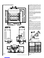
Step 3. Position the Appliance - Slide the
fireplace into prepared framing or position fire-
place in its final position and frame later.
Refer to fireplace drawings and specifications
on pages 4 and 5 for framing dimensions and
details. Framing header may be positioned
directly on the fireplace top spacers.
IMPORTANT: UNDER NO CIRCUMSTANCES
CAN THE FIREPLACE TOP SPACERS
(refer to
FIGURE 2 )
BE REMOVED OR MODIFIED, NOR
MAY YOU NOTCH THE HEADER TO FIT
AROUND OR BE INSTALLED LOWER THAN
THE SPACERS. THE HEADER MAY BE IN DI-
RECT CONTACT WITH THE TOP SPACERS
BUT MAY NOT BE SUPPORTED BY THEM.
Fireplace should be secured to side framing
members using the full length 1/2 inch nailing
flanges that are integral to the appliance at each
side. Use 6d nails or equivalent
(Figure 9 )
.
All appliances are equipped with a gas flex line
and shutoff valve attached directly to the gas
control valve. To quickly and easily complete
the gas line routing, use the gas flex line kit.
4. Use this information and consult your local
building code to determine if you need addi-
tional support.
If you plan to raise the fireplace and hearth
extension, build the platform assembly then
position fireplace and hearth extension on top.
Secure the platform to the floor to prevent
possible shifting.
INSTALLING THE FIREPLACE
Step 1. Construct the Appliance Framing -
Frame appliance enclosure as illustrated in
Figures 4 through 7
on page 5.
Note: The framed depth, 20-1/2" (521 mm)
from a framed wall, must always be measured
from a finished surface. If a wall covering such
as drywall is to be attached to the rear wall, then
the 20-1/2" (521 mm) must be measured from
the drywall surface. It is important that this
dimension be exact.
If the appliance is to be elevated above floor
level, a solid continuous platform must be
constructed.
The header may rest on the top metal spacers,
but must not be notched to fit around them.
Consult all local codes.
Step 2. Route Gas Supply Line - Route gas
line
(Figure 8 )
using techniques and materi-
als prescribed by local and/or national codes.
It is recommended that a gas line of 1/2" or
greater diameter be used to allow full gas
volume to the fireplace. Undue pressure loss
will occur if the pipe is too small. The appli-
ance, as set up at the factory, is best suited
for use with a gas line routed from the left
side. The gas line may however be alternately
routed from the right side.
This unit is provided with a gas line/switch
wire outlet at both sides (see
Figure 2
). The
gas line may be routed through this opening at
either the right or left side. Route the Millivolt
switch wire through the opening opposite form
the gas line. To avoid cutting the Millivolt
switch wire, do not route the switch wire
through the opening with the gas line.
When rigid pipe is used, an ANSI approved
manual shut-off valve and union must be in-
stalled upstream of the fireplace.
IMPORTANT: HOLD GAS VALVE SECURELY
TO PREVENT MOVEMENT WHEN CONNECT-
ING TO INLET GAS LINE
An external regulator must be used on all
propane (L.P.G.) heaters to reduce the supply
tank pressure to 13" w.c. (maximum). Any
copper tubing used to supply propane (L.P.G.)
from the tank must be internally tinned.
Note: The nailing flanges and the area directly
behind the nailing tabs are exempt from the
clearances described on the fireplace clearance
label.
Figure 8
Figure 9
10-1/2"
(269 mm)
3-1/2"
(79 mm)
RIGHT
SIDE
LEFT
SIDE
7-1/4"
(184 mm)
3-1/2"
(79 mm)
WARNING: CONNECTING DIRECTLY TO
AN UNREGULATED PROPANE (L.P.G.)
TANK MAY CAUSE AN EXPLOSION.
6d Nail or
Equivalent
Ensure that a sediment trap is installed in the
existing gas line, if not, install a sediment trap
upstream to prevent moisture and contami-
nants from passing through trap to the appli-
ance controls and burners. Failure to do so
could prevent the appliance from operating
reliably.

7
NOTE: DIAGRAMS & ILLUSTRATIONS NOT TO SCALE.
Figure 10
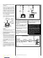
Step 4. Install the Vent System & Exterior
Termination -
Slip a 10" (254 mm) B-Vent system over the
appliance collar (
Figure 10
) and secure
with four sheetmetal screws (# 8 or larger).
Minimum overall height of the vent system
and appliance must be 12' (3.66 m) vertical
(no offset) or 17' (5.18 m) when an offset up
to 45 degrees from the vertical is used. The
lower part of the offset must not begin less
than 3' (0.914 m) above the top of the
fireplace
(see Figure 11 )
.
Maximum overall height of the vent system and
appliance should not exceed 40 feet (12.19m).
Figure 11
Install the B-vent system in accordance with
the vent manufacturer's instructions.
CAUTION: THIS APPLIANCE CANNOT BE
VENTED HORIZONTALLY.
Note: Refer to the vent manufacturers installa-
tion instructions for variations of venting tech-
niques. If common venting of several units is
contemplated, it should be discussed with an
architect and the local Building Department.
Step 5. Field Wiring – Refer to Section A for
millivolt appliances and Section B for electronic
appliances.
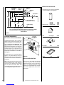
A. Millivolt Wiring – Units are fitted at the
factory with an SIT millivolt gas control valve.
The valve has been tested with and approved
for use with these appliances and is listed
accordingly. Refer to
Figure 12
for the wiring
diagram.
12 ft.
Minimum 17 ft.
Minimum
45 degrees
max.
3 ft.
Minimum
to Offset
The gas valve has been set in place and has been
pre-wired at the factory. Locate the wall switch
(not provided) or optional remote control in the
desired location and connect the millivolt wire
(see Figure 12 ).
CAUTION: DO NOT CONNECT THE WALL
SWITCH TO A 120V POWER SUPPLY.
Note: The ends of the 18' coiled wire must be
connected to the wall switch (not supplied) for
the appliance to operate.
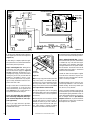
B. Electronic Wiring – The electronic appli-
ance must be connected to the main power
supply. To install, route a 3-wire 120V 60Hz
power supply to the appliance junction box
and ground.
IMPORTANT: Ground lead must be con-
nected to the green screw located on
the outlet box. See
Figure 16
on page 9.
Failure to do so will result in a potential
safety hazard. The appliance must be
electrically grounded in accordance with
local codes or, in the absence of local
codes, the National Electrical Code,
ANSI/NFPA 70-(latest edition). (In
Canada, the current CSA C22-1 Cana-
dian Electrical Code.)
Figure 12
BLACK BLACK
DAMPER SWITCH LIMIT SWITCH
MILIVOLT WIRING DIAGRAM
TH
TP TP TH
THERMOPILE
WALL MOUNTED
ON/OFF SWITCH
GAS VALVE
BLACK
WHITE
10”
Type B-Vent
Flue Outlet
Collar
Securing
Screws
Locate and install a low voltage (24V) wall
switch (not supplied) in the desired location.
Connect the low voltage wire to this switch
(
see Figure 13
on Page 8)
.

8NOTE: DIAGRAMS & ILLUSTRATIONS NOT TO SCALE.
Figure 14
1. Route a 3-wire 120V 60Hz power supply line
to the appliance junction box wires and ground
(Figures 13 ).
2. After wiring is complete, replace the appli-
ance junction box cover and secure with the hex
head screws previously removed.
Step 6. Connecting Gas Line – Make gas line
connections. All codes require a shut-off
valve mounted in the supply line.
Figure 16
on page 9
illustrates the method for con-
necting the gas supply. The flex-line method
utilizing the gas flex line provided with the
appliance is acceptable in the U.S., how-
ever, Canadian requirements vary depend-
ing on locality. Installation must be in com-
pliance with local codes.
The gas control valve is located in the lower
control compartment. To access the valve
remove the refractory access panel and set
aside
(Figure 14 ).
The control valve has a
3/8" (10 mm) NPT thread inlet port.
Secure all joints tightly using appropriate
tools and sealing compounds (ensure pro-
pane resistant compounds are used in pro-
pane applications).
Turn on gas supply and test for gas leaks,
using a gas leak test solution (also referred to
as bubble leak solution).
Refractory
Access Panel
SIT Valve
Shown
Note: Using a soapy water solution (50% dish
soap, 50% water) is an effective leak test
solution but it is not recommended, because
the soap residue that is left on the pipes/
fittings can result in corrosion over time. Never
use an open flame to check for leaks.
A. Light the appliance (refer to the lighting
instructions label in the control compartment
or in the Homeowner's Care and Operation
Instructions).
B. Brush all joints and connections with the
gas leak test solution to check for leaks. If
bubbles are formed, or gas odor is detected,
turn the gas control knob to the “OFF” posi-
tion. Either tighten or refasten the leaking
connection and retest as described above.
C. When the gas lines are tested and leak free,
be sure to rinse off the leak testing solution.
Step 7. Optional Outside Air Kits – Combus-
tion (outside make-up air) kits, Model FOAK-4
or FAOK-4LD, may used with these appli-
ances. Refer to the installation instructions
packaged with the air kits for specific installa-
tion information. The outside air kit must be
installed before the fireplace is framed and
enclosed in the finished wall.
Outside air drawn into the fireplace supplies
air to the fire for combustion. Only one com-
bustion air duct on the right side of the fire-
place is necessary if installed.
If additional length of duct is necessary, pur-
chase locally available U.L. Class 0 or Class 1
metallic ducting. The duct may extend up to
50' (15.24 m) in any direction.
There is one hand operated air gate shut-off,
for utside make-up air, located at the right side
of the fireplace opening behind the screen. To
open, lift and pull the handle out. The combus-
tion air damper should be
open when the
fireplace is in use
and, to prevent outside air
from entering your home, fully closed when
the fireplace is not in operation.
WHITE
DAMPER SWITCH LIMIT SWITCH
CONNECTOR
BLACK BLACK
ELECTRONIC WIRING DIAGRAM
BK
W
24 V.
TRANSF
120 V.
ELECTRONIC IGNITION
CONTROL BOARD
WALL MOUNTED
ON/OFF SWITCH
PILOT BURNER
IGNITER-SENSOR
ASSEMBLY
GAS VALVE
EV2 EV1
GROUND
CONNECTOR
GREEN LED
WHITE
ORANGE
BLACK
PURPLE
GREEN
BLUE
BLACK
WHITE
Junction Box
White
Green
Red
Black
Neutral
Side of
Receptacle
Green
Ground
Screw Hot
Side of
Receptacle
Ta b
Broken
Plug blower
into this
receptacle
Tab Intact
120 VAC - Black
n
e
e
r
G-dn
u
o
r
Ge
ti
h
W
-
lar
t
u
e
N
Figure 13

9
NOTE: DIAGRAMS & ILLUSTRATIONS NOT TO SCALE.
Figure 15
Note: Supply wires may be alternatively connected to the outlet using the screw terminals, however
the black supply wire must be wired to a terminal that is opposite (across the outlet) the point where
the white supply wire is connected (Figure 15 ).
Figure 16
CAUTION: NEVER LOCATE INLET OF AN OUT-
SIDE AIR HOOD WHERE IT CAN BE BLOCKED
BY SHRUBS, SNOW DRIFTS, ETC. NEVER
LOCATE INLET IN GARAGE OR ANY AREA
WHERE THERE IS ANOTHER FUEL BURNING
APPLIANCE OR PRODUCTS EMITTING COM-
BUSTIBLE GASES SUCH AS PAINT, GASO-
LINE, ETC. IN COLD CLIMATES, IT IS REC-
OMMENDED THE COMBUSTION AIR DUCT BE
INSULATED.
Outside combustion air ducting may be run
upwards or vertically through framing and
ceiling joists, with the hood installed through
an outside wall and 3' (1 m) below the termi-
nation. Ducting may also be run downward
through floor joists and under the home to a
ventilated crawlspace not considered part of
the living area of the home.
After installing the outside air kit, remove the
cover from the shut off lever in the left side of
the firebox opening.
Note: Do not terminate combustion air kit in
attic space under any circumstances.
After completing the installation of the op-
tional combustion air vent system the actuator
arm must be put in service and tested to
ensure proper operation before completing
any enclosure around the firebox. Failure to do
so may result in extensive and costly rework.
Operate the actuator through several cycles
including the closed position. Ensuring proper
operation and freedom of movement. Return
the actuator arm to the closed position.
Step 8. Installing Logs and Rockwool – The
logs are packaged within the firebox. Remove
the rockwool from the packaging and tear into
dime size pieces (see Homeowners Care and
Operation Instructions). Do not use more than
is necessary.
Displace Lava Rock to the center of the burner
pan when removing and reinstalling the burner
tube.
1/2" x 3/8" Flare
Shut-Off Valve
3/8" Flex Tubing
Gas Flex Line (provided)
Gas Stub
3/8" NPT Flare
Fitting (Remove
Before Hard Piping)
Gas Valve
(Millivolt or Electronic)
White
(Supply)
Black
(Supply)
Bipolar
Terminal
Screw
120 Vac
60 Hz
Green Wire Ground
Connection
Red
(Supply)
120 Vac
60 Hz
120 Vac
60 Hz

10 NOTE: DIAGRAMS & ILLUSTRATIONS NOT TO SCALE.
Figure 17
Figure 18
Refer to the Homeowners Care and Operation
Instructions for detailed log description and
placement instructions. Log set shown in this
document
(Figure 17 )
is typical, installation
of all sets are similar.
APPLIANCE OPERATION
Step 9. Checking the System – With gas line
installed run initial system checkout before
closing up the front of the unit. Follow the pilot
lighting instructions provided in the
Homeowner's Care and Operation Instructions.
For piezo ignitor location see
Figure 18
(mil-
livolt appliances only).
Note: Instructions are also found on the pull
out lighting instructions label attached to the
gas control valve.
When first lighting the appliance, it will take a
few minutes for the line to purge itself of air.
Once purging is complete, the pilot and burner
will light and operate as indicated in the in-
struction manual.
MANUALLY-RESET BLOCKED FLUE SAFETY
SWITCH
This appliance is equipped with a manually-
reset blocked flue safety switch. Refer to
Figure 19
for its location. If during appliance
operation, the flame goes out (independently
of the burner on/off wall switch), it may be due
to the operation of this safety limit switch.
First allow the appliance to cool. Then reset
the safety switch by pushing the red reset
button.
This reset button is located on the back of the
limit switch, between the wire terminals (
see
Detail A of Figure 19
).
The appliance should then relight and remain
lit. If this does not occur, turn off the appli-
ance and call a qualified service technician.
Figure 19
Detail A
Manual Reset
Limit Switch
Lintel
Extension Right Side
Refractory Panel
Reset
Button
Wire
Terminals
Subsequent lightings of the appliance will
not require such purging. Inspect the pilot
flame (remove logs, if necessary, handling
carefully).
Piezo
Ignitor
SIT Valve

11
NOTE: DIAGRAMS & ILLUSTRATIONS NOT TO SCALE.
Figure 22
Adjustment
To adjust the flame, position the air shutter to
the nominal setting
(Figure 22 ).
Allow the
burner to operate for at least 30 minutes.
Observe the flame continuously. If it appears
weak or sooty as previously described, adjust
the air shutter open or closed until desired
effect is achieved.
Note: If the flame still appears anemic with the
air shutter closed all the way (usually a result of
lengthy vertical venting runs), turn off the appli-
ance, turn off the gas supply, wait for the parts
to cool and access the air shutter. The shutter
is prevented from actually closing by a tab that
is bent over into the opening. Remove this
obstruction by bending back. Reassemble and
restart the appliance and after 24 minutes
reobserve the flame. Adjust the air shutter as
described.
Figure 21
Replace logs if removed for pilot inspection.
To light the burner; rotate the gas valve control
knob counterclockwise to the “ON” position
(“ON” will be to the right hand side of the valve).
Turn “ON” the remote wall switch.
Electronic Appliance Checkout
To light the burner, turn ‘ON’ the optional
remote wall switch. Ensure the ignitor lights
the pilot. The pilot flame should engulf the
flame rod as shown in
Figure 21.
Step 10. Adjustments – The following para-
graphs address adjustment concerns and pro-
cedures.
Flame Appearance and Sooting
Proper flame appearance is a matter of taste.
Generally most people prefer the warm glow of
a yellow to orange flame. Appliances operated
with air shutter openings that are too large, or
with long vertical vent runs, will exhibit flames
that are blue and transparent. These weak, blue
and transparent flames are termed anemic.
If the air shutter opening is too small sooting
may develop. Sooting is indicated by black
puffs developing at the tips of very long orange
flames. Sooting results in black deposits form-
ing on the logs, appliance inside surfaces and
on exterior surfaces adjacent to the vent termi-
nation. Sooting is caused by incomplete com-
bustion in the flames and a lack of combustion
air entering the air shutter opening.
To achieve a warm yellow to orange flame with
an orange body that does not soot, the shutter
opening must be adjusted between these two
extremes.
No smoke or soot should be present. Reposi-
tion the log set if the flames impinge on any of
them.
If sooting conditions exist, the air shutter
opening on the main burner can be adjusted.
Normally, the more offsets in the vent system,
the greater the need for the air shutter to be
opened further.
Figure 20
When satisfied that the appliance operates prop-
erly, proceed to finish the installation. Leave the
control knob/lever in “ON” position and turn the
remote switch “OFF.” Replace the refractory
access panel.
Millivolt Appliance Checkout
The pilot flame should be steady, not lifting or
floating. Flame should be blue in color with
traces of orange at the outer edge.
The top 3/8" (9 mm) at the pilot generator
(thermopile) should be engulfed in the pilot
flame. The flame should project 1" (25 mm)
beyond the hood at all three ports
(Figure 20 ).
3/8
" Min
(9 mm)
Hood
Pilot
Nozzels
Ignitor Rod
WARNING: AIR SHUTTER ADJUSTMENT
SHOULD ONLY BE PERFORMED BY A
QUALIFIED PROFESSIONAL SERVICE
TECHNICIAN.
Factory Air
Models Shutter Setting
Inches (mm)
LSBV-3628
Gas
Type
Natural 1/8" (3.175 mm)
Propane 1/2" (12.7 mm)
LSBV-4228 Natural 1/8" (3.175 mm)
Propane 1/2" (12.7 mm)
Hood Ignitor Rod
Pilot
Nozzels
Flame
Sensor
Orifice
Air Shutter
Burner Tube
Adjusting
Set Screw

12 NOTE: DIAGRAMS & ILLUSTRATIONS NOT TO SCALE.
INSTALLATION ACCESSORIES
The following accessory items are available for
use in the installation of this appliance.
Figure 24
COLD CLIMATE INSULATION
If you live in a cold climate, seal all cracks
around your appliance with noncombustible
material and wherever cold air could enter the
room. It is especially important to insulate
outside chase cavity between studs and under
floor on which appliance rests, if floor is above
ground level.
60"
(1524 mm)
Min. to
Ceiling
12" Min.
(305 mm)
0" Clearance
to Combustible
Side Wall
Max. Projection 12" (305 mm)
Combustible
Mantel
Figure 23
FINISHING REQUIREMENTS
Wall Details and Combustible Mantels
Complete finished interior wall. To install the
appliance facing flush with the finished wall,
position framework to accommodate the thick-
ness of the finished wall
(Figure 23 )
. Both
Figures 23 and 24
show a combustible mantel
shelf projecting a maximum of 12" (305 mm)
from the wall, and which must be installed a
minimum distance of 12" (305mm) from the
top of the firebox opening. No other mantel
length/height combinations are allowable for
this fireplace.
A hearth extension is not required with this
appliance. Any hearth extension used is for
appearance only and does not have to conform
to standard hearth extension installation re-
quirements.
Note: Combustible wall finish materials and/or
surround materials must not be allowed to
encroach the area defined by the appliance
front face (black sheet metal). Never allow
combustible materials to be positioned in front
of or overlapping the appliance front face.
Elbow 10" X 45 Degree 10KE45
Firestop BV 10" 10KBF
12" Length 10KL1
24" Length 10KL2
36" Length 10KL3
Security 10" B-vent Adjustable Length 10KAL
Brace Support BV 10" 10KBS
Fireplace Opening
Typical Installation
10"
Min.
12"
Min.
18"
12"
Max.
Combustible
Mantel and Trim
(See Note)
3 Sheet Metal Screws
#10 x 3/4" Max. Flat Head
5" Top Of Fireplace
Non
Combustible
Material Sheet Metal
Spacer
Finished Wall
Header
Note: Mantel At Minimum Height Should Be Affixed to Framing Hinge Posts At Right
And Left Of The Fireplace. Do Not Use Molly Bolts In Front Of The Fireplace.
18 5/8"
Non-Combustible Material
1-3/8"
11-3/8"
Min.

13
NOTE: DIAGRAMS & ILLUSTRATIONS NOT TO SCALE.
Wall Switch Kit 85L87 FWSK
Outside Combustion Air Kits
(with duct) 81L87 FOAK-4
(without duct) 81L88 FOAK-4LD
Outside Air Kits Models FOAK-4 and FOAK-4LD
Outside Air kits are available with duct
(FOAK-4) and without duct (FOAK-4LD)
for use if outside combustion air is re-
quired or desired. If model FOAK-4LD is
used it must be used in conjunction with
locally purchased, non-combustible Class
1 or Class 0 flexible duct.
Storm Collar BV 10" 10KFC
Adjustable Flashing 1/12 - 7/12 10FA
10" Gas Vent 17/12 - 12/12 10FB
INSTALLATION ACCESSORIES
CONTINUED
Rain Cap B-Vent 10KCGV
Roof Brace XBS2
Anchor Plate 10SP
Radiation Shield 10RS
Flat Roof Flashing
With Storm Collar 10KF
Following Components Are Not Illustrated
Chase Top Shroud Kits
(Arch Top 3 x 3) H1988 CTSA-33
(Open Top 3 x 3) H1985 CTS0-33
(Open Top 4 x 4) H1987 CTSO-44
(Open Top 4 x 6) H1986 CTS0-46

14 NOTE: DIAGRAMS & ILLUSTRATIONS NOT TO SCALE.
Figure 25
Pressure
Regulator
Remove
These
Components
Step 1. Turn off the gas supply to the appli-
ance. Remove the front glass door (if used)
from the appliance. Access the control com-
partment.
Step 2. Carefully remove the logs. Exercise
care as not to break the logs.
Step 3. Locate the screw securing the burner.
Remove the burner and retain the securing
screw.
Millivolt Appliances
Step 4. SIT Systems - Refer to
Figure 25
and
the instructions provided with the kit. Using a
Torx T20, remove and discard the three pres-
sure regulator mounting screws.
Remove the pressure regulator, spring, pop-
pet, diaphragm and bushing. Discard all re-
moved components. Ensure the rubber gasket
installed on the back of the replacement pres-
sure regulator is properly positioned and install
the new pressure regulator using the new screws
supplied with the kit. Tighten screws to 25 In.
lb. torque.
Gas Conversion Kits
In Canada
THE CONVERSION SHALL BE CARRIED OUT
IN ACCORDANCE WITH THE REQUIREMENTS
OF THE PROVINCIAL AUTHORITIES HAVING
JURISDICTION AND IN ACCORDANCE WITH
THE REQUIREMENTS OF THE CAN1-B149.1
AND .2 INSTALLATION CODE.
LA CONVERSION DEVRA ÊTRE EFFECTUÉE
CONFORMÉMENT AUX RECOMMANDATIONS
DES AUTORITÉS PROVINCIALES AYANT
JURIDICTION ET CONFORMÉMENT AUX
EXIGENCES DU CODE D'INSTALLATION CAN1-
B149.1 ET.2.
Gas conversion kits are available to adapt your
appliance from the use of one type of gas to the
use of another. These kits contain all the nec-
essary components needed to complete the
task including labeling that must be affixed to
ensure safe operation.
Kit part numbers are listed here and the steps
that follow detail the conversion procedure.
WARNING: THIS CONVERSION KIT SHALL BE IN-
STALLED BY A QUALIFIED SERVICE AGENCY IN AC-
CORDANCE WITH THE MANUFACTURER'S INSTRUC-
TIONS AND ALL APPLICABLE CODES AND REQUIRE-
MENTS OF THE AUTHORIZED AGENCY HAVING JU-
RISDICTION. IF THE INFORMATION IN THESE IN-
STRUCTIONS ARE NOT FOLLOWED EXACTLY, A FIRE,
EXPLOSION OR PRODUCTION OF CARBON MONOX-
IDE MAY RESULT CAUSING PROPERTY DAMAGE,
PERSONAL INJURY OR LOSS OF LIFE. THE INSTAL-
LATION IS NOT PROPER AND COMPLETE UNTIL THE
OPERATION OF THE CONVERTED APPLIANCE IS
CHECKED AS SPECIFIED IN THE OWNER INSTRUC-
TIONS SUPPLIED WITH THE KIT.
AVERTISSEMENT: CET ÉQUIPEMENT DE CONVERSION
SERA INSTALLÉ PAR UNE AGENCE QUALIFIÉE DE SERVICE
CONFORMÉMENT AUX INSTRUCTIONS DU FABRICANT ET
TOUTES EXIGENCES ET CODES APPLICABLES DE
L'AUTORISÉS AVOIR LA JURIDICTION. SI L'INFORMATION
DANS CETTE INSTRUCTION N'EST PAS SUIVIE
EXACTEMENT, UN FEU, EXPLOSION OU PRODUCTION DE
PROTOXYDE DE CARBONE PEUT RÉSULTER LE DOMMAGES
CAUSER DE PROPRIÉTÉ, PERTE OU BLESSURE
PERSONNELLE DE VIE. L'AGENCE QUALIFIÉE DE SERVICE
EST ESPONSABLE DE L'INSTALLATION PROPRE DE CET
ÉQUIPMENT. L'INSTALLATION N'EST PAS PROPRE ET
COMPLÉTE JUSQU'À L'OPÉRATION DE L'APPAREIL
CONVERTI EST CHÉQUE SUIVANT LES CRITÈRES ÉTABLIS
DANS LES INSTRUCTIONS DE PROPRIÉTAIRE
PROVISIONNÉES AVEC L'ÉQUIPEMENT.
-smetsySTIStlovilliM stiKnoisrevnoCsaGenaporPoTlarutaN
sledoMepyTtinU.oNgolataC
8263-VBSL tlovillim4185H
8224-VBSL tlovillim4185H
-smetsySTIStlovilliM stiKnoisrevnoCsaGlarutaNotenaporP
sledoMepyTtinU.oNgolataC
8263-VBSL tlovillim2185H
8224-VBSL tlovillim2185H
-smetsySTIScinortcelE stiKnoisrevnoCsaGenaporPoTlarutaN
sledoMepyTtinU.oNgolataC
8263-VBSL cinortcele5185H
8224-VBSL cinortcele5185H
-smetsySTIScinortcelE stiKnoisrevnoCsaGlarutaNotenaporP
sledoMepyTtinU.oNgolataC
8263-VBSL cinortcele3185H
8224-VBSL cinortcele3185H

15
NOTE: DIAGRAMS & ILLUSTRATIONS NOT TO SCALE.
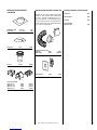
Figure 28
Figure 29
Step 9. Reassemble all removed components
by reversing the procedures outlined in the
preceding steps. Use pipe joint compound or
Teflon tape on all pipe fittings before installing
(ensure propane resistant compounds are used
in propane applications, do not use pipe joint
compounds on flare fittings).
Step 10. Attach the conversion label provided
in the conversion kit to the rating plate on the
appliance.
Step 11. Turn on gas supply and test for gas
leaks. (See
step 6
on page 8.)
Figure 27
Step 5. Millivolt Systems – Attach manom-
eter to the manifold side pressure test fitting
and verify manifold pressure reads 3.5 inches
water column (0.87 kPa) for natural gas, and
10.0 inches water column (2.49 kPa) for pro-
pane gas.
Step 6. See
Figure 26
and remove the pilot
hood assembly to access the hexed pilot ori-
fice. Remove and replace the orifice with the
one provided with the kit.
When reinstalling the ignitor assembly, use
extreme care to prevent damage and break-
age. Do not apply any leverage to the ignitor
assembly while restoring the retainer clip to
its original position.
All Models
Step 8. Unscrew the orifice from the manifold
and replace it with the one provided with the
kit
.
See the following table for orifice sizes for
natural and propane models.
Figure 29
illus-
trates the orifice.
Refer to
Figure 27
and replace the pilot orifice
as follows: Remove the pilot hood assemble
to access the hexed polot ofifice.
Remove the pilot orifice and replace it with the
one provided with the conversion kit. Reinstall
the pilot assembly by reversing the steps de-
tailed here.
Figure 26
Pilot
Orifice
Pilot
Orifice
LSBV
Series Natural Propane
Orifice Size
3628 #26 #45
4228 #26 #45
Electronic Appliances
Step 7. SIT Electronic Valves - See
Figure 28
and the instructions provided with the kit.
Remove the slotted cap screw, o-ring, pres-
sure-regulating adjusting screw and spring,
then discard.
Modify the pressure regulator from the kit.
Using a standard tin snip cutting tool, proceed
to trim shoulder off of the regulator.
Install new components and modified pres-
sure regulator from the kit.
Attach manometer to the manifold side pres-
sure test fitting and adjust screw until pres-
sure reads 3.5 inches water column (0.87 kPa)
for natural gas, and 10.0 inches water column
(2.49 kPa) for propane gas.
Modified Kit
Pressure Regulator
- After Trim
Remove
These
Components
SIT VALVE
Kit Pressure
Regulator - Before
Trim

16 NOTE: DIAGRAMS & ILLUSTRATIONS NOT TO SCALE.
Lennox Hearth Products reserves the right to make changes at any time, without notice, in design,
materials, specifications, prices and also to discontinue colors, styles and products.
Consult your local distributor for fireplace code information.
Printed in U.S.A. © 2007 by Lennox Hearth Products
P/N 850,042M REV. A 12/2008 1110 West Taft Avenue • Orange, CA 92865
-
 1
1
-
 2
2
-
 3
3
-
 4
4
-
 5
5
-
 6
6
-
 7
7
-
 8
8
-
 9
9
-
 10
10
-
 11
11
-
 12
12
-
 13
13
-
 14
14
-
 15
15
-
 16
16


Lennox Crestline LSBV-3628MP Manuel utilisateur
- Catégorie
- Cheminées
- Taper
- Manuel utilisateur
dans d''autres langues
Documents connexes
Autres documents
-
 Lennox Hearth FGCK Manuel utilisateur
-
Superior Fireplaces BRT40ST Mode d'emploi
-
 Lennox Hearth ADAGIO-EN Manuel utilisateur
-
Astria Fireplaces Altair Mode d'emploi
-
-
-
 Lennox Hearth Products MPB4540CNE Manuel utilisateur
-
-


