
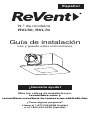
Installation Guide
Read and Save These Instructions
Watch the installation videos at:
reventfans.com and
reventfans.com/how-to-remove-an-old-bath-fan
Questions? Call
1-877-543-8698 (English) or
1-800-615-5439 (French)
model
RVL50, RVL70
Need Help?
English

1
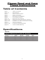
Table of Contents
Please Read and Save
These Instructions
page 1
page 1-2
page 3
page 4
page 5
page 6
page 7-9
page 10-16
page 16-21
page 21
page 21-22
page 23
Table of Contents
Specifications
What’s Inside The Box
Safety Information
Planning Your Installation
Connecting The Duct
Removing Your Old Fan
SheetLock® Easy Roomside Installation
Installation For New Construction Framing
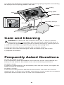
Care And Cleaning
Frequently Asked Questions
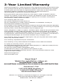
3-Year Limited Warranty
...............
............
...............
...............
...............
...............
............
........
........
.............
........
.............
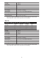
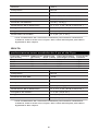
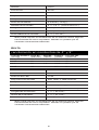
Specifications
RVL50
performance at 4" and 3" ducting
Duct
Size
4 in
4 in
3 in
3 in
Energy
(watts)
5.9
7.5
5.5
7.4
Static Pressure
(in wg)
0.1
0.25
0.1
0.25
Airow
(cfm)
50
41
50
42
Sound
(sones)
0.5
0.7
0.5
1.2

2
Voltage
Frequency
LED Watts
LED Brightness
LED Color Temp
Fan Weight
Shield Size
Housing Length*
Housing Width*
Housing Depth*
120 V
60 Hz
13 W
900, 1000, or 1000 Lumens
2700, 4000, or 5000 Kelvin
4.0 Lbs. ( 1.8 Kg )
9 3/4 x 9 3/4 in ( 24.8 x 24.8 cm )
7 1/4 in ( 18.4 cm )
7 1/2 in ( 19.1 cm )
4 3/8 in ( 11.1 cm )
*This may require modification of your current opening. Some hand
tools required. Power tools may also be necessary.
RVL70
Voltage
Frequency
LED Watts
LED Brightness
LED Color Temp
Fan Weight
Shield Size
Housing Length*
Housing Width*
Housing Depth*
120 V
60 Hz
13 W
900, 1000, or 1000 Lumens
2700, 4000, or 5000 Kelvin
4.0 Lbs. ( 1.8 Kg )
9 3/4 x 9 3/4 in ( 24.8 x 24.8 cm )
7 1/4 in ( 18.4 cm )
7 1/2 in ( 19.1 cm )
4 3/8 in ( 11.1 cm )
*This may require modification of your current opening. Some hand
tools required. Power tools may also be necessary.
performance at 4" and 3" ducting
Duct
Size
4 in
4 in
3 in
3 in
Energy
(watts)
7.9
11.1
10.9
9.7
Static Pressure
(in wg)
0.1
0.25
0.1
0.25
Airow
(cfm)
70
60
60
45
Sound
(sones)
0.9
1.3

3
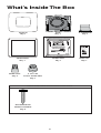
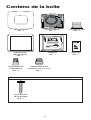
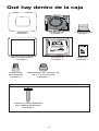
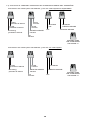
What’s Inside The Box
FAN
Qty:1
4” DAMPER
Qty:1
SHIELD
Qty:1
MANUAL
Qty:1
TEMPLATE
Qty:1
TRIM RING
Qty:1
4 TO 3 IN
DUCT ADAPTER
Qty:1
WIRE NUT
Qty:4
ROUNDHEAD
WOOD SCREW
Qty:4
USED FOR NEW CONSTRUCTION ONLY
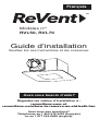
Installation Guide
Read and Save These Instructions
Watch the installation videos at:
reventfans.com and
reventfans.com/how-to-remove-an-old-bath-fan
Questions? Call
1-877-543-8698 (English) or
1-800-615-5439 (French)
model
RVL50, RVL70
Need Help?
English

4
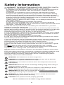
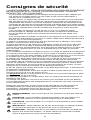
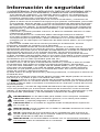
Safety Information
1.) WARNING - TO REDUCE THE RISK OF FIRE, ELECTRIC SHOCK,
OR INJURY TO PERSONS, OBSERVE THE FOLLOWING:
a) Installation work and electrical wiring must be done by qualified person(s) in
accordance with all applicable codes and standards, including fire-rated
construction.
b) Sufficient air is needed for proper combustion and exhausting of gases
through the flue (chimney) of fuel burning equipment to prevent back drafting.
Follow the heating equipment manufacturer's guideline and safety standards,
such as those published by the National Fire Protection Association (NFPA), the
American Society for Heating, Refrigeration and Air Conditioning Engineers
(ASHRAE), and the local code authorities.
c) When cutting or drilling into wall or ceiling, do not damage electrical wiring and
other hidden utilities.
d) Ducted fans must always be vented to the outdoors.
e) If this unit is to be installed over a tub or shower, it must be marked as
appropriate for the application and be connected to a GFCI (Ground Fault Circuit
Interrupter) - protected branch circuit.
2.) Use this unit only in the manner intended by the manufacturer. If you have
questions, contact the manufacturer.
3.) Before servicing or cleaning unit, switch power off at service panel and lock the
service disconnecting means to prevent power from being switched on accidentally.
When the service disconnecting means cannot be locked, securely fasten a
prominent warning device, such as a tag, to the service panel.
4.) This ventilation fan is approved for use over a bathtub or shower when installed
in a GFCI protected circuit. Do not use unapproved fans over a bathtub or shower
that are not approved for that application.
5.) Install ductwork in a straight line with minimal bends.
6.) Use 120 V, 60 Hz for the electrical supply and properly ground the unit. Follow
all local safety and electrical codes.
7.) Do not use this fan with any solid-state control device; such as a dimmer switch.
Solid-state controls may cause harmonic distortion, which can cause a motor
humming noise, as well as increase risk of fire or electric shock.
8.) To reduce the risk of fire or electric shock, do not block air entry shield.
9.) Mount with the lowest moving parts at least 8.2 ft (2.5 m) above floor or grade
level.
10.) Never place a switch where it can be reached from a tub or shower.
11.) Type IC for use in direct contact with thermal insulation not to exceed R-50.
12.) Not for use in cooking areas. (See PAGE 5 for details)
13.) This product must properly connect to the grounding conductor of the supply
circuit.
Follow the heating equipment manufacturer’s guideline and safety standards, such
as those published by the National Fire Protection Association (NFPA), the
American Society for Heating, Refrigeration and Air Conditioning Engineers
(ASHRAE), and the local code authorities.
WARNING: Not suitable for use as a range hood.
CAUTION: For General Ventilating Use Only - Do Not Use To Exhaust
Hazardous Or Explosive Materials And Vapors.
CAUTION: Do not install in locations where the temperature will exceed
104°F (40°C).
IMPORTANT: Exercise care to not damage existing wiring when cutting or
drilling into walls or ceilings.
NOTE: Make sure duct work size is a minimum of the discharge. Do not
reduce. Reducing the duct size can increase fan noise.
IMPORTANT: You may want to consult with a qualified licensed electrician
regarding the wiring of your ventilation fan.
WARNING: To reduce the risk of electric shock, please disconnect the
electrical supply circuit before servicing.
CAUTION: This product must be properly grounded.
Go to reventfans.com to obtain a copy of this manual.

5
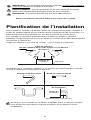
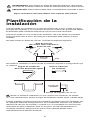
NOTE: If installing in existing construction, you may need to have access to
space above and below the installation location.
Cooking Area
do not install above or
inside this area
Cooking
Equipment Floor
Turning angle too sharp
Too many elbows
Avoid duct shrink
Elbow near the body
Fan
Body
Minimum 18 in ( 45.72 cm )
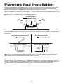
Planning Your Installation
When installing the ventilation fan in a new construction site, install the main body
of the FAN and duct work during the rough-in construction of the building. The
SHIELD should be installed after the finished ceiling is in place.
When installing in existing construction, use the provided cutout TEMPLATE for the
ceiling. SHIELD edge should overlap finished ceiling.
Not for use in cooking area - see diagram below.
Do not install ventilation fan in areas where the duct work will require configuration
as shown.
There are multiple installation configurations possible for this ventilation fan. Not all
configurations are shown. If your installation requires a variation other than those
shown, consult with a licensed contractor to determine the best installation for your
project. If you are replacing an existing fan, ensure that the new FAN will
adequately cover the existing opening.

6
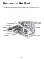
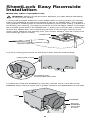
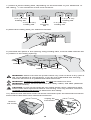
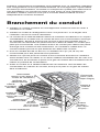
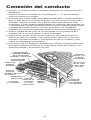
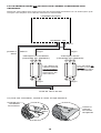
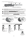
Connecting the Duct
● Install a circular duct to outlet and secure it with duct tape or clamps.
● Install the duct to the outlet with a gradient 1°~2° to the outside as shown.
● The ducting from this FAN to the outside of the building has a strong effect on
● the air flow, noise and energy use of the fan. Use the shortest, straightest duct
● routing possible for best performance, and avoid installing the FAN with smaller
● ducts than recommended. Insulation around the ducts can reduce energy loss
● and inhibit mold growth. Fans installed with existing ducts may not achieve their
● rated airflow.
● For models RVL50 or RVL70, 4 in (10.16 cm) round is recommended for
● best performance.
● Ensure duct joints and exterior penetrations are sealed with caulk or other
● similar material to create an air-tight path, to minimize building heat loss and
● gain, and to reduce the potential for condensation.
● Place/wrap insulation around duct and/or FAN in order to minimize possible
● condensation buildup within the duct, building heat loss and gain.
INSULATION*
(Place around and
over Fan Housing.)
Seal gaps
around
housing.
ROUND
DUCT*
POWER
CABLE*
Seal duct
joints with
tape.
FAN
HOUSING
ROUND
ELBOWS*
ROOF CAP*
(with built-in
damper)
Keep duct
runs short.
WALL CAP*
(with built-in
damper)
*Purchase
separately.
OR

7
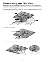
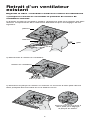
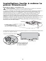
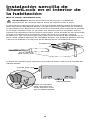
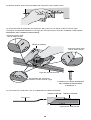
Removing An Old Fan
Watch the video: reventfans.com/how-to-remove-an-old-bath-fan
1.) Disconnect the electrical power supply and lock out the service
panel for the existing fan.
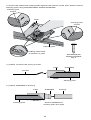
2.) Remove the grille from the existing fan. Pull the grille down to expose it’s two
springs. Squeeze each spring together and pull down again to release the springs
from the motor plate slots.
3.) Unplug the fan motor.
4.) Loosen the motor plate by inserting a flathead screwdriver into the slot in the
housing and twisting the screwdriver.
Pry loose with flat head
screwdriver if needed
springs
grille
ceiling
fan motor

8
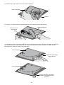
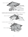
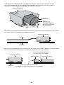
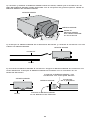
6.) Open or remove the electrical box and disconnect all wiring.
7.) Grab the fan housing with plyers and bend the fan housing inward to expose
the screws that mount the fan to the joist. Remove the screws or slide them
through the slots on the joist mounts.
5.) Remove the motor from the fan housing.
grab fan housing
with plyers
fan housing
motor
electrical box
disconnect
all wiring
fan housing
bend the fan housing
inward to expose the
screws
fan housing

9
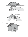
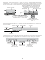
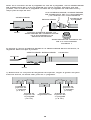
8.) Raise the housing into the ceiling. Pull the wiring out of the fan housing.
Remove the tape from the vent pipe and disconnect.
9.) Remove the fan housing from the ceiling.
expose and remove
the screws that mount
the fan to the joist
fan housing
fan housing
pull the wiring out
of the fan housing
ceiling
fan housing

10
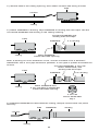
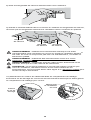
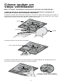
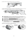
1.) Place the provided sheetrock cutout TEMPLATE on ceiling where you wish the
FAN to be (DAMPER and electrical positions shown on TEMPLATE). We suggest
using painter’s masking tape to hold the template in place while cutting. If there is a
pre-existing fan opening, use aligning windows to find it’s edges. Either cut through
the provided guide slots in the TEMPLATE, or mark your cut lines with a pencil and
remove the TEMPLATE. Use a sheetrock jab saw to cut your fan opening in the
ceiling. Note: Measure the opening from your old fan. ReVent® RVL50 or RVL70 fit
most openings without cutting.
SheetLock® Easy Roomside
Installation
Watch the video: reventfans.com
WARNING: Disconnect all AC Power Breakers or Fuses before attempting
to cut into your ceiling.
3.) Raise then slide the DAMPER up half way until the notch in the side of the
DAMPER aligns with the upper set of guides. Remove the DAMPER from the FAN.
Remove
DAMPER
from FAN
at notch
FAN
DAMPER
TEMPLATE
sheetrock jab saw
2.) Fold in ceiling joist mounts so that they’re flush with the FAN housing.
FAN
ceiling joist mount
fold ceiling joist
mounts flush with FAN

11
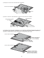
4.) Set the FAN in the ceiling opening, then attach conduit with wiring to FAN.
conduit
FAN
6.) Reattach DAMPER to FAN inside the ceiling, damper should click into place
securely.
ducting
conduit
DAMPER
FAN
5.) Attach DAMPER to ducting. Tape DAMPER to ducting with duct tape. Set the
connected DAMPER and ducting in the ceiling opening.
ceiling
4 in ducting
Connect DAMPER and
ducting with duct tape
Place DAMPER
inside CEILING opening
ceiling
ceiling
FAN
DAMPER
4 TO 3 IN
DUCT ADAPTER
Qty:1
Note: If ducting is 3 inch instead of 4 inch, use the included 4 TO 3 IN DUCT
ADAPTER. Use 4 inch pipe whenever possible. 4 inch pipe is quieter and better for
air flow.
ceiling
3 in ducting
Connect DAMPER, 4 TO 3 IN
DUCT ADAPTER, and
ducting with duct tape
Place DAMPER and
4 TO 3 IN DUCT ADAPTER
inside CEILING opening
FAN
DAMPER

12
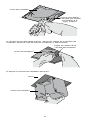
8.) Bend the holding tabs you selected outward.
9.) Set FAN into place in the opening using holding tabs, now the tabs hold the fan
in position in the ceiling opening.
holding tab
holding tab
holding tab
WARNING: Disconnect the AC power before any work is done to any part of
the circuit ReVent is connected to. If you do not understand this warning,
seek the services of a qualified licensed electrician.
WARNING: Copper to copper only. Do not use aluminum wire.
WARNING: Follow all local electrical and safety codes, and NEC (National
Electrical Codes).
CAUTION: If your house wires do not match these colors, determine what
each house wire represents before connecting. You may need to consult a
qualified licensed electrician to determine this safely.
10.) Remove the electrical cover set screw and slide open the electrical enclosure.
Disconnect FAN motor from electrical enclosure.
7.) Select a set of holding tabs, depending on the thickness of your sheetrock. In
the ceiling,
5
/
8
inch sheetrock is the most common.
5
/
8
in (1.6 cm)
holding tab
1
/
2
in (1.3 cm)
holding tab
final
securing
tab
5
/
8
in (1.6 cm)
holding tab
1
/
2
in (1.3 cm)
holding tab
remove
set screw
unplug fan
connectors slide

13
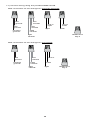
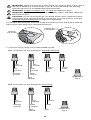
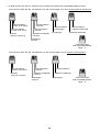
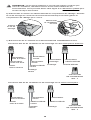
11.) Connect wiring using the provided WIRE NUTS.
line
ground
line
ground
housing
ground
line
neutral
line
neutral
FAN
neutral
light
neutral
line in
light
light
line in
FAN
FAN
Wire connection for fan and light on separate switches:
WIRE NUT
Qty:4
Wire connection for fan and light on one switch:
line
ground
housing
ground
line
neutral
FAN
neutral
light
neutral
line in
FAN
WIRE NUT
Qty:3
light

12.) Once connected, reattach the electrical enclosure.
14
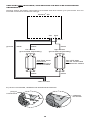
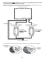
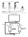
ReVent® fan
fan switch
(purchased separately) light switch
(purchased separately)
120V line AC
black
black
black
white
white
ground
lightfan
black
SWITCHES NOT INCLUDED, USE EXISTING OR MUST BE PURCHASED
SEPARATELY
Always follow all safety instructions included with the switch you purchase. Do not
exceed maximum electrical ratings.
The LED light
can be connected
to a dimmer switch
The FAN wires
cannot be
connected to a
dimmer switch
reattach
set screw
plug in
connectors
slide

15
14.) Align TRIM RING to vent position. Vent position is marked on TRIM RING
with the world “VENT”. Attach TRIM RING to FAN. TRIM RING attaches to FAN
body and presses into place when secure.
13.) Press and bend the final securing tabs flat against ceiling to lock the FAN in
place.
final securing tabs
sheetrock
(ceiling)
apply even
pressure to
each side of
securing tab
ceiling
TRIM RING
final securing tabs
FAN
electrical enclosure
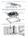
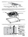
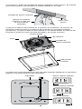
15.) Select desired LED color temperature by sliding the selector switch on the
back of the SHIELD.
daylight (5000K)
bright white (4000K)
warm white (2700K)
SHIELD

16
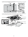
16.) Attach the SHIELD by squeezing the mounting springs together and inserting
the springs into the spring guides in the FAN.
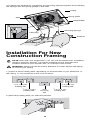
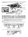
Installation For New
Construction Framing
NOTE: Even with new construction, you can use the SheetLock® installation
method; however, ReVent® can still be installed using a method home
builders would be more familiar with, as outlined in this section.
WARNING: Disconnect all AC Power Breakers or Fuses before attempting
to cut into your ceiling.
1.) Select a set of holding tabs, depending on the thickness of your sheetrock.
In
the ceiling,
5
/
8
inch sheetrock is the most common.
2.) Bend the holding tabs you selected outward.
5
/
8
in (1.6 cm)
holding tab
1
/
2
in (1.3 cm)
holding tab
final
securing
tab
5
/
8
in (1.6 cm)
holding tab
1
/
2
in (1.3 cm)
holding tab
SHIELD
mounting springs
TRIM RING
ceiling
FAN
spring guide
LED plug

17
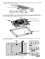
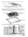
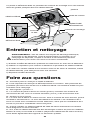
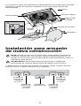
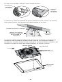
3.) Place the sheetrock holding tabs against the bottom of the joist. Attach FAN to
framing joist using ROUNDHEAD WOOD SCREWS.
ROUNDHEAD
WOOD SCREW
Qty:4
framing joist
mount
FAN
framing joist
framing joist
mount
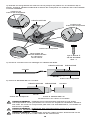
4.) Attach conduit with wiring to FAN.
conduit
DAMPERFAN
DAMPERFAN
5.) Attach DAMPER to ducting.
Attach DAMPER to
ducting with duct tape
framing joist
framing joist
ducting
holding tabs flush
to bottom of joist

18
WARNING: Disconnect the AC power before any work is done to any part of
the circuit ReVent is connected to. If you do not understand this warning,
seek the services of a qualified licensed electrician.
WARNING: Copper to copper only. Do not use aluminum wire.
WARNING: Follow all local electrical and safety codes, and NEC (National
Electrical Codes).
CAUTION: If your house wires do not match these colors, determine what
each house wire represents before connecting. You may need to consult a
qualified licensed electrician to determine this safely.
6.) Remove the electrical cover set screw and slide open the electrical enclosure.
Disconnect FAN motor from electrical enclosure.
7.) Connect wiring using the provided WIRE NUTS.
line
ground
line
ground
housing
ground
line
neutral
line
neutral
FAN
neutral
light
neutral
line in
light
light
line in
FAN
FAN
Wire connection for fan and light on separate switches:
WIRE NUT
Qty:4
Wire connection for fan and light on one switch:
line
ground
housing
ground
line
neutral
FAN
neutral
light
neutral
line in
FAN
WIRE NUT
Qty:3
light
remove
set screw
unplug fan
connectors slide

19
8.) Once connected, reattach the electrical enclosure.
ReVent® fan
fan switch
(purchased separately) light switch
(purchased separately)
120V line AC
black
black
black
white
white
ground
lightfan
black
SWITCHES NOT INCLUDED, USE EXISTING OR MUST BE PURCHASED
SEPARATELY
Always follow all safety instructions included with the switch you purchase. Do not
exceed maximum electrical ratings.
The LED light
can be connected
to a dimmer switch
The FAN wires
cannot be
connected to a
dimmer switch
reattach
set screw
plug in
connectors
slide
La page est en cours de chargement...
La page est en cours de chargement...
La page est en cours de chargement...
La page est en cours de chargement...
La page est en cours de chargement...
La page est en cours de chargement...
La page est en cours de chargement...
La page est en cours de chargement...
La page est en cours de chargement...
La page est en cours de chargement...
La page est en cours de chargement...
La page est en cours de chargement...
La page est en cours de chargement...
La page est en cours de chargement...
La page est en cours de chargement...
La page est en cours de chargement...
La page est en cours de chargement...
La page est en cours de chargement...
La page est en cours de chargement...
La page est en cours de chargement...
La page est en cours de chargement...
La page est en cours de chargement...
La page est en cours de chargement...
La page est en cours de chargement...
La page est en cours de chargement...
La page est en cours de chargement...
La page est en cours de chargement...
La page est en cours de chargement...
La page est en cours de chargement...
La page est en cours de chargement...
La page est en cours de chargement...
La page est en cours de chargement...
La page est en cours de chargement...
La page est en cours de chargement...
La page est en cours de chargement...
La page est en cours de chargement...
La page est en cours de chargement...
La page est en cours de chargement...
La page est en cours de chargement...
La page est en cours de chargement...
La page est en cours de chargement...
La page est en cours de chargement...
La page est en cours de chargement...
La page est en cours de chargement...
La page est en cours de chargement...
La page est en cours de chargement...
La page est en cours de chargement...
La page est en cours de chargement...
La page est en cours de chargement...
La page est en cours de chargement...
La page est en cours de chargement...
La page est en cours de chargement...
La page est en cours de chargement...
La page est en cours de chargement...
La page est en cours de chargement...
La page est en cours de chargement...
-
 1
1
-
 2
2
-
 3
3
-
 4
4
-
 5
5
-
 6
6
-
 7
7
-
 8
8
-
 9
9
-
 10
10
-
 11
11
-
 12
12
-
 13
13
-
 14
14
-
 15
15
-
 16
16
-
 17
17
-
 18
18
-
 19
19
-
 20
20
-
 21
21
-
 22
22
-
 23
23
-
 24
24
-
 25
25
-
 26
26
-
 27
27
-
 28
28
-
 29
29
-
 30
30
-
 31
31
-
 32
32
-
 33
33
-
 34
34
-
 35
35
-
 36
36
-
 37
37
-
 38
38
-
 39
39
-
 40
40
-
 41
41
-
 42
42
-
 43
43
-
 44
44
-
 45
45
-
 46
46
-
 47
47
-
 48
48
-
 49
49
-
 50
50
-
 51
51
-
 52
52
-
 53
53
-
 54
54
-
 55
55
-
 56
56
-
 57
57
-
 58
58
-
 59
59
-
 60
60
-
 61
61
-
 62
62
-
 63
63
-
 64
64
-
 65
65
-
 66
66
-
 67
67
-
 68
68
-
 69
69
-
 70
70
-
 71
71
-
 72
72
-
 73
73
-
 74
74
-
 75
75
-
 76
76


dans d''autres langues
- English: ReVent RVL50 Installation guide
- español: ReVent RVL50 Guía de instalación