
MODEL NUMBER:
PDI-179AV-B/C/G &
PDI-179AV5-B/C/G
Document Number:
PD196-396R4
Installation Guide
Page 1 of 6
PDi Communication Systems, Inc. ▪ 40 Greenwood Ln ▪ Springboro, Ohio 45066 USA ▪ www.pdiarm.com and www.mymedTV.com ▪ Phone 800.628.9870
SAFETY INFORMATION
Overhead Falling Hazard
Warning: To prevent injury, this apparatus must be securely
attached to the wall in accordance with the installation
instructions. Monitor can pose a striking a striking hazard
when mounted at an elevated position. Use only PDi
mounting brackets, support arms, and appropriate
hardware to assure monitor will not fall from the mounted
position.
Rain and Moisture
WARNING: To avoid the hazards of fire or electrical shock,
DO NOT expose this apparatus to rain or moisture.
Oxygen Environment
WARNING: Do not use in any oxygen tent or oxygen
chamber. Such use may cause a fire hazard.
Note to Cable TV Installer
This reminder is provided to call the cable TV systems installer’s
attention to Article 820-40 of the National Electrical Code. The code
provides guidelines for proper grounding and, in particular, specifies
that the cable ground shall be connected to the grounding system of
the building, as close to the point of the cable entry as practical.
Canadian installations shall be properly grounded in accordance with
the Canadian Electrical Code, Part 1.
Maintenance and Servicing
This unit does not require periodic maintenance other than cleaning.
Cleaning and Disinfection
Clean the exterior of this wall mount bracket by removing dust with a lint-
free cloth. Suggested cleaning agent is 5% Bleach and Water solution.
CAUTION: To avoid damage to the surface of the wall mount bracket, do
not use abrasive or chemical cleaning agents. Spot test a new disinfectant
by test cleaning a non-obvious small spot on the wall bracket surface.
Allow the disinfectant to soak per its instructions and then wipe clean. Do
not use the disinfectant if the wall bracket’s surfaces show any sign of
discoloration or softening.
Product Modification
Do not attempt to modify this product in any way without written
authorization. Unauthorized modification could void the user’s authority
to operate the product.
Copyright, Trademarks
© 2017 PDi Communication Systems, Inc. All rights reserved. Product
logos, brands and other trademarks displayed within PDi’s products are
the property of their respective trademark holders, who are not affiliated
with, endorsing or sponsoring PDi Communication Systems Inc. or our
products.

MODEL NUMBER:
PDI-179AV-B/C/G &
PDI-179AV5-B/C/G
Document Number:
PD196-396R4
Installation Guide
Page 2 of 6
PDi Communication Systems, Inc. ▪ 40 Greenwood Ln ▪ Springboro, Ohio 45066 USA ▪ www.pdiarm.com and www.mymedTV.com ▪ Phone 800.628.9870
IMPORTANT SAFETY INSTRUCTIONS
CAUTION: THIS INSTALLATION SHOULD BE MADE BY A QUALIFIED SERVICE PERSON
AND SHOULD CONFORM TO ALL LOCAL CODES. READ AND FOLLOW THE SAFETY
INSTRUCTIONS BEFORE ATTEMPTING THIS INSTALLATION.
1. Read these Instructions – All the safety and operating instructions should be read
before the product is operated.
2. Keep these Instructions – The safety and operating instructions should be retained
for future reference.
3. Heed all Warnings – All warnings on the product and in the operating instructions
should be adhered to.
4. Follow all Instructions – All warnings on the product and in the operating
instructions should be followed.
5. Do not use this apparatus near water – for example, near a bath tub, wash bowl,
in a wet basement; or near a swimming pool; and the like.
6. Clean only with dry cloth. Do not use liquid cleaners or aerosol cleaners.
7. Do not block any ventilation openings. Install in accordance with the
manufacturer’s instructions. The openings should never be blocked by placing the
product on a bed, sofa, rug, or other similar surface.
8. Do not install near any heat sources such as radiators, heat registers, stoves, or
other apparatus (including amplifiers) that produce heat.
9. DO NOT defeat the safety purpose of the polarized or grounding-type plug. This
product is equipped with a three-wire grounding-type plug, a plug having a third
(grounding) pin. This plug will only fit into a grounding-type power outlet. This is
a safety feature. If you are unable to insert the plug into the outlet, contact your
electrician to replace your obsolete outlet.
10. Protect the power cord from being walked on or pinched particularly at plugs,
convenience receptacles, and the point where they exit from the product.
11. Attachments – Only use attachments/accessories specified by the manufacturer.
12. Use only with cart, stand, tripod, bracket, or table specified
by the manufacturer, or sold with the apparatus. When a cart
is used, use caution when moving the cart/apparatus
combination to avoid injury from tip-over.
13. Unplug this apparatus during lightning storms when it is left
unused for long periods of time.
14. Refer all servicing to qualified service personnel. Servicing is required when the
apparatus has been damaged in any way, such as power-supply cord or plug is
damaged, liquid has been spilled or objects have fallen into the apparatus, the
apparatus has been exposed to rain or moisture, does not operate normally, or
has been dropped.
15. Power Sources – This product should be operated only from the type of power
source indicated on the marking label. If you are not sure of the type of power
supply to your home, consult your product dealer or local power company. For
products intended to operate from battery power, or other sources, refer to the
operating instructions.
16. Oxygen Environment – Do not use in an oxygen tent or oxygen chamber. Such use
may cause a fire hazard.
17. Lightning – For added protection for this product during a lightning storm, or
when it is left unattended and unused for long periods of time, unplug it from the
wall outlet and disconnect the antenna or cable system. This will prevent damage
to the product due to lightning and power-line surges.
18. Servicing – Do not attempt to service this product yourself as opening or removing
covers may expose you to dangerous voltage or other hazards. Refer all servicing
to qualified service personnel.
CONSIGNES DE SÉCURITÉ IMPORTANTES
CETTE INSTALLATION DOIT ÊTRE EFFECTUÉE PAR UN TECHNICIEN QUALIFIÉ ET
DOIT ÊTRE CONFORME À TOUS LES CODES LOCAUX. LIRE ET SUIVRE LES
CONSIGNES DE SÉCURITÉ AVANT DE PROCÉDER À L’INSTALLATION.
1. Lire ces instructions.
2. Conserver ces instructions.
3. Respecter tous les avertissements.
4. Suivez toutes les instructions - Tous les avertissements sur le produit et dans
les instructions d'utilisation doivent être suivis.
5. N'utilisez pas cet appareil près de l'eau - par exemple, près d'une baignoire,
d'un bol de lavage, dans un sous-sol humide; ou près d'une piscine; etc.
6. Nettoyez uniquement avec un chiffon sec. Ne pas utiliser de nettoyants liquides
ou aerosols.
7. Ne bloquez aucune ouverture de ventilation. Installez conformément aux
instructions du fabricant. Les ouvertures ne doivent jamais être bloquées en
plaçant le produit sur un lit, un canapé, un tapis ou une autre surface similaire.
8. Ne l'installez pas à proximité de sources de chaleur telles que radiateurs,
bouches de chaleur, poêles ou autres appareils (y compris les amplificateurs)
produisant de la chaleur.
9. NE PAS nuire à la sécurité de la fiche polarisée ou de la terre. Ce produit est
équipé d’une prise de terre à trois fils, une prise ayant une troisième broche
(mise à la terre). Cette fiche ne peut être insérée que dans une prise de courant
mise à la terre. Ceci est un élément de sécurité. Si vous ne parvenez pas à
insérer la fiche dans la prise, contactez votre électricien pour remplacer votre
prise obsolète.
10. Protégez le cordon d'alimentation afin qu'il ne soit pas piétiné ou pincé, en
particulier au niveau des fiches, des prises de courant et du point de sortie du
produit.
11. Pièces jointes - Utilisez uniquement les pièces jointes / accessoires spécifiés par
le fabricant.
12. Utilisez uniquement avec un chariot, un pied, un trépied, un support ou une
table spécifiés par le fabricant ou vendus avec l'appareil. Lorsqu'un chariot est
utilisé, faites attention lorsque vous déplacez la combinaison chariot / appareil
afin d'éviter toute blessure due au renversement.
13. Débranchez cet appareil en cas d'orage lorsqu'il n'est pas utilisé pendant une
longue période.
14. Confiez toute réparation à un personnel qualifié. Un entretien est nécessaire
lorsque l'appareil a été endommagé de quelque manière que ce soit, par
exemple si le cordon d'alimentation ou la fiche est endommagé, si du liquide a
été renversé ou si des objets sont tombés dans l'appareil, si l'appareil a été
exposé à la pluie ou à l'humidité, ne fonctionne pas normalement , ou a été
abandonné.
15. Sources d'alimentation - Ce produit doit uniquement être utilisé avec le type de
source d'alimentation indiqué sur l'étiquette. Si vous n'êtes pas sûr du type
d'alimentation de votre maison, consultez votre revendeur ou votre compagnie
d'électricité locale. Pour les produits conçus pour fonctionner à partir d'une
batterie ou d'autres sources, reportez-vous au mode d'emploi.
16. Environnement d’oxygène - Ne pas utiliser sous une tente à oxygène ou
chambre à oxygène. Une telle utilisation peut causer un risqué d'incendie.
17. Foudre - Pour renforcer la protection de ce produit pendant un orage ou
lorsqu'il est laissé sans surveillance et non utilisé pendant une période
prolongée, débranchez-le de la prise murale et de l'antenne ou du système de
câbles. Cela évitera d’endommager le produit en raison de la foudre et des
surtensions.
18. Entretien - N'essayez pas de réparer vous-même ce produit, car l'ouverture ou
le retrait des capots peut vous exposer à des tensions dangereuses ou à d'autres
dangers. Confiez toute réparation à un personnel qualifié.

MODEL NUMBER:
PDI-179AV-B/C/G &
PDI-179AV5-B/C/G
Document Number:
PD196-396R4
Installation Guide
Page 3 of 6
PDi Communication Systems, Inc. ▪ 40 Greenwood Ln ▪ Springboro, Ohio 45066 USA ▪ www.pdiarm.com and www.mymedTV.com ▪ Phone 800.628.9870
SCOPE:
To install a PDI-179AV or PDI-179AV5, with or without a backer plate. Contact PDi for complete list of compatible arm models that can
be used with this Wall Mount Bracket.
NOTES:
If you have questions, contact PDi ProServices at Ph: 1-800-628-9870, email: t1servic[email protected].
For more information on how to install PDi Backer Plates reference document PD196-094, included with the shipment of Backer Plates.
Disclaimer
The author and publisher have used their best efforts in preparing this manual. PDi Communication Systems, Inc. makes no representation
or warranties with respect to the accuracy or completeness of the contents of this manual and specifically disclaims any implied
warranties or merchantability or fitness for any particular purpose and shall in no event be liable for any loss of profit or any other
damages. The information contained herein is believed accurate, but is not warranted, and is subject to change without notice or
obligation.
MOUNTING GUIDELINES
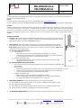
1. LOCATION – Make certain that the chosen Wall Mount Bracket location is near enough to the cable connection
interface so that it can be connected. The cables can also enter from behind the wall bracket. Position the Wall
Mount Bracket at a mounting height of 47±2 inches. See Figure 1.
2. WALL STRENGTH – These wall bracket mounting instructions cover the most desirable mounting method,
backing plate mounting, as well as other recommended mounting methods depending on wall construction.
IN ALL CASES the wall construction must be able to support a minimum compression loading of 350 PSI applied
perpendicular to the mounting locations.
a) Minimum installation Requirements
• Wall construction:
o Wall studs are to be wood, with a 2x4 minimum size and be spaced 16" on centers.
o Stud orientation shall be with the "4" inch dimension perpendicular to the surface plasterboard.
o The surface plasterboard shall have a maximum thickness of 5/8".
• Installation of PDi backer plate:
o Attaching fasteners will be 1/4" lag for the wood studs that provide a minimum of 2-1/2"
engagement with the wood studs.
b) PDi RECOMMENDED INSTALLATION METHOD
• At the time of this printing, the following configuration is the preferred method for installing PDi’s Wall
Mount Bracket.
• Wall construction:
o Wall studs are galvanized steel, 25 gauge minimum, with a 2x4 minimum size and be spaced 16" on centers.
o Stud orientation shall be with the "4" inch dimension perpendicular to the surface plasterboard.
o The surface plasterboard shall have a maximum thickness of 5/8".
• Installation of PDi backer plate:
o Attaching fasteners will be 1/4" diameter grade 5 (bolts or screws).
o Captive solid bar toggles: TOGGLER brand Snaptoggle, HILTI, or equivalent (see Appendix).
o Anchorage to two adjacent studs, two fasteners in each, is required.
3. HARDWARE REQUIRMENTS – Use the following hardware for all wall bracket installations.
a) All threaded rods, bolts, machine screws, and anchors will be ¼”-20UNC-2A thread, grade 5 or higher.
b) Backer plate recommendations below.
c) All threaded rods will be finished off with the washer and cap covers, supplied with the wall bracket.
d) Fastening anchors should be HILTI, Snaptoggle, or equivalent (see appendix).
4. THE MAXIMUM COMBINED WEIGHT of the monitor and support arm system must be no more than 55 pounds.
Figure 1

MODEL NUMBER:
PDI-179AV-B/C/G &
PDI-179AV5-B/C/G
Document Number:
PD196-396R4
Installation Guide
Page 4 of 6
PDi Communication Systems, Inc. ▪ 40 Greenwood Ln ▪ Springboro, Ohio 45066 USA ▪ www.pdiarm.com and www.mymedTV.com ▪ Phone 800.628.9870
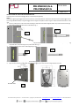
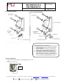
INSTALLATION WITH TOGGLE ANCHORS & BACKER PLATE
Fastening anchors should be Snaptoggle, HILTI, or equivalent (see appendix).
Notes:
Instructions regarding the toggle anchors are for reference, review manufacturer installation instructions for the specific toggle anchors.
If not using a PDi Backer Plate, arrange the toggle anchors using the hole pattern shown in Figure 7 below at the desired location on the
wall.
1. Drill a ½” (13mm) hole, in the center of the stud flange. Hold metal channel flat alongside plastic straps and slide channel through
hole. Minimum clearance behind wall 1-7/8” (48mm). Fig. 2
2. Hold ends of straps between thumb and forefinger and pull toward you until channel rests flush behind wall. Slide plastic cap along
straps with other hand until flange of cap is flush with wall. Fig. 3
3. Toggle should be through center of steel edge flange. Fig. 4
4. Cut or snap straps at wall by pushing side to side with flange of cap. Fig. 5
5. Align mounting holes on the PDi backer plate with the toggle anchors and install mounting hardware as shown.
Fig. 2
Fig. 5
Fig. 4
Fig. 6
PDi Backer Plate
Fig 7
Fig. 3

MODEL NUMBER:
PDI-179AV-B/C/G &
PDI-179AV5-B/C/G
Document Number:
PD196-396R4
Installation Guide
Page 5 of 6
PDi Communication Systems, Inc. ▪ 40 Greenwood Ln ▪ Springboro, Ohio 45066 USA ▪ www.pdiarm.com and www.mymedTV.com ▪ Phone 800.628.9870
PDI-179AV PARTS ASSEMBLY: PDI-179AV5 PARTS ASSEMBLY:
ELECTRICAL CONNECTIONS:
1. Attach coaxial cable from ARM to “F” fitting and wrench tighten to 15-20
in-lb.
2. Connect CAT connection(s)
PDI-179AV5 Cable Clamp Installation:
PDI-179AV5 allows for use of any combination of cables.
1. Install wall mount bracket to wall, before making
cable connections.
2. Connect cables from the PDi arm to appropriate
building cables. Wrench tighten coax connections.
3. Clamp cables using PD203-125 & PD185-013.
4. Insert cable connections and excess cable length
behind the wall mount bracket and attached the
cable clamp plates into bottom of wall bracket, and
secure with supplied PDIPPHMS83231SS screws.
Fig 8

MODEL NUMBER:
PDI-179AV-B/C/G &
PDI-179AV5-B/C/G
Document Number:
PD196-396R4
Installation Guide
Page 6 of 6
PDi Communication Systems, Inc. ▪ 40 Greenwood Ln ▪ Springboro, Ohio 45066 USA ▪ www.pdiarm.com and www.mymedTV.com ▪ Phone 800.628.9870
OTHER MOUNTING METHODS
There are other methods to mount a PDI-179AV or a PDI-179AV5, but the PREFERRED mounting is a backer plate system as described.
The mounting method used must meet the requirements as described on Page 3 of this document. The following mounting methods may
be used if the previously listed precautions are adhered to.
1. SOLID CONTRUCTION WALLS – Concrete, brick, and some types of cement block, cement expansion anchors can be used.
Proof tests the anchors to the manufacturer’s specifications in tension should be performed on the wall before installation
of the expansion anchors in the mounting location.
It is the responsibility of the architect and/or structural engineer, in charge of the project, to sign and submit the necessary
calculations that show the adequacy of the wall where the TV arm and mount will be installed. Drill four holes, which correspond to
the mounting hole pattern, to the manufacturer’s specifications of the chosen mounting fastener. Install four HILTI, or equivalent,
cement anchors per the manufacturer’s installation procedure. Position the wall bracket over the exposed mounting holes/studs.
Thread bolt and washer through bracket and into hole or nut and washers over studs. Tighten all bolts.
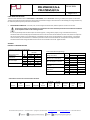
APPENDIX
KWIK BOLT 3 EXPANSION ANCHOR
Installation Information Strength Design
Setting Information
Units
Nominal anchor
diameter
1/4
3/8
Effective min
embedment
IN
1-1/2
2
(mm)
(38)
(51)
Min hole depth
IN
2
2-5/8
(mm)
(51)
(67)
Installation torque
Ft-lb
4
20
(Nm)
(5)
(27)
SNAPTOGGLE® HEAVY-DUTY HOLLOW-WALL ANCHORS
Anchor
UNC
thread
Drill dia.
½” Drywall
5/8”
Drywall
*½” w/ 25
gauge
stud
*5/8” w/
25 gauge
stud
Concrete
block
½” steel
plate
Stainless
in 3
BB
¼”-20
½”
265
356
425
464
1,080
1,288
1,735
Carbon Steel KB3 Strength Design
Design Information
Units
Nominal anchor diameter
1/4
3/8
Effective min. embedment
IN
1-1/2
2
(mm)
(38)
(51)
Min. hole depth in concrete
IN
2
2-5/8
(mm)
(51)
(67)
Pullout strength uncracked
concrete
Lb
1,575
NA
(kN)
(7.0)
Pullout strength concrete on
metal deck
Lb
1,750
2.245
(kN)
(7.8)
(10.0)
Installation torque
Ft-lb
4
20
(Nm)
(5)
(27)
-
 1
1
-
 2
2
-
 3
3
-
 4
4
-
 5
5
-
 6
6


