EUROSYSTEMS 05 Mode d'emploi
- Catégorie
- Mini motoculteurs
- Taper
- Mode d'emploi
Ce manuel convient également à

MOTOZAPPA
MOTOR-HOE
MOTOBINEUSE
MOTORHACKE
MOTOAZADA
MOTOENXADA
MOTORNI KULTIVATOR
GLEBOGRYZARKA SPALINOWA
IT Istruzioni d’uso
EN Operating Instructions
FR Mode d’emploi
DE Bedienungsanweisung
ES Instrucciones para la utilización
PT Instruções de uso
SL Navodila za uporabo
PL Instrukcja obsługi
Type: MZP05
MZP06


2
1
3
4

5
A
1
42
3
6
4a
1
1
A
A
13-15 mm 13-15 mm
6.1
6.2
6.3

87 1
2
3
4
5
6
7
8

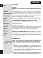
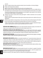
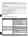
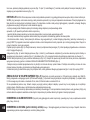
Leggere il manuale prima di usare la macchina -
Attenzione: rotazione fresa.
Read the instructions manual before operating on the
machine - Danger tiller rotation.
Lire le mode d’emploi avant l’usage - Attention: danger
rotation fraise.
Lesen Sie die Gebrauchsanweisung vor der Inbetriebnahme
- Achtung: frasenrotation.
Antes de proceder a montar la máquina lea atentamente
estas instrucciones - Atencion: la fresa gira.
Ler o manual das instruções antes do uso - Atenção:
rotação da fresa.
Pred uporabo naprave preberite navodila za uporabo –
Nevarno, vrtenje rezila.
Przed rozpoczęciem pracy z maszyną należy przeczytać
instrukcję obsługi - Niebezpieczeństwo wirujące noże
9
11
10
solo per
only for
seulement pour
nur für
sólo para
só para
Zgolj za
tylko dla
MZP06

Etichetta indicazione lo retromarcia
Label for reverse wire
Plaquette pour l à marche arrière
Aufkleber für RG-Bowdenzug
Etiqueta indicación hilo marcha-atrás
Etiqueta indicação de espia marcha-atrás
Nalepka za vzvratni kabel
Etykieta dla linki cofania
Etichetta acceleratore
Label accelerator
Plaquette acceleration
Aufkleber / Gashebel
Etiqueta acelerador
Plaqueta do acelerador
Nalepka pospeševalnika
Etykieta przyśpieszania
Retromarcia
Reverse drive
Marche arrière
Rückwärtsgang
Marcha atrás
Marcha atrás
Vzvratna prestava
Jazda do tyłu
Marcia avanti
Forward drive
Marche avant
Fahrantrieb vorwärts
Marcha adelante
Velocidade para frente
Prestava za vožnjo naprej
Jazda do przodu
Etichetta rotazione stegola
Sticker handlebar rotation
Plaquette rotation mancherons
Aufkleber Holmdrehung
Etiqueta rotacion de manilla
Plaqueta rotação do guiador
Nalepka o vrtenju krmilne ročice
Naklejka obrót kierownicy
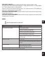
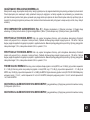
Manufacturer
Model: xxxx-xxxxxxxxxxx
Type: xxxxx xxxx | xxxxxxxxxxxx
Nr.: xxxxxxxxx-xxxxxx
Weight: xxx kg
Date: aaaa / E
Power: x.xx kW
1
2
3
4
5
6
7
8
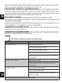
IT
1. Identicazione costruttore
2. Modello
3. Codice identicativo prodotto
4. Numero di serie articolo
5. Massa
6. Anno / Mese
7. Potenza motore
8. Tipologia prodotto
EN
1. Manufacturer identication
2. Model
3. Product identication code
4. Item serial number
5. Mass
6. Year / Month
7. Motor power
8. Type of product
FR
1. Identication du constructeur
2. Modèle
3. Code d’identication du produit
4. Numéro de série de l’article
5. Masse
6. Année / Mois
7. Puissance moteur
8. Typologie du produit
DE
1. Herstellerkennzeichnung
2. Modell
3. Produktkennziffer
4. Seriennummer des Artikels
5. Gewicht
6. Jahr / Monat
7. Motorleistung
8. Produktart
ES
1. Identicación fabricante
2. Modelo
3. Código de identicación producto
4. Número de serie artículo
5. Peso
6. Año / Mes
7. Potencia motor
8. Tipología producto
PT
1. Fabricante
2. Modelo
3. Código de identicação do produto
4. Numero de série
5. Massa
6. Ano de fabricação
7. Potência em kW
8. Tipo de produto
SL
1. Identikacija proizvajalca
2. Model
3. Identikacijska koda proizvoda
4. Serijska številka artikla
5. Teža
6. Leto / mesec
7. Moč motorja
8. Vrsta proizvoda
PL
1. Dane dotyczące producenta
2. Model
3. Kod identykacyjny produktu
4. Numer seryjny artykułu
5. Ciężar
6. Rok / miesiąc
7. Moc silnika
8. Rodzaj produktu

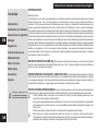
Indice
Introduzione
Condizioni di utilizzazione
Norme di sicurezza
Montaggio
Regolazione
Istruzioni d’uso
Manutenzione
Dati tecnici
Rumore aereo
Accessori
Guasti
Pericolo grave per l’incolumità
dell’operatore e delle persone
esposte.
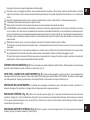
INTRODUZIONE
Gentile cliente,
la ringraziamo per la ducia accordata ai nostri prodotti e le auguriamo un piacevole utilizzo della sua
macchina.
Abbiamo creato queste istruzioni per l’uso allo scopo di assicurare, n dall’inizio, un funzionamento privo di
inconvenienti. Seguite attentamente questi consigli e avrete la soddisfazione di possedere per molto tempo una
macchina che funziona a dovere.Le nostre macchine, prima di essere fabbricate in serie, vengono collaudate in
maniera molto rigorosa e durante la fabbricazione vera e propria, sono sottoposte a severi controlli. Ciò costituisce,
per noi e per voi, la migliore garanzia che si tratti di un prodotto di riprovata qualità.
Questa macchina è stata sottoposta a rigorosi test neutrali nel paese d’origine e risponde alle norme
di sicurezza in vigore. Per garantire questo è necessario utilizzare esclusivamente ricambi originali.
L’utilizzatore perde ogni diritto di garanzia qualora vengano utilizzati ricambi non originali.
Con riserva di variazioni tecnico e costruttive. Per informazioni e ordinazioni di pezzi di ricambio, si prega citare
il numero di articolo e di produzione.
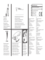
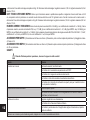
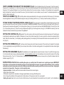
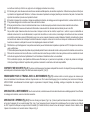
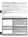
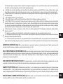
DATI PER L’IDENTIFICAZIONE (Fig.1) L’etichetta con i dati della macchina e il numero di matricola
è sul anco sinistro della motozappa sotto il motore. Nota Nelle eventuali richieste di Assistenza Tecnica o nelle
ordinazioni di parti di ricambio, citare sempre il numero di matricola della motozappa interessata.
CONDIZIONI DI UTILIZZAZIONE – LIMITI D’USO La motozappa è progettata e costruita per eseguire
operazioni di zappatura del terreno. La motozappa deve lavorare esclusivamente con attrezzi e ricambi originali.
Ogni utilizzo diverso da quello sopra descritto è illegale e ciò comporta l’annullo della garanzia oltre a un grave
pericolo per l’operatore e per le persone esposte.
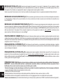
NORME DI SICUREZZA
Attenzione: prima del montaggio e la messa in funzione della macchina , leggere attentamente il libretto
istruzione. Le persone che non conoscono le norme di utilizzazione non possono usare la macchina.
1 L’uso della macchina è vietato ai minori di 16 anni e alle persone che hanno assunto alcol, medicine o
droghe.
2 La macchina è stata progettata per essere utilizzata da un solo operatore addestrato. L’utilizzatore
dell’apparecchio è responsabile di danni arrecati ad altre persone ed alle loro proprietà; controllare che altre
persone, sopratutto i bambini stiano lontani dalla zona di lavoro (10 mt.).
3 Togliere i corpi estranei dal terreno prima di iniziare le operazioni di zappatura Lavorare solo alla luce del
giorno oppure in presenza di una buona illuminazione articiale.
4 Non mettere in moto la macchina quando si è davanti alla fresa, né avvicinarsi ad essa quando è in moto.
Tirando la funicella di avviamento del motore, le frese e la macchina stessa devono rimanere ferme (se le
Istruzioni originali
IT
8

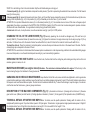
frese girano intervenire sul registro di regolazione del tendicinghia).
5 Durante il lavoro, per maggiore protezione, vanno indossate protezioni acustiche (cufe e/o tappi), calzature antinfortunistiche e pantaloni
lunghi. Fare attenzione, la fresa in movimento è potenzialmente pericolosa per mani e piedi. Importante inoltre camminare e non correre durante
il lavoro.
6 Durante il trasporto della macchina e tutte le operazioni di manutenzione, pulitura, cambio attrezzi, il motore deve essere spento.
7 Allontanarsi dalla macchina solo dopo avere spento il motore.
8 Non avviare la macchina in locali chiusi dove si possono accumulare esalazioni di monossido di carbonio.
9 AVVERTENZA La benzina è altamente inammabile, conservare il carburante in appositi recipienti. Non fare il pieno di benzina in locali chiusi
né con il motore in moto. Non fumare e fare attenzione alle fuoriuscite di combustibile dal serbatoio. In caso di fuoriuscita non tentare di avviare il
motore, ma allontanare la macchina dall’area interessata evitando di creare fonti di accensione nché non si sono dissipati i vapori della benzina.
Rimettere a posto correttamente i tappi del serbatoio e del contenitore della benzina. Non aprire il tappo della benzina con motore acceso o
quando è caldo.
10 Attenzione al tubo di scarico. Le parti vicine possono arrivare a 80° Sostituire i silenziatori usurati o difettosi.
11 Non lavorare sui pendii eccessivamente ripidi ed usare la massima precauzione nell’invertire il senso di marcia o nel tirare verso sé stessi
la macchina.
12 Prima di iniziare il lavoro con la macchina procedere ad un controllo visivo e vericare che tutti i sistemi antinfortunistici, di cui essa è dotata,
siano perfettamente funzionanti.E’ severamente vietato escluderli o manometterli. Sostituire i particolari danneggiati o usurati.
13 Ogni utilizzo improprio, riparazioni effettuate da personale non specializzato o l’impiego di ricambi non originali, comportano il decadimento
della garanzia e il declino di ogni responsabilità della ditta costruttrice.
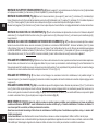
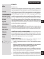
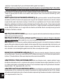
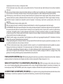
DISPOSITIVO DI SICUREZZA (Fig. 6) Tutte le motozappe sono dotate di dispositivo antinfortunistico. Detto dispositivo causa il disinnesto
automatico della trasmissione quando si rilasciano le relative leve (1) e (2).
NOTE PER IL LAVORO CON LA MOTOZAPPA (Fig. 6) A motore avviato appoggiare i coltelli sul terreno e, tenendo saldamente la
motozappa, inlare nel terreno lo sperone. Tirare la leva frizione (2) sulla stegola per iniziare a fresare. APPLICAZIONI : lavorazione di terreni leggeri
o di media pesantezza, fresatura, sminuzzamento, eliminazione infestanti, incorporamento di compost o fertilizzanti, ecc.
MONTAGGIO DELLA MOTOZAPPA La motozappa viene consegnata a destinazione, salvo accordi diversi, smontata e sistemata in un
adeguato imballaggio. Per completare il montaggio della motozappa osservare la seguente procedura.
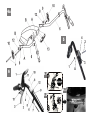
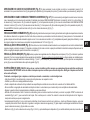
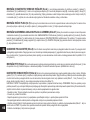
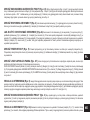
MONTAGGIO SPERONE (Fig. 2-3) Inlare il lato lungo dello sperone (Fig.2 part.1) nella parte terminale del braccio telaio e bloccarlo
ruotando la maniglia (2). Il ruotino di trasferimento (Fig.3 part.1) serve unicamente per il trasporto della motozappa. Si monta dopo aver ruotato di
180° lo sperone e bloccato allo stesso con la vite ad aletta (2). In fase di lavoro il ruotino va tolto: allentare la vite ad aletta quindi slare lo sperone
e riposizionarlo girato come in Fig.2.
MONTAGGIO SUPPORTO STEGOLA (Fig. 4) Montare il supporto (1) sulla motozappa tramite 4 viti (2) già posizionate sulla piastra,
rondelle (3) e dadi (4). Montare il passalo (5) come in gura.
IT
9

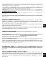
MONTAGGIO STEGOLA (Fig. 4a) Fissare i due tubi stegola (6) al supporto (1) con la vite (7), il distanziale (13), due rondelle (8) e il dado
(9) nei fori (A). Eseguire lo stesso procedimento per i fori (B) inserendo la vite (7), pomolo (10), distanziale (13), due rondelle spessore 4 mm.(12) e
l’altro pomolo (10) nell’ordine come rappresentato in gura. Le stegole possono essere regolate in altezza.
Svitare i due pomoli (10) ed inserire la vite (7) nel foro più adatto alle vostre esigenze di lavoro. La regolazione standard è l’altezza dei anchi.
MONTAGGIO CAVO ACCELERATORE (Fig. 5) Il lo acceleratore è già montato sia sul motore che all’interno del dispositivo acceleratore
(3). Tale dispositivo va ssato nel foro (A) del manubrio con la vite (2) e bloccato con il dado (1) avendo cura di controllare che il manettino (4) si
muova liberamente.
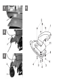
MONTAGGIO CAVO COMANDO TENDICINGHIA (Fig. 6-7) Il lo di comando è già collegato alla molla tendicinghia, ma occorre unirlo
alla leva di comando (2) installata sulla stegola. MARCIA AVANTI inserire il terminale (4) del lo (5) nel foro inferiore (3) della leva (2). Fare passare
il lo (5) completo del registro (7) nel foro passante del nasello (6). Nel caso di motozappa con RETROMARCIA inserire il terminale (10) nel foro (11)
della leva retromarcia(1). Fare passare il lo (8) completo di registro (9) nel foro passante del nasello (12). Solo per MZP06: il terminale (4) deve
essere inserito nel foro interno della leva (2), come nella Fig. 7.
REGISTRAZIONE DEI COMANDI (Fig. 6) Attenzione! La fresa deve iniziare a girare non prima di aver agito sui rispettivi comandi. Questo
si ottiene intervenendo sul registro dei li. Inoltre la leva che comanda la marcia di zappatura (2), deve avviare la fresa solo dopo aver compiuto metà
della propria corsa. Quando la leva retromarcia (1) è completamente tirata (posizione di lavoro), la molla di carico del tendicinghia retromarcia si deve
comprimere di circa 13-15 mm (Fig. 6.3).
REGOLAZIONE DELLO SPERONE (Fig. 2) Per ottenere una buona fresatura e un avanzamento corretto della motozappa, è possibile
regolare l’altezza dello sperone (1) allentando la maniglia (2) in modo da mantenere una posizione di lavoro orizzontale della macchina. A regolazione
avvenuta stringere la maniglia (2).
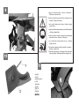
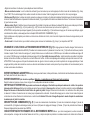
REGOLAZIONE DELLA STEGOLA (Fig. 4a) Le stegole possono essere regolate in altezza. Svitare i pomoli (10) e (11) ed inserire la vite
passante (7) nel foro più adatto alle vostre esigenze di lavoro. Solo per versione registrabile lateralmente: le stegole possono essere ruotate verso
destra o sinistra sollevando la leva della (Fig.11 part.1). Qualora il funzionamento della leva (Fig. 10 part.1) risultasse inefciente, svitare o avvitare
il dado (2) posto sotto il supporto stegola.
ISTRUZIONI D’USO ATTENZIONE prima di avviare il motore controllare sempre che la macchina sia in perfette condizioni di funzionamento.
IMPORTANTE : al primo utilizzo della macchina è assolutamente necessario vericare che all’interno del telaio sia presente l’olio di
lubricazione. Non avviare la macchina senza avere prima fatto questo controllo.
Terminato il montaggio accendere la motozappa e controllare che, portando l’acceleratore in posizione stop, il motore si spenga correttamente.
- Leggere attentamente il libretto istruzioni allegato del relativo motore.
- Controllare che il ltro aria sia ben pulito.
- Riempire il serbatoio di carburante del tipo indicato dalle speciche nel libretto del motore, usando un imbuto con il ltro.
- Non modicare la taratura del regolatore di velocità del motore e non far raggiungere ad esso una condizione di elevata velocità.
- Messa in moto del motore Aprire il rubinetto del carburante (per i motori provvisti) e posizionare su START la levetta dell’acceleratore (Fig.8 part.1)
IT
10

posta sulla stegola. Per la partenza con il motore a freddo consultare il libretto del motore. Afferrare la maniglia di avviamento e dare uno strappo
energico.
- Marcia avanti (Fig. 6) : A motore avviato appoggiare i coltelli sul terreno e, tenendo saldamente la motozappa, inlare nel terreno lo sperone. Impugnare
le stegole e premere il fermo di sicurezza (13) che impedisce l’innesto accidentale delle frese. Tirare la leva avanzamento (2) per tutta la sua corsa.
- Marcia indietro (Fig. 6): rilasciare la leva avanzamento (g.6, part.2) e dopo aver sbloccato il dispositivo (A) nel senso indicato dalla freccia portandolo
dalla posizione (Fig. 6.1) alla posizione (Fig. 6.2), tirare verso di sé l’altra leva posta sulla stegola (1).
ATTENZIONE: è importante che quando il dispositivo (A) è in posizione di blocco (Fig.6.1) la macchina non si muova. Se ciò non accade,
regolare/registrare opportunamente i cavi, come spiegato nel capitolo REGISTRAZIONE DEI COMANDI (Fig.6). Questa motozappa è progettata
per ridurre al minimo le emissioni di vibrazioni e rumore, tuttavia è buona norma intervallare lavori di lunga durata con piccole pause.
- Fine lavoro: terminato il lavoro, per arrestare il motore, portare la levetta dell’acceleratore (g. 5 part.2) nella posizione STOP.
SOSTITUZIONE OLIO NELLA TRASMISSIONE INFERIORE (Fig. 9) In linea di massima si dovrebbe sostituire l’olio ogni 100 ore
di lavoro (viscosità olio SAE 80 ).Procedere come segue: A) allentare il tappo a vite (1). B) collocare la macchina in posizione inclinata e aspirare
l’olio tramite una siringa. C) introdurre olio nuovo nella quantità di circa 0,2 litri per modello motozappa larghezza cm.40; quantità di crca 0,5 litri per
modello motozappa larghezza cm. 50. Per vericare il livello olio: Mettere la macchina in posizione orizzontale; svitare il tappo e controllare che
l’olio sia al livello inferiore del foro. Il tappo di riempimento e svuotamento corrisponde al livello olio.
IMPORTANTE! Per evitare l’inquinamento delle falde acquifere, l’olio esausto non deve essere gettato in scarichi fognari o canali idrici. Depositi
per l’olio esausto sono ubicati presso tutti i distributori di benzina, oppure in discariche autorizzate secondo le normative comunali del Comune di
residenza.
MANUTENZIONE FRESE A ZAPPETTE Pulire i mozzi delle frese, l’albero porta frese e la parte tagliente delle zappette dai residui di
terra, erba, li di ferro, corde ecc.
MANUTENZIONE MOTORE (vedere la pubblicazione specica) La motozappa viene consegnata con il motore a 4 tempi senza
olio. Riempire il serbatoio no al livello e con il tipo di olio indicato nel manuale del motore.
RIMESSAGGIO Mantenere serrati tutti i dadi, i bulloni e le viti per garantire il funzionamento della macchina nelle condizioni di sicurezza. Lasciar
raffreddare la macchina prima di immagazzinarla e comunque non riporla con benzina nel serbatoio all’interno di un edicio, dove i vapori possono
raggiungere una amma libera o una scintilla. Svuotare il serbatoio all’esterno. Per ridurre il pericolo di incendio mantenere il motore, il silenziatore e
la zona di immagazzinamento della benzina liberi da foglie, erba e grasso in eccesso.
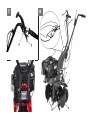
DESCRIZIONE COMPONENTI MACCHINA (Fig. 8) 1) Leva comando acceleratore. 2) Leva comando marcia di zappatura. 3) Leva
comando RM. 4) Maniglia per avviamento a strappo del motore. 5) Sperone per regolazione fresatura. 6) Frese. 7) Riparo frese. 8) Dischi proteggipiante
(solo per MZP06).
DATI TECNICI VERSIONE MZP05: Motore: per informazioni vedere la pubblicazione specica. Larghezza di lavoro delle frese è di 40
cm.,complete di carter di protezione. La velocità massima di rotazione della fresa è di 120 giri/minuto circa. Cambio: marcia avanti o marcia avanti
IT
11

+ retromarcia. Peso della motozappa completa è di Kg. 32. Dimensioni della motozappa: lunghezza massima 1,30 mt. larghezza massima 0,40 mt.
altezza 1,10 mt.
DATI TECNICI VERSIONE MZP06: Motore: per informazioni vedere la pubblicazione specica. Larghezza di lavoro delle frese è di 50
cm.,complete di carter di protezione. La velocità max.di rotazione della fresa è di 130 giri/minuto circa. Cambio: marcia avanti o marcia avanti +
retromarcia. Peso della motozappa completa è di Kg.44. Dimensioni della motozappa: lunghezza massima 1,30 mt. Larghezza massima 0,50 mt.
Altezza 1,10 mt.
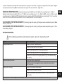
RUMORE AEREO E VIBRAZIONI Valore rilevato di potenza acustica LWA = 92 dB (A), con coefciente di incertezza K = ±1 dB (A). Valore
di pressione acustica, secondo normativa En709, Leq = 77,3 dB (A) con coefciente di incertezza K = ±1,1 dB (A) per MZP05. Leq = 83 dB (A) per
MZP06, con coefciente di incertezza K = ±1,2 dB (A). Valore massimo rilevato delle vibrazioni alle stegole secondo EN 709 e ISO 5394 = 7,2 m/s2,
coefciente K = ±3,6 m/s2 per MZP05. 8,6 m/s2 con coefciente K = ±4,3 m/s2 per MZP06.
ACCESSORI PER MZP05 1) Rincalzatore ad ali sse con attacco. 2) Risanatore prato a molle completo di protezione. 3) Arieggiatore a lame.
4) Fresa cm.16
ACCESSORI PER MZP06 1) Rincalzatore ad ali sse con attacco .2) Risanatore prato a molle completo di protezione. 3) Allargamento fresa
cm.75 con protezione.
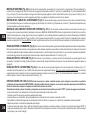
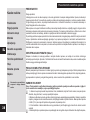
GUASTI
Prima di effettuare qualsiasi operazione, staccare il cappuccio della candela !
Guasto Rimedio
Il motore non si avvia Carburante esaurito, fare rifornimento.
Controllare che l’acceleratore sia posizionato su START.
Controllare che il cappuccio candela sia ben inserito.
Controllare lo stato della candela ed eventualmente sostituire.
Controllare che il rubinetto del carburante sia aperto (solo per i modelli di motore
in cui è previsto il rubinetto).
La potenza del motore diminuisce Filtro aria sporco, pulirlo.
Controllare che sassi o residui di terra e vegetazione non frenino la rotazione
delle frese, nel caso rimuoverli.
Le frese non ruotano Regolare i registri del cavo trasmissione.
Controllare che le frese siano ssate all’albero.
Controllare il posizionamento e l’integrità delle cinghie di trasmissione, riposizio-
narle e/o sostituirle.
Nel caso non si riesca a porre rimedio al guasto, rivolgersi ad un centro di assistenza autorizzato.
IT
12

List of contents
Introduction
Conditions of use
Safety measures
Assembly
Regulating
Instructions for operating
Maintenance
Technical Details
Noise
Accessories
Fault
Serious risk for operator and
bystander safety.
INTRODUCTION
Dear Customer:
Thank you for your trust in purchasing our products. We wish you to enjoy using our machines.
The following working instructions have been issued to ensure reliable operation from the beginning. If you
carefully follow such information the machine will operate with complete satisfaction have a long service life.
Our machines are tested under the most severe conditions before being put into production and are subject to
strict continuous tests during manufacturing stages. This unit has been tested in the country of origin by
independent testing authorities in accordance with strict work norms and safety standards.
When required, only original spare parts must be used to maintain guaranteed function and safety levels.
The operator forfeits any claims which may arise, if the machine shows to be tted with components other
than original spare parts. Subject to changes in design and construction without notice. For any questions or
further information and spare part orders,we need to be informed of the unit serial number printed on the side
of the machine.
IDENTIFICATION DATA (Fig. 1) The tag plate with the machine data and Serial N° is on the left side of
the cultivator under the engine. Note - Always state your motor cultivator serial number when you need Technical
Service or Spare Parts.
CONDITIONS AND LIMITATIONS OF USE This motor-hoe is designed and built to hoe the land. The
motor-hoe must only be used with original equipment and spares. Any use other than those described above is
prohibited and will involve, in addition to cancellation of the warranty, serious risk for the operator and bystanders.
SAFETY PRECAUTIONS
Attention: Before assembly and putting into operation, please read the operating instruction carefully.
Persons not familiar with these instructions should not use the machine.
1 Persons who are not familiar with the operating manual, as well as children, adolescents under the age
of 16 and persons under the inuence of alcohol, drugs or medication must not operate the mower.
2 The unit was designed in order to be used by 1 trained operator only. The person using the mower is
responsible for any accidents involving other persons or their property. When operating the machine, the
user should ensure that no others, particularly children, are standing in the area (10 mt.).
3 Before starting to mill, remove any foreign bodies from the soil. Work only in daylight or in good articial
light.
4 Do not start the machine if standing in front of the rotary cutter, neither get near the machine when
working. If pulling the starter short rope, the rotary cutter and the machine have to standstill (if rotation is
experienced, take action on the belt stretcher control nut).
5 During operations you need to use ear protectors, sturdy footwear and long trousers should be worn.
Translation of original user instructions
EN
13

Be very careful, when working, the blade is potentially hazardous for hands and feet. Always walk and never run while operating the machine.
6 During the machine transport and all the maintenance, cleaning, equipment change operations, the engine must be switched off.
7 Before leaving the machine, please switch the engine off.
8 Do not switch the machine on in closed rooms/areas where you can have carbon monoxide exhalations.
9 WARNING !! The petrol/gasoline is highly inammable. Store fuel only in containers specically designed fort he storage of such materials.
Don’t ll the tank neither in closed areas, nor when engine is on, don’t smoke and be careful to the petrol/gasoline loss from the tank. In case
of leak, don’t try to switch the engine on but move the machine away from the area in order to avoid ignition source until the gasoline vapours
fade away. Re-place the tank caps and the gasoline box. Never open the cap of the fuel tank, or add fuel, while the engine is running or the
unit is hot.
10 Keep attention to the exhaust pipe. The parts near the pipe can reach 80°C.
Replace the defective and/or worn out silencers Burn hazards !!!.
11 Do not work on excessively steep slopes and take every precaution when changing direction or pulling the machine towards you.
12 Before putting the machine into operations, check it visually and make sure all the accident prevention measures are working. It is absolutely
forbidden to exclude and/or to tamper with them. Replace worn or damaged elements.
13 In case the machine is incorrectly used, and/or the repairs are performed by non-authorized technical staff, and/or tted by spare parts
other then original ones: any use other than that described above is prohibited and will involve the cancellation of the warranty and the refuse
all responsability from the manufacturer.
SAFETY DEVICE (Fig. 6) All the motor-hoes feature accident-prevention devices. Such devices cause automatic disconnection of the drive
when the relevant levers are released (1) and (2).
NOTES FOR WORKING WITH THE MOTOR-HOE (Fig. 6) With the motor running, rest the blades on the ground and, holding the
motor hoe rmly, push the spur into the ground. Pull the clutch lever (2) on the handlebar to begin hoeing. APPLICATIONS: working light or medium-
heavy ground, hoeing, breaking up, weeding, digging in composts or fertilisers, etc.
HOW TO ASSEMBLE YOUR MOTOR-HOE Unless otherwise agreed, the motor cultivator is delivered disassembled and placed in a
packing case. For assembly to be completed, the step/by/step procedure is as follows.
FITTING THE DREWBAR (Fig. 2-3) Fit the long side of the drewbar (Fig. 2 part 1) into the end part of the frame arm and lock in place
by turning the handle (2). The purpose of the transfer wheel (Fig. 3 part 1) is for transporting the motor hoe only. This can be tted after turning the
drewbar by 180° and locking it in place with the wing screw (2). During motor hoe operation, the wheel should be removed: loosen the wing screw,
take off the drewbar and reposition it turned round as in Fig. 2
FITTING THE HANDLEBAR SUPPORT (Fig. 4) Fit the support (1) on the motor hoe using 4 screws (2) already positioned on the plate,
washers (3) and nuts (4). Fit the cable guide (5) as shown in the illustration.
EN
14

HOW TO ASSEMBLY AND ADJUST THE HANLEBARS (Fig.4a) Fix the 2 handlebar tubes (6) to the support (1) with the screw (7),
the spacer (13), 2 washers (8) 1 nut (9) into the holes (A). Perform the same proceeding with the holes (B) inserting the screw (7), the handle (10),
the spacer (13), 2 washers thickness 4 mm.(12) and the other handle (10) in the order as shown in the picture. The handlebars can be adjusted in
height. Unscrew the 2 handles (10) and insert the screw (7) into the hole which is most suitable to your job needs. The standard adjustment is on
operator’s body’s sides height.
THROTTLE ASSEMBLY (Fig. 5) The throttle cable is already assembled both on the engine and inside the throttle device (3). Such device
should be tightened to hole (A) of the handlebar using the screw (2) and locking it with the nut (1). Carefully check the handle (4) to freely turn.
FITTING THE BELT TIGHTENER CONTROL CABLE (Fig. 6-7) The control wire is already tted to the belt tightener spring, but this
must be connected to the control lever (2) tted on the handlebar. FORWARD MOVEMENT t the end (4) of wire (5) in the lower hole (3) of lever (2).
Pass the wire (5) complete with register (7) in the through hole of prong (6). In the case of motor hoes with REVERSE GEAR, t the end (10) in hole
(11) of the reverse gear lever (1). Pass the wire (8) complete with register (9) in the through hole of prong (12). FOR MZP06: terminal (4) has to be
inserted into the lever internal hole (2) as shown in the picture 7.
SETTING THE CONTROLS (Fig. 6) Important! The cutter must only start turning after the relevant controls have been set. This setting can
be performed by adjusting the wire register. Furthermore, the lever that controls hoeing start (2) must only start the cutter after completing half its
travel. When the reverse lever (1) is completely pulled (working position), the load spring of the reverse belt strecher must compress for about 13-15
mm (Fig. 6.3).
SETTING THE DREWBAR (Fig. 2) To achieve correct hoeing and correct forward movement of the motor hoe, the height of the drewbar
(1) can be adjusted by loosening the handle (2) so as to keep the machine in horizontal working position. Once adjustment has been made, tighten
the handle (2).
SETTING THE HANDLEBAR (Fig. 4a) The handlebars can be height-adjusted. Loosen the knobs (10) and (11) and t the through screw
(7) in the holes that best suit your working requirements. For side-adjustable version only: the handlebars can be turned to the right or left by lifting
the lever shown in (Fig. 11 part 1). If the lever device (1) seems not to be working , please unscrew or screw up the nut (2) which is placed under rhe
handlebar support (Fig. 10).
INSTRUCTIONS ATTENTION ! Before switching the engine on, carefully check if the motor-hoe is in perfect good repair. IMPORTANT:
at the rst use of the machine it is absolutely necessary to verify that inside the chassis to be present the lubrication oil. Do no start the
unit/machine on before having done such control. When you have nished the assembly, switch the motor hoe on and check , bringing the
accelerator to stop position , the engine to shut completely down.
- Engine instructions: Carefully read the istructions booklet anclosed to the relevant engine.
- Check if the air lter is clean.
- Fill the tank in as per the fuel described in the engine specications and using a lter lling funnel.
- Do not change the calibration of the speeds control rotation device of the engine in order not to over-speed it.
- Starting the motor Open the fuel cock (for motors that feature such cock) and position the accelerator lever (Fig. 8 part 1) on the handlebar on
EN
15

START. For cold starting, refer to the motor booklet. Grip the start handle and give a strong pull.
- Forward speed (g. 6) : grip the handlebars and press the safety device (13) which is preventing the accidental tines connection. Pull the forward
lever (2) all its way long.
- Reverse speed (g. 6): release the forward control lever (Fig.6, part 2) and after having unlocked the device (A) in the direction shown by the arrow
moving it from the position (Fig. 6.1) to the position (Fig. 6.2), pull towards you the other lever (1) on the handle.
ATTENTION: It is important that when the device (A) is in the locked position (Fig. 6.1) the machine does not move. If this does not happen, adjust
appropriately the cables, as explained in the SETTING THE CONTROLS chapter (Fig.6).This motor hoe has been designed to produce minimum
vibrations and noise. Nevertheless, it is a good idea to interrupt long jobs with short pauses.
- End of work: after work, to stop the motor, move the accelerator lever (g. 5 part 2) to STOP position.
CHANGING THE OIL IN THE LOWER DRIVE (Fig. 9) Generally speaking, the oil should be changed every 100 work hours (oil
viscosity SAE 80 ). Proceed as follows: A) loosen the screw cap (1). B) place the machine at an angle and suck up the oil using a syringe. C) ll up
with about 0.2 litres of new oil for the model of motor hoe with width 40 cm; about 0.5 litres for the model of motor hoe with width 50 cm.
To check the oil level: Place the machine in horizontal position; unscrew the cap and make sure the oil is at the lowest level of the hole. The ller
and emptying cap corresponds to the level of the oil.
ATTENTION! The used oil must not be drained into the sewer system or waterworks. In order to prevent any pollution to the water-table. Most garages
have used oil deposits, or use the authorized deposits according to your local authority regulations.
SERVICING FOR THE HOE TILLERS Clean the tiller hubs, the tiller-shaft and the cutting hoe parts making sure they are free from soil
residues, grass, iron wires, etc. etc.
MAINTENANCE ENGINE (see engine manual) Attention - The motor-hoe is delivered without oil in engine. Fill the tank up to the
level and using the type of oil indicated in the engine manual.
GARAGING AND SCHEDULED MAINTENANCE Keep attention that all the nuts, screws and bolts are tightened in order to guarantee
a good machine working on safety conditions. Leave the machine to cool before garaging anyhow don’t room it if the tank still contains some fuel as
the vapours could reach some blazes or sparks. The fuel tank is to be drained outdoors only. To lower the re danger , keep the engine , the silencer
and the fuel area free from leaves , grass or greasy substances.
DESCRIPTION OF THE MACHINE COMPONENTS (Fig. 8) 1) Accelerator control lever. 2) Hoeing start control lever. 3) Reverse
gear control lever. 4) Motor pull-start handle. 5) Cutting adjustment drewbar. 6) Cutters. 7) Cutter guard. 8) Plant protection discs (for MZP06 only).
TECHNICAL DETAILS OF MOTOR HOE MZP05 Motor: for details, see the specic publication. Working width of cutters is 40 cm,
complete with protection guard. Top cutter rotation speed is 120 rpm approx. Transmission : single speed or single speed+reverse speed. Weight of
the complete motor hoe is 32 kg. Motor hoe dimensions: max length 1.30 m max width 0.40 m height 1.10 m.
TECHNICAL DETAILS OF MOTOR HOE MZP06 Motor: for details, see the specic publication. Working width of cutters is 50 cm,
EN
16

complete with protection guard. Top cutter rotation speed is 130 rpm approx. Transmission : single speed or single speed+reverse speed. Weight of
the complete motor hoe is 44 kg. Motor hoe dimensions: max length 1.30 m max width 0.50 m height 1.10 m.
NOISE AND VIBRATION LEVEL Measured sound power level with En709, Lwa = 92 dB (A), with a uncertainty value K = ±1 dB (A).
Measured sound pressure level with En709, Leq = 77,3 dB (A), with a uncertainty value K = ±1,1 dB (A) for MZP05 and Leq = 83 dB (A), with a
uncertainty value K = ±1,2 dB (A) for MZP06. Handlebar vibration in compliance with EN 709 and ISO 5349. Level max detected = 7,2 m/s2, uncertainty
value K = ±3,6 m/s2 for MZP05; level max detected = 8,6 m/s2, uncertainty value K = ±4,3 m/s2 for MZP06.
ACCESSORIES FOR MOTOR-HOE MZP05 1) Fixed-wing ridger with coupling. 2) Spring lawn weeder complete with guard. 3) Blade
blower. 4) 16 cm cutter.
ACCESSORIES FOR MOTOR-HOE MZP06 1) Fixed-wing ridger with coupling. 2) Spring lawn weeder complete with guard. 3) 75 cm
cutter widening with guard.
TROUBLESHOOTING
Before performing any maintenance and clearing work operation , please take the spark-plug cap off.!
FAULT FAULT CLEARANCE
The engine does not start Check the fuel level, if necessary refuel.
Check the throttle to be on START position.
Check the spark-plug connector to be properly attacched.
Check the spark-plug condition and if necessary replace it.
Check the fuel valve to be in the opened position (only for the models showing
such feature).
The engine power goes down The air lter is dirty – please clean it.
Check if any stone or soil/vegetation residue is stopping the tines rotation, in
case clean them.
The tines are not rotating Adjust the transmission cables registers.
Check the tines to be fasten to the shaft.
Check the transmission belts position and condition : realign position and/or
replace them.
In case you are not able to remedy the defect/damage according to a.m. table, please contact an authorized service center only .
EN
17

Table des matières
Introduction
Conditions d’utilisation
Mesures de sécurité
Montage
Réglage
Mode d’emploi
Entretien
Données techniques
Niveau sonore
Accessoires
Problème
Danger grave pour l’intégrité
de l’opérateur et des
personnes exposées.
INTRODUCTION
Cher client,
nous vous remercions de la conance que vous nous témoignez et vous souhaitons beaucoup de satisfaction
dans son utilisation. An de garantir d’emblée un fonctionnement sans accrocs nous avons créé cette notice
d’utilisation. Si vous observez exactement les indications suivantes votre appareil fonctionnera toujours à votre
entière satisfaction pendant longtemps.
Nos appareils avant la fabrication en série, sont mis à I’essai dans les conditions les plus sévères et, pendant
la fabrication même, sont soumis constamment à des contrôles très stricts. De ce fait, nous sommes sûrs de la
qualité de nos produits et pouvons vous garantir une machine à toute épreuve.
Cet appareil a été testé et contrôlé par un laboratoire indépendant selon des normes de travail et de sécurité très
sévères. Pour conserver à cet appareil les qualités et performances prévues, n’utilisez que des pièces détachées
originales. La qualité du travail et votre sécurité en dépendent. L’utilisateur perd tous ses droits à la garantie
lorsqu’il modie l’appareil par l’adjonction de pièces détachées plus non originales. Dans le but d’améliorer nos
produits nous nous réservons le droit d’y apporter des modications. Pour toutes questions ou commandes
concernant les pièces détachées, prière d’indiquer le numéro de référence.
DONNÉES D’IDENTIFICATION (Fig. 1) L’étiquette avec les caractéristiques de la machine et le numéro
de matricule se trouve sur le côté gauche de la motobineuse, sous le moteur. Note - Fournir le numéro de série
de la motobineuse pour toute demande d’assistance technique ou commande de pièces.
CONDITIONS D’UTILISATION - LIMITES D’EMPLOI La motobineuse a été conçue et réalisée
pour biner le terrain. Elle ne peut travailler exclusivement qu’avec des outils et des pièces de rechange d’origine.
Toute utilisation différente de celle préconisée est illégale et entraîne l’annulation de la garantie, mais représente
aussi un danger grave pour l’opérateur et les personnes exposées.
MESURES DE SECURITE
Attention: lire attentivement le manuel d’instructions avant de procéder au montage et à la mise en marche.
La machine ne doit être utilisée que par des personnes en connaissant le mode d’emploi.
1 Les personnes ne connaissant pas le contenu de la notice d’utilisation, les enfants, les adolescents de
moins de 16 ans ainsi que les personnes sous l’inuence de l’alcool, de drogues ou de médicaments ne
doivent en aucun cas utiliser l’appareil.
2 La machine a été conçue pour être utilisée par 1 seul opérateur compétent. L’utilisateur de l’appareil
répond entièrement des dommages causés à des tiers ou à leurs biens. Veiller à ce qu’aucun enfant ne
se trouve à proximité (10 mt.) .
3 Débarrasser le terrain au maximum de ses déchets avant de commencer les opérations de binage.
4 Ne pas mettre en marche la machine lorsqu’on se trouve devant la fraise et ne pas s’y approcher
lorsqu’elle est en marche. Lorsqu’on tire sur la corde du lanceur, les fraises et la machine ne doivent pas
Traduction du mode d’emploi original
FR
18

se mettre en marche (si c’était le cas, agir sur la vis de réglage du tendeur de courroie).
5 Porter des gants, des chaussures de sécurité avec semelles antidérapantes, des lunettes de protection. Utilisez des coquilles anti-bruit pour
la protection de l’appareil auditif. Attention : la fraise en mouvement représente un danger potentiel pour les mains et les pieds. Il est aussi très
important de marcher et pas de courir pendant le travail.
6 Pendant le transport de la machine et toutes les opérations d’entretien, de nettoyage ou de changement d’outils, le moteur doit être à l’arrêt.
7 Ne jamais s’éloigner de la machine avant d’en avoir éteint le moteur.
8 Ne pas jamais mettre en route la machine dans des locaux clos dans lesquels pourraient s’accumuler des émanations de carbone.
9 MISE EN GARDE L’essence est hautement inammable. L’essence doit être stockée dans des bidons prévus à cet effet.
Ne pas faire le plein d’essence dans des locaux clos et lorsque le moteur est en marche; ne pas fumer ; veiller à ce que le combustible ne
déborde du réservoir. En cas de débordement, ne pas tenter de mettre en route le moteur, mais éloigner la machine de la zone concernée
en évitant de créer des sources d’inammation jusqu’à ce que les vapeurs d’essence se soient dissipées. Remettre correctement en place
les bouchons du réservoir et du récipient contenant l’essence. Lorsque le moteur est en marche ou lorsque la motobineuse est chauffée, le
bouchon du réservoir ne doit pas être ouvert et le remplissage du réservoir est interdit.
10 Attention au pot d’échappement. Les parties avoisinantes peuvent atteindre des températures proches de 80°C. Remplacer les silencieux
usés ou défectueux.
11
Ne travaillez pas sur des pentes trop raides et soyez prudents pendant l’inversion du sens de marche ou lorsque vous tirez la machine vers vous-même.
12 Avant de commencer le travail, effectuer un contrôle visuel de la machine pour vérier si tous les systèmes contre les accidents du travail
dont elle est équipée fonctionnent parfaitement. Il est formellement interdit de les ôter ou de les altérer.
13 Une utilisation impropre, des réparations défectueuses effectuées par un personnel non spécialisé, ou l’emploi de pièces de rechanges
n’étant pas d’origine entraînent l’expiration de la garantie et exonèrent le constructeur de toute responsabilité.
DISPOSITIF DE SECURITE (Fig. 6) Toutes les motobineuses sont équipées de dispositif de sécurité. Ce dispositif provoque le débrayage
automatique de la transmission lorsque l’on relâche les leviers respectifs (1) et (2).
REMARQUES POUR LE TRAVAIL AVEC LA MOTOBINEUSE (Fig. 6) Le moteur étant en marche, appuyer les couteaux par
terre, tenir solidement la motobineuse et enfoncer l’éperon dans le sol. Tirer le levier d’embrayage (2) sur le mancheron pour commencer le fraisage.
APPLICATIONS : ameublissement de terrains légers à moyennement compacts, fraisage, émiettage, sarclage, incorporation de compost ou de
fertilisants, etc.
MONTAGE DE LA MOTOBINEUSE Sauf accord contraire, la motobineuse est livrée démontée dans son emballage spécial. Pour effectuer
le montage de la machine, suivre les instruction suivantes.
MONTAGE DE L’EPERON (Fig. 2-3) Placer le côté long de l’éperon (Fig. 2 rep. 1) dans la partie terminale du bras du châssis et le bloquer
en tournant la poignée (2). La roue de transport (Fig. 3 rep. 1) sert uniquement pour le transport de la motobineuse. Pour le monter, tourner d’abord
de 180° l’éperon et le bloquer au moyen de l’écrou à ailette (2). Pendant de travail, enlever la roue de transport : desserrer l’écrou à ailette, retirer
l’éperon et le remonter en le tournant comme l’indique la Fig. 2.
FR
19

MONTAGE DU SUPPORT DE MANCHERON (Fig. 4) Monter le support (1) sur la motobineuse en le xant par les 4 vis (2) déjà montées
sur la plaque, les rondelles (3) et les écrous (4). Monter le passe-l (5) comme l’indique la gure.
MONTAGE DU MANCHERON (Fig. 4a) Fixer les 2 tubes du mancheron (6) au support (1) avec la vis (7), l’entretoise (13), 2 rondelles (8) et
l’écrou (9) dans les trous (A). Suivre la même procédure pour les trous (B) introduisant la vis (7), poignée (10), entretoise (13), 2 rondelles d’épaisseur
4 mm (12) et l’autre poignée (10) dans l’ordre comme indiqué dans la gure. Les mancherons peuvent être réglés en hauteur.
Dévisser les 2 poignées (10) et introduire la vis (7) dans le trous le plus indiqué au travail à effectuer. Le réglage standard est la hauteur des hanches.
MONTAGE DU CABLE DE L’ACCELERATEUR (Fig. 5) Le l de l’accélérateur est déjà monté sur le moteur et à l’intérieur du dispositif
accélérateur (3). Ce dispositif doit être xé dans le trou (A) du guidon avec la vis (2) et bloqué par l’écrou (1), et s’assurer que la manette de gaz (4)
bouge librement.
MONTAGE DU CABLE DE COMMANDE DU TENDEUR DE COURROIE (Fig. 6-7) Le câble de commande déjà xé au ressort
tendeur de courroie doit être relié au levier de commande (2) installé sur le mancheron. MARCHE AVANT : introduire l’extrémité (4) du l (5) dans
l’orice inférieur (3) du levier (2). Faire passer le l (5) avec vis de réglage (7) par l’orice débouchant du nez (6). Dans le cas de motobineuse équipée
de MARCHE ARRIERE, introduire l’extrémité (10) dans l’orice (11) du levier de marche arrière (1). Faire passer le l (8) avec vis de réglage (9) par
l’orice débouchant du nez (12). Pour le MZP06 : introduire l’extrémitè (4) dans l’orice intérieur du levier(2) comme dans la photo 7.
REGLAGE DES COMMANDES (Fig. 6) Attention ! La fraise ne doit commencer à tourner qu’après avoir actionné les commandes respectives.
Cela est obtenu en intervenant sur la vis de réglage des câbles. De plus, le levier qui commande la marche de binage (2) ne doit faire démarrer la
fraise qu’après avoir fait la moitié de sa course. Lorsque le levier de marche arrière (1) est complètement tiré (position de travail), le ressort de charge
du tendeur de courroie de marche arrière doit se comprimer d’environ 13-15 mm (Fig. 6.3).
REGLAGE DE l’EPERON (Fig. 2) Pour obtenir un bon fraisage et un avancement correct de la motobineuse, il est possible de régler la
hauteur de l’éperon (1) en desserrant la poignée (2) de manière à maintenir une position de travail horizontale de la machine. Après le réglage, serrer
la poignée (2).
REGLAGE DU MANCHERON (Fig. 4a) Les mancherons peuvent être réglés en hauteur. Dévisser les pommeaux (10) et (11) et introduire
la vis (7) dans l’orice le plus indiqué au travail à effectuer. Seulement pour version à réglage latéral: les mancherons peuvent être tournés vers la
droite ou vers la gauche en soulevant le levier de la (Fig. 11 rep.1). Se le fonctionnement du levier (1) vous semble inefcasse, vous pouvez le régler
en vissant ou dévissant l’écrou (2) qui est plaçé sous le support du mancheron (Fig.10).
MODE D’EMPLOI ATTENTION. Avant de mettre le moteur en marche, toujours contrôler que le motobineuse se trouve en parfaites
conditions d’utilisation. IMPORTANT : avant l’utilisation de la machine vériée qu’il y a l’huile de lubrication à l’intérieur du châssis. Si
vous n’avez pas fait ce contrôle, ne faites pas démarrer la machine.
Quand vous avez terminé le montage il faut allumer la motobineuse et vérier qu’avec l’accélérateur en position « stop », le moteur doit
s’arrêter correctement.
- Instructions Moteur: Lisez attentivement le manuel d’instructions en annexe au moteur correspondant. Vériez si le ltre à air est propre.
-
Remplissez le réservoir avec un carburant étant du type indiqué par les spécications rapportées dans le livret du moteur, en utilisant un entonnoir à ltre.
- Ne modiez pas l’étalonnage du régulateur de vitesse de rotation du moteur et ne mettez pas ce dernier en condition de survitesse.
FR
20
La page est en cours de chargement...
La page est en cours de chargement...
La page est en cours de chargement...
La page est en cours de chargement...
La page est en cours de chargement...
La page est en cours de chargement...
La page est en cours de chargement...
La page est en cours de chargement...
La page est en cours de chargement...
La page est en cours de chargement...
La page est en cours de chargement...
La page est en cours de chargement...
La page est en cours de chargement...
La page est en cours de chargement...
La page est en cours de chargement...
La page est en cours de chargement...
La page est en cours de chargement...
La page est en cours de chargement...
La page est en cours de chargement...
La page est en cours de chargement...
La page est en cours de chargement...
La page est en cours de chargement...
La page est en cours de chargement...
La page est en cours de chargement...
La page est en cours de chargement...
La page est en cours de chargement...
La page est en cours de chargement...
La page est en cours de chargement...
La page est en cours de chargement...
La page est en cours de chargement...
La page est en cours de chargement...
La page est en cours de chargement...
-
 1
1
-
 2
2
-
 3
3
-
 4
4
-
 5
5
-
 6
6
-
 7
7
-
 8
8
-
 9
9
-
 10
10
-
 11
11
-
 12
12
-
 13
13
-
 14
14
-
 15
15
-
 16
16
-
 17
17
-
 18
18
-
 19
19
-
 20
20
-
 21
21
-
 22
22
-
 23
23
-
 24
24
-
 25
25
-
 26
26
-
 27
27
-
 28
28
-
 29
29
-
 30
30
-
 31
31
-
 32
32
-
 33
33
-
 34
34
-
 35
35
-
 36
36
-
 37
37
-
 38
38
-
 39
39
-
 40
40
-
 41
41
-
 42
42
-
 43
43
-
 44
44
-
 45
45
-
 46
46
-
 47
47
-
 48
48
-
 49
49
-
 50
50
-
 51
51
-
 52
52


EUROSYSTEMS 05 Mode d'emploi
- Catégorie
- Mini motoculteurs
- Taper
- Mode d'emploi
- Ce manuel convient également à
dans d''autres langues
- italiano: EUROSYSTEMS 05 Istruzioni per l'uso
- español: EUROSYSTEMS 05 Instrucciones de operación
- português: EUROSYSTEMS 05 Instruções de operação
- polski: EUROSYSTEMS 05 Instrukcja obsługi