Simplicity 040362-00 Manuel utilisateur
- Catégorie
- Groupes électrogènes
- Taper
- Manuel utilisateur

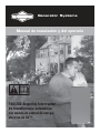
Generator Systems
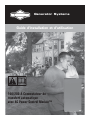
100/200 Amp Automatic
Transfer Switch
with ACPower Control Module™
Installation & Operator’s Manual
NOT
FOR
REPRODUCTION

2 BRIGGSandSTRATTON.COM
Copyright © 2012. Briggs & Stratton Power Products Group, LLC
Milwaukee, WI, USA. All rights reserved.
Briggs & Stratton Power Products is a registered
trademark of Briggs & Stratton Corporation
Milwaukee, WI, USA
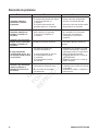
Thank you for your purchase of this Briggs & Stratton® Power Products automatic transfer switch. This product is designed
for use with specific home standby generators and may not function with generators produced by other manufacturers. Seek
a qualified electrical professional to determine applicability of this equipment to generators manufactured by others. When
operated and maintained according to the instructions in this manual, your power management system will provide many
years of dependable service.
This manual contains safety information to make you aware of the hazards and risks associated with this system and how to
avoid them. We have made every effort to provide for a safe, streamlined and cost-effective installation. As each installation
is unique, it is impossible to know of and advise of all conceivable procedures and methods by which installation might be
achieved. We do not know all possible hazards and/or the results of each possible method or procedure. It is important that
you read and understand these instructions thoroughly before attempting to install or operate this equipment. Save these
instructions for future reference.
This transfer switch requires professional installation before use. Refer to the Installation section of this manual for
instructions on installation procedures. Only licensed electrical contractors should install transfer switches. Installations must
strictly comply with all applicable federal, state and local codes, standards and regulations. Your installer should follow the
instructions completely.
Where to Find Us
You never have to look far to find Briggs & Stratton support and service for your system. Consult your Yellow Pages.
There are many authorized service dealers who provide quality service. You can also contact Technical Service by phone at
800-743-4115 between 8:00 AM and 5:00 PM CT, or on the Internet at BRIGGSandSTRATTON.COM.
For Future Reference
Please fill out the information below and keep with your receipt to assist in unit identification for future purchase issues.
Model Number
Revision
Serial Number
Date Purchased
NOT
FOR
REPRODUCTION

3
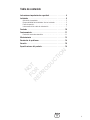
Table of Contents
Important Safety Instructions........................4
Installation ....................................5
Owner Orientation ............................................5
Installing Dealer/Contractor Responsibilities ........................5
Mounting Guidelines ..........................................6
Power Wiring Interconnections ..................................7
Controls ..................................... 10
Operation .................................... 11
Testing the Automatic Transfer Switch ...........................11
Maintenance .................................. 12
Troubleshooting................................ 14
Schematic Diagram ..........................................15
Wiring Diagram .............................................16
Warranty..................................... 17
Product Specifications ........................... 18
NOT
FOR
REPRODUCTION

4 BRIGGSandSTRATTON.COM
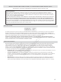
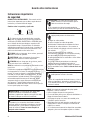
Important Safety Instructions
SAVE THESE INSTRUCTIONS - This manual contains
important instructions that should be followed during
installation and maintenance of the equipment.
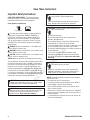
Safety Symbols and Meanings
The safety alert symbol indicates a potential personal
injury hazard. A signal word (DANGER, WARNING, or
CAUTION) is used with the alert symbol to designate a
degree or level of hazard seriousness. A safety symbol
may be used to represent the type of hazard. The signal
word NOTICE is used to address practices not related to
personal injury.
DANGER indicates a hazard which, if not avoided, will
result in death or serious injury.
WARNING indicates a hazard which, if not avoided, could
result in death or serious injury.
CAUTION indicates a hazard which, if not avoided, could
result in minor or moderate injury.
NOTICE addresses practices not related to personal injury.
The manufacturer cannot possibly anticipate every possible
circumstance that might involve a hazard. The warnings in
this manual, and the tags and decals affixed to the unit are,
therefore, not all-inclusive. If you use a procedure, work
method or operating technique that the manufacturer does
not specifically recommend, you must satisfy yourself that
it is safe for you and others. You must also make sure that
the procedure, work method or operating technique that you
choose does not render the equipment unsafe.
Electrical Shock Read Manual
Save These Instructions
WARNING Only qualified electricians should attempt
installation of this equipment, which must strictly comply
with applicable codes, standards and regulations.
WARNING Certain components in this product and
related accessories contain chemicals known to the State
of California to cause cancer, birth defects, or other
reproductive harm. Wash hands after handling.
WARNING Low voltage wire cannot be installed in
same conduit as power voltage wiring.
• Failure to follow above warning could cause personal
injury, damage and/or malfunction of equipment.
WARNING Failure to properly ground equipment can
result in electrocution.
• Do not touch bare wires.
• Do not use equipment with worn, frayed, bare or
otherwise damaged wiring.
• Do not handle electrical cords while standing in water,
while barefoot, or while hands or feet are wet.
• If you must work around a unit while it is operating, stand
on an insulated dry surface to reduce shock hazard.
• Do not allow unqualified persons or children to operate or
service equipment.
• In case of an accident caused by electrical shock,
immediately shut down all sources of electrical power
and contact local authorities. Avoid direct contact with
the victim.
WARNING Equipment contains high voltage that can
cause personal injury or death.
• Despite the safe design of the system, operating this
equipment imprudently, neglecting its maintenance or
being careless can cause possible injury or death.
NOTICE Improper treatment of equipment can damage it
and shorten its life.
• Use equipment only for intended uses.
• If you have questions about intended use, ask dealer or
contact Briggs & Stratton Power Products.
• Do not expose equipment to excessive moisture, dust,
dirt, or corrosive vapors.
• Remain alert at all times while working on this equipment.
Never work on the equipment when you are physically or
mentally fatigued.
• If connected devices overheat, turn them off and turn off
their circuit breaker/fuse.
NOT
FOR
REPRODUCTION

5
Installation
We sincerely appreciate your patronage. For this reason,
we have made significant effort to provide for a safe,
streamlined and cost-effective installation. Because each
installation is unique, it is impossible to know of and advise
the trade of all conceivable procedures and methods by
which installation might be achieved. Neither could we know
of possible hazards and/or the results of each method or
procedure. For these reasons,
Only current licensed electrical should attempt system
installations. Installations must strictly comply with all
applicable codes, industry standards and regulations.
Your equipment is supplied with this combined “Installation
and Operator’s Manual”. This is an important document and
should be retained by the owner after the installation has
been completed.
Every effort has been made to make sure that the information
in this manual is both accurate and current. However, the
manufacturer reserves the right to change, alter or otherwise
improve the system at any time without prior notice.
Home Owner Responsibilities
To help you make informed choices and communicate
effectively with your installation contractor(s),
Read and understand Owner Orientation before contracting
or starting your equipment installation.
To arrange for proper installation, contact the store at which
you purchased your equipment, your dealer, or your utility
power provider.
The equipment warranty is VOID unless the system is
installed by licensed electrical professionals.
Owner Orientation
The illustrations provided are for typical circumstances and
are meant to familiarize you with the installation options
available with your system.
Local codes, appearance, and distances are the factors that
must be considered when negotiating with an installation
professional. As the distance from the existing electrical
service increases, compensation in wiring materials must
be allowed for. This is necessary to comply with local codes
and overcome electrical voltage drops.
These factors will have a direct effect on the overall price
of your equipment installation.
Your installer must check local codes AND obtain permits
before installing the system.
• Readandfollowtheinstructionsgiveninthismanual.
• Followaregularscheduleincaringforandusingyour
equipment, as specified in this manual.
Installing Dealer/Contractor Responsibilities
• Readandobservethesafetyrules.
• Readandfollowtheinstructionsgiveninthismanual.
• Theinstallermayneedtoprovideappropriaterated
contactors based on loads to be controlled.
• Checkfederal,stateandlocalcodesandauthority
having jurisdiction, for questions on installation.
• Ensuregeneratorisnotoverloadedwithselectedloads.
If you need more information about the transfer switch, call
800-743-4115, between 8:00 AM and 5:00 PM CT.
Equipment Description
The transfer switch is designed to transfer the selected loads
found in normal residential installations when used with the
supervisory contacts provided. The load is connected either
to utility power (normal) or home standby power (generator).
The transfer switch monitors utility and generator voltages
and will automatically connect to the appropriate source
ofpower.
These switches make it easy for a licensed electrician to
complete a home standby installation. Service conduit and
conductors can be wired directly from the watt-hour meter
to the transfer switch. A separate disconnect and associated
wiring is not required when installed per applicable federal,
state and local codes, standards and regulations.
Major components of the transfer switch are a 2 pole utility
disconnect circuit breaker, a 2 pole generator disconnect
circuit breaker, a 2 pole double throw transfer switch, control
circuit board, fused utility terminals and interconnecting
wiring. The control board also has two inputs for current
transformers that sense generator current. These
components are housed in a NEMA 3R enclosure that is
suitable for both indoor and outdoor installations.
The transfer switch is solenoid-operated from utility or
generator inputs and contain suitable mechanical and
electrical interlock switches to eliminate the possibility of
connecting the utility service to the generator output. It
has ratings capable of switching full utility power into the
residence. In addition, a manual override lever is provided
for the transfer function.
The control board has active circuits sensing utility and
generator voltages. It creates a signal for generator start-up,
switch transfer and retransfer when utility is restored. The
control board also contains red and green LED’s indicating
the power sources available and two relay operated contacts
that provide supervisory control of external loads.
NOT
FOR
REPRODUCTION

6 BRIGGSandSTRATTON.COM
Delivery Inspection
After opening the carton, carefully inspect the transfer
switch components for any damage that may have occurred
duringshipment.
If loss or damage is noted at time of delivery, have the
person(s) making delivery note all damage on the freight bill
and affix his signature under the consignor’s memo of loss
or damage. If loss or damage is noted after delivery, contact
the carrier for claim procedures. Missing or damaged parts
are not warranted.
Shipment contents
• Automatictransferswitch(1)
• Installationandoperator’smanual(1)
• Currenttransformers(2)
To be supplied by installer:
• Connectingwireandconduit
• Variousspecialtytools/equipment
Mounting Guidelines
The system circuitry is enclosed in a NEMA Type 3R
enclosure suitable for indoor/outdoor use. Guidelines for
mounting the enclosure include:
• Installenclosureonafirm,sturdysupportingstructure.
• Theenclosuremustbeinstalledwithminimum
NEMA3R hardware for conduit connections.
• Topreventswitchcontactdistortion,levelandplumb
the enclosure. This can be done by placing washers
between the enclosure and the mounting surface.
• NEVERinstalltheswitchwhereanycorrosive
substance might drip onto the enclosure.
• Protecttheswitchatalltimesagainstexcessive
moisture, dust, dirt, lint, construction grit and
corrosivevapors.
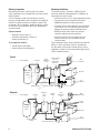
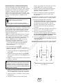
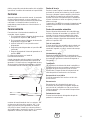
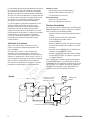
Typical automatic transfer switch installations are depicted
below. It is best if the transfer switch is mounted near
the utility meter, either inside or outside. Discuss layout
suggestions/ changes with the owner before beginning the
system installation process.
Main
Distribution
Panel
Transfer
Switch
Hot Water
Heater
Air
Conditioner
Contactor
Disconnect Switch
Generator
Watt -
Hourmeter
Branch
Circuits
Emergency Branch
Circuits
— — — — — — Control Wiring
Emergency
Load
Center
Alternate
Typical
Main
Distribution
Panel
Transfer Switch
w/ Service
and Generator
Disconnect
Hot Water
Heater
Air
Conditioner
Generator
Watt -
Hourmeter
— — — — — — Control Wiring
Disconnect Switch
Contactor
Branch Circuits
NOT
FOR
REPRODUCTION

7
Power Wiring Interconnections
All wiring must be the proper size, properly supported
and protected by conduit. All wiring should be done per
applicable federal, state and local codes, standards and
regulations. Obey wire type and torque specifications printed
on the terminal blocks and neutral/ground connector.
Approved for copper and aluminum conductors.
Complete the following connections between the transfer
switch, main distribution panel, utility power and generator.
Useinstaller-supplied300VACorgreaterwirethatcomplies
with Table 310.16 in the National Electric Code. Apply the
necessary correction factors and wire size calculations.
1. Set generator’s circuit breaker to OFF (open) position.
2. Set generator’s system switch to OFF position and
remove 15 Amp fuse from system control panel.
3. Turn off utility power to the standby generator and
transfer switch.
4. Connect utility service to transfer switch’s utility
disconnect circuit breaker terminals marked
“UTILITYCONNECTION”.
5. Connect utility service neutral to transfer switch
neutralterminal.
6. Connect main distribution panel feeder
conductors to transfer switch terminals marked
“LOADCONNECTION”.
7. Connect main distribution panel neutral conductor to
transfer switch neutral terminal.
8. Connect main distribution panel ground conductor to
transfer switch “GND” terminal.
Assure grounding electrode conductor is connected and
bonded per applicable federal, state and local codes,
standards and regulations.
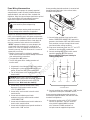
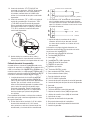
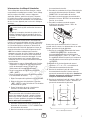
9. Connect feeder conductors from transfer switch
breaker “GENERATOR CONNECTION” terminals to
generator circuit breaker LINE1 and LINE2 terminals.
Each conductor must pass through hole of current
transformer before making connection.
10. Plug current transformer leads into “CT1” and “CT2”
terminals on transfer switch control board.
11. Connect conductor from transfer switch neutral
terminal to generator NEUTRAL terminal.
Observe generator control panel labeling for
terminalidentification.
12. Connect conductor from transfer switch “GND” terminal
to generator control panel “GROUND” terminal.
Assure generator equipment grounding conductor is
connected per applicable federal, state and local codes,
standards and regulations.
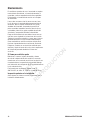
13. Connectthetransferswitch“UTILITY240VAC”
terminalstogenerator’s“240VAC”terminals
usinginstallersupplied300VACorgreater
wire, minimum #14 AWG conductors via
two-poleconnector supplied with generator.
WARNING Low voltage wire cannot be installed in
same conduit as power voltage wiring.
• Failure to follow above warning could cause personal
injury, damage and/or malfunction of equipment.
NOTICE Improper installation can cause damage to the
circuit boards and shorten their life. Installing circuit
boards in live circuits will damage the board and is not
covered by warranty. ALWAYS disconnect ALL sources of
power prior to servicing.
• Remove all power prior to installing this equipment.
Failure to do so could cause internal damage to the board
when making electrical connections.
• Turn generator to OFF position.
• Turn off utility power to the standby generator and
transfer switch.
WARNING Battery posts, terminals and related
accessories contain lead and lead compounds, chemicals
known to the State of California to cause cancer and
reproductive harm. Wash hands after handling.
33
240V
11
22
44
11
22
44
120V
120V
0
Neutral
Ground
To Transfer Switch
Line 1 Neutral
Ground
Line 2
Circuit
Breaker
NOT
FOR
REPRODUCTION

8 BRIGGSandSTRATTON.COM
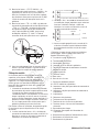
14. Connect “T/R” and “GND” terminals on transfer switch
control board (B) to the generator’s control panel (A)
“TxRx” and “TxRx GND” terminals using #18 AWG
twisted pair conductors, no greater than 200 ft in
length, 300 volt 75°C-90°C via ten-pole connector
supplied with generator.
15. Tighten all wire connections/fasteners to proper torque.
See label inside transfer switch enclosure for proper
torque values.
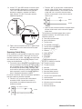
Supervisory Control Wiring
An air conditioner can be used with the supervisory contacts
on either terminals A-A or B-B. Terminals A-A can only be
used with supervisory control. Large loads can only be used
with contactor control on terminals B-B. Examples of each
system are described below.
1. The terminal strip on the transfer switch control board
has four connections for customer use. There are two
sets of “Normally Closed” contacts available. They will
be activated when generator power is required. These
can be used for supervisory control of large connected
loads on generator. Loads will be allowed to operate if
there is enough generator poweravailable.
For installer convenience, there are two wireways provided to
help keep supervisory load wires organized.
2. Terminals “A-A” on transfer switch control board
areratedfor24VAC.Connectthesecontactsin
series between air conditioner thermostat and air
conditionercontactor.
3. Terminals “B-B” on transfer switch control board are
ratedfor1Amp125VAC.Whenconnectedwithan
installer supplied contactor, it can be used to control
a large load, such as an electric hot water heater.
Contacts are connected in series with the contactor
control circuit.
4. Tighten all wire connections/fasteners to proper torque.
See label inside transfer switch enclosure for proper
torquevalues.
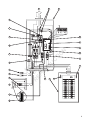
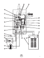
The illustration on the following page shows a typical
completed installation. Your actual layout will vary.
Illustration callouts are:
A - From utility watt-hour meter
B - Current transformers
C - Transfer switch
D - T/R and GND to Generator
E - Transfer switch control board
F - Supervisory contacts
G - Wireways
H - Neutral terminal
J - Neutral bus
K - Ground bus
L - Main distribution panel
M-UTILITY240VACtoGenerator
N - Two-pole connector
O - Ten-pole connector
P - Generator
R - Generator circuit breaker
S - Generator Neutral terminal
T - Generator Ground terminal
U - Transfer switch ground terminal
V-Loadconnection
W - Generator disconnect circuit breaker
X - Utility disconnect circuit breaker
Y - Utility connection
Z - Generator connection
B
B
Contactor
Neutral
120VAC
A
B
A
A
To air conditioner contactor
From air conditioner thermostat (yellow?)
24VAC
NOT
FOR
REPRODUCTION

9
G
E1
E2
N
240
VAC
L1
L2
N
G
L
1
L
2
N
A
D
E
F
H
T
J
U
N
Y
R
O
P
Z
L
W
K
V
G
S
C
B
M
X
NOT
FOR
REPRODUCTION

10 BRIGGSandSTRATTON.COM
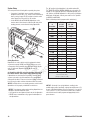
System Setup
You must perform the following before operating the system:
• Ifgeneratorisinstalledinanarearegularlysubjectedto
temperatures below 40°F (4°C), select a 50 second warm up
time by moving jumper JP2 (C) installed on transfer switch
control board from ‘20’ position to ‘50’position.
• SettheDPSW1(A) and DPSW2 (B) dipswitches on the
transfer switch control board to match the kW rating of the
standby generator, as described in SettingDipswitches.
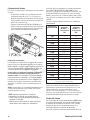
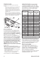
Setting Dipswitches
Dipswitches are used to adjust control board operation based
on generator capacity. DPSW1 and DPSW2 switches are set to
correspond to total system kW rating. Dipswitch DPSW1 (A) has
units of 1,000 watts; Dipswitch DPSW2 (B) has units of
10,000 watts.
Set dipswitches with utility and generator power removed from
the transfer switch to ensure proper control system operation.
If dipswitches are set when power is present at transfer switch,
a power reset needs to be performed before the new dipswitch
settings will take effect. Power reset is when all power is removed
from the transfer switch and then reintroduced after 30 seconds.
NOTICE An FC_8 will occur on standby generator control board if
dipswitches are not properly established as noted above.
The “On” position for the dipswitches is the switch number ON
THE TRANSFER SWITCH CONTROL BOARD, not on the switch. For
example, for an 18,000 watt generator, set DPSW2 dipswitch 10 to
“On” position. Set DPSW1 dipswitch 8 to “On” position. 10,000 plus
8000 equals 18,000 watts.
Set only one switch to “On” position
on DPSW1 andDPSW2.
Refer to following chart for proper switch selection(s).
NOTICE
Air density is less at high altitudes, resulting in less
available engine power. Specifically, engine power will decrease 3.5%
for each 1,000 feet (300 meters) above sea level and 1% for each 10°
F (5.6°C) above 77°F (25°C). Generators located in these conditions
must have the transfer switch programmed appropriately for this
power decrease.
NOTICE Use extreme caution when setting dipswitches or
damage to control board will result.
• Use a pencil or small piece of plastic to set the dipswitch.
• NEVERuseascrewdriveroranytypeofmetalobjectto
set dipswitches.
kW Rating
of
Generator
DPSW
#1 “ON”
Position
DPSW
#2 “ON”
Position
7kW 7 0
8kW 8 0
9kW 9 0
10kW* 0 10
11kW* 1 10
12kW 2 10
13kW* 3 10
14kW 4 10
15kW 5 10
16kW 6 10
17kW 7 10
18kW 8 10
19kW 9 10
20kW 0 20
30kW 0 30
45kW 5 40
48kW 8 40
50kW 0 50
60kW 0 60
* For generators with a rating that includes 500 Watts, round
down to next lowest rating
(example: 13.5 kW set to 13kW)
DPSW
1
DPSW2
JP2
A
B
C
NOT
FOR
REPRODUCTION

11
Controls
Other than a Manual Override lever, there are no operator
controls because this is an automatic transfer switch. The
manual override is to be used only by licensed professionals.
Information on handle use can be obtained by calling
Technical Service at 800-743-4115.
Operation
To select automatic transfer operation, do the following:
1. In transfer switch, set utility disconnect circuit breaker
to “ON” position.
2. In transfer switch, set generator disconnect circuit
breaker to “ON” position.
3. Install 15 Amp fuse in generator’s control panel.
4. Set generator’s circuit breaker to “ON” position.
5. Set generator’s system switch to “AUTO” position.
The system will now be in automatic operation mode.
When the generator is providing power to the transfer
switch, the transfer switch control board is constantly
monitoring generator power. If the air conditioner is called
to run, and there is sufficient generator power available,
the controller will close contacts “A-A” to air conditioner
contactor. Contacts “B B” will open before contacts A-A
close. If loads are too great for the generator, contacts A-A
and/or B-B will open. When air conditioning is not needed,
A-A will open. If enough power is available, B-B will close.
Enclosure Door
To open door, press the spring-load door lock to the right
and pull down on the door.
To close and latch door, push door closed against enclosure.
While in this position, push door upwards. This will cause
spring-load door lock to engage and latch door in place.
Enclosure door MUST be closed and latched at all times
except when system is being serviced.
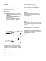
Testing the Automatic Transfer Switch
Turn the utility disconnect circuit breaker feeding the
transfer switch contactor to the “OFF” position. The
system’s automatic sequence will initiate. To return to utility
power, turn the utility disconnect circuit breaker to the
“ON”position.
Utility Fail
The generator senses when utility voltage is below
70percent of nominal. Engine start sequence is initiated
after 6 second time delay.
Engine Warm-Up
Time delay to allow for engine warm-up before transfer. Use
jumper on transfer switch control board to select delay of
20seconds or 50seconds.
Transfer
Transfer from utility to generator supply occurs after voltage
is above set levels. Minimum engine run time is 5 minutes
after transfer.
Utility Pickup
Voltagepickuplevelis80percentofnominalvoltage.
Retransfer
Retransfer from generator to utility power is approximately
10 seconds after utility voltage supply is above pickup level
and minimum run time is completed.
Engine Cool Down
Engine will run for 60 seconds after retransfer.
NOT
FOR
REPRODUCTION

12 BRIGGSandSTRATTON.COM
Maintenance
The transfer switch is designed to be maintenance free under
normal usage. However, inspection and maintenance checks
should be made on a regular basis. Maintenance will consist
mainly of keeping the transfer switch clean.
Visualinspectionsshouldbedoneatleastonceamonth.
Access to transfer switch must not be obstructed. Keep
3feet (92 cm) clearance around transfer switch. Check
for an accumulation of dirt, moisture and/or corrosion
on and around the enclosure, loose parts/hardware,
cracks and/or discoloration to insulation, and damaged or
discoloredcomponents.
Exercise the transfer switch at least once every three months
as described in Testing the Automatic Transfer Switch unless
a power outage occurs and home generator system has gone
through an automatic sequence. Allow generator to run for at
least 30 minutes.
Contact a licensed electrical professional to inspect and clean
the inside of the enclosure and other components of your
home generator system at least once a year.
When Calling for Assistance
You must have the Model Number and Serial Number from
the unit ID label at hand if it is necessary to contact a local
service center regarding service or repair of this unit. Obtain
this information from the unit ID label located on or inside
the enclosure.
To contact Briggs & Stratton call 800-743-4115, between
8:00 AM and 5:00 PM CT.
Installation Inspection
Before placing the system into service, inspect the entire
installation carefully.
NOT
FOR
REPRODUCTION

13
Notes
NOT
FOR
REPRODUCTION

14 BRIGGSandSTRATTON.COM
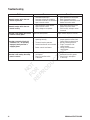
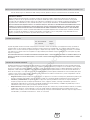
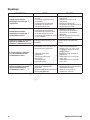
Troubleshooting
Problem Cause Correction
Au tomatic transfer switch does not
transfer to generator
1. Generator breaker open.
2. Generator voltage not acceptable.
3. Generator disconnect circuit breaker
open in transfer switch.
1. Reset generator circuit breaker.
2. Refer to generator manual.
3. Reset generator disconnect circuit
breaker in transfer switch.
Au tomatic transfer switch does not
transfer to utility
1. Utility disconnect circuit breaker
open in transfer switch.
2. Utility voltage not acceptable.
1. Reset utility disconnect circuit
breaker in transfer switch.
2. Wait for utility voltage to return
tonormal.
Ge nerator is still running after switch
transfers to utility power
Engine cool down period. Engine should stop after 1 minute.
Ge nerator or supervised loads (air
conditioner, etc.) are operating
improperly when generator is
supplyingpower
1. A-A or B-B contacts not
operatingcorrectly.
2. Too much load on generator.
3. Current transformer not connected.
4. Broken current transformer.
1. Check A-A or B-B contacts for
proper operation and/or check
control wiring to external load.
2. Decrease load to generator.
3. Plug CT connectors into
controlmodule.
4. Contact local authorized
servicecenter.
Ge nerator is still running after utility
power is restored
1. Minimum engine run time has
notelapsed.
2. Fuse(s) in transfer switch
isdefective.
1. Wait five minutes for transfer switch
to retransfer to utility power.
2. Check fuse(s) and replace
ifnecessary.
NOT
FOR
REPRODUCTION

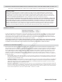
15
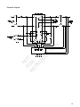
Schematic Diagram
NOT
FOR
REPRODUCTION

16 BRIGGSandSTRATTON.COM
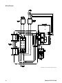
Wiring Diagram
Dashed lines show customer (field) connections
NOT
FOR
REPRODUCTION

17
Warranty
ABOUT YOUR WARRANTY
We welcome warranty repair and apologize to you for being inconvenienced. Any Authorized Service Dealer may perform warranty repairs. Most warranty
repairs are handled routinely, but sometimes requests for warranty service may not be appropriate. For example, warranty service would not apply if
equipment damage occurred because of misuse, lack of routine maintenance, shipping, handling, warehousing or improper installation. Similarly, the
warranty is void if the manufacturing date or the serial number on the equipment has been removed or the equipment has been altered or modified. During
the warranty period, the Authorized Service Dealer, at its option, will repair or replace any part that, upon examination, is found to be defective under normal
use and service. This warranty will not cover the following repairs and equipment:
• Normal Wear: Outdoor Power Equipment, like all mechanical devices, needs periodic parts and service to perform well. This warranty does not cover
repair when normal use has exhausted the life of a part or the equipment.
• Installation and Maintenance: This warranty does not apply to equipment or parts that have been subjected to improper or unauthorized
installation or alteration and modification, misuse, negligence, accident, overloading, improper maintenance, repair or storage so as, in our judgment,
to adversely affect its performance and reliability. This warranty also does not cover normal maintenance such as adjustments, cleaning and
fusereplacement.
• Other Exclusions: This warranty excludes wear items or damage or malfunctions resulting from accidents, abuse, modifications, alterations, or
improper servicing. Accessory parts are excluded from the product warranty. This warranty excludes failures due to acts of God and other force
majeure events beyond the manufacturers control. Also excluded is used, reconditioned, and demonstration equipment. 198180E, Rev. C, 12/31/2006
BRIGGS & STRATTON POWER PRODUCTS GROUP, LLC TRANSFER SWITCH OWNER WARRANTY POLICY
LIMITED WARRANTY
Briggs & Stratton Power Products Group, LLC will repair or replace, free of charge, any part(s) of the equipment that is defective in material or
workmanship or both. Transportation charges on product submitted for repair or replacement under this warranty must be borne by purchaser. This
warranty is effective for the time periods and subject to the conditions stated below. For warranty service, find the nearest Authorized Service Dealer in
our dealer locator map at BRIGGSandSTRATTON.COM.
THERE IS NO OTHER EXPRESS WARRANTY. IMPLIED WARRANTIES, INCLUDING THOSE OF MERCHANTABILITY AND FITNESS FOR A PARTICULAR
PURPOSE, ARE LIMITED TO ONE YEAR FROM PURCHASE, OR TO THE EXTENT PERMITTED BY LAW. ANY AND ALL IMPLIED WARRANTIES ARE
EXCLUDED. LIABILITY FOR INCIDENTAL OR CONSEQUENTIAL DAMAGES ARE EXCLUDED TO THE EXTENT EXCLUSION IS PERMITTED BY LAW. Some
states or countries do not allow limitations on how long an implied warranty lasts, and some states or countries do not allow the exclusion or limitation
of incidental or consequential damages, so the above limitation and exclusion may not apply to you. This warranty gives you specific legal rights and you
may also have other rights which vary from state to state or country to country.
Effective November 1, 2005 replaces all undated Warranties and all Warranties dated before November 1, 2005
The warranty period begins on the date of purchase by the first retail consumer or commercial end user, and continues for the period of time stated in the
table above. “Consumer use” means personal residential household use by a retail consumer. “Commercial use” means all other uses, including use for
commercial, income producing or rental purposes. Once equipment has experienced commercial use, it shall thereafter be considered as commercial use for
purposes of this warranty. Equipment used for prime power in place of utility are not applicable to this warranty.
NOWARRANTYREGISTRATIONISNECESSARYTOOBTAINWARRANTYONBRIGGS&STRATTONPRODUCTS.SAVEYOURPROOFOFPURCHASE
RECEIPT.IFYOUDONOTPROVIDEPROOFOFTHEINITIALPURCHASEDATEATTHETIMEWARRANTYSERVICEISREQUESTED,THEMANUFACTURING
DATE OF THE PRODUCT WILL BE USED TO DETERMINE THE WARRANTY PERIOD.
3 years
None
Consumer Use
Commercial Use
WARRANTY PERIOD
NOT
FOR
REPRODUCTION

18 BRIGGSandSTRATTON.COM
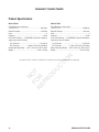
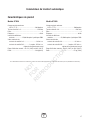
Product Specifications
Model 071036
Rated Maximum Load Current*
(at 25°C/77°F) ......................................................200 Amps
RatedACVoltage .................................................... 250Volts
Poles .................................................................................... 2
Frequency ..................................................................... 60 Hz
Fault Current Rating ....... 25,000 RMS Symmetrical Amperes
Supervisory Contacts Rating:
A-A Terminals.................................................... 24VoltAC
B-B Terminals.................... 1Amp,125VoltAC,PilotDuty
Normal Operating Range .... -20°F (-28.8°C) to 104°F (40°C)
Weight ............................................................63 lbs. (28 kg)
Model 071045
Rated Maximum Load Current*
(at 25°C/77°F) ......................................................100 Amps
RatedACVoltage .................................................... 250Volts
Poles .................................................................................... 2
Frequency ..................................................................... 60 Hz
Fault Current Rating ....... 25,000 RMS Symmetrical Amperes
Supervisory Contacts Rating:
A-A Terminals.................................................... 24VoltAC
B-B Terminals.................... 1Amp,125VoltAC,PilotDuty
Normal Operating Range .... -20°F (-28.8°C) to 104°F (40°C)
Weight ............................................................59 lbs (27 kg).
Automatic Transfer Switch
*This transfer switch is certified in accordance with UL (Underwriters Laboratories) 1008 (transfer switch equipment).
NOT
FOR
REPRODUCTION

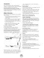
Generator Systems
Manual de instalación y del operario
100/200 Amperios Interruptor
de transferencia automática
con módulo de control de energía
eléctrica de CA™
NOT
FOR
REPRODUCTION

2 BRIGGSandSTRATTON.COM
Gracias por comprar este conectador automático de Briggs & Stratton® Power Products. Este producto está diseñado para
utilizarse con generadores de reserva domésticos específicos y puede no funcionar con generadores producidos por otros
fabricantes. Recurra a un electricista profesional cualificado para determinar la aplicabilidad de este equipo en generadores
fabricados por terceros. Si se utiliza y mantiene de acuerdo con las instrucciones de este manual, su sistema le proporcionará
muchos años de funcionamiento fiable.
Este manual contiene información de seguridad para que usted conozca los peligros y riesgos propios de este sistema y
cómo evitarlos. Se ha realizado el máximo esfuerzo para que la instalación resulte segura, sencilla y económica. Debido a que
cada instalación es única, es imposible conocer y recomendar todos los procedimientos y métodos posibles para efectuarla.
No conocemos todos los riesgos y/o resultados posibles de cada método o procedimiento existente. Es importante que lea
y comprenda perfectamente estas instrucciones antes de intentar instalar o utilizar este equipo. Guarde estas instrucciones
para futuras consultas.
Este el conectador requiere instalación profesional antes de utilizarse. Consulte las instrucciones sobre los procedimientos
de instalación en la sección Instalación del presente manual. Los conectador sólo deben ser instalados por electricistas con
licencia. Las instalaciones deben cumplir estrictamente la totalidad de los códigos, estándares y regulaciones federales,
estatales y locales vigentes. El instalador debe seguir las instrucciones detalladamente.
Ubicación
Nunca debe ir demasiado lejos para encontrar el soporte y servicio de Briggs & Stratton para su sistema. Consulte las
Páginas Amarillas. Existen múltiples distribuidores de servicio autorizados que ofrecen un servicio de calidad. También puede
comunicarse con el Servicio técnico por teléfono al 800-743 4115 de 8:00 a. m. a 5:00 p. m. Hora del Centro, o a través de
Internet en BRIGGSandSTRATTON.COM.
Para futuras consultas
Llene la siguiente información y conserve su factura para facilitar la identificación de la unidad en caso de que surjan
problemas relacionados con la compra en el futuro.
Conectador automático
Número de modelo
Revisión
Número de serie
Fecha de compra
Copyright © 2012. Briggs & Stratton Power Products Group, LLC
Milwaukee, WI, USA. Reservados todos los derechos.
Briggs & Stratton Power Products es una marca
registradas de Briggs & Stratton Corporation
Milwaukee, WI, USA
NOT
FOR
REPRODUCTION
La page charge ...
La page charge ...
La page charge ...
La page charge ...
La page charge ...
La page charge ...
La page charge ...
La page charge ...
La page charge ...
La page charge ...
La page charge ...
La page charge ...
La page charge ...
La page charge ...
La page charge ...
La page charge ...
La page charge ...
La page charge ...
La page charge ...
La page charge ...
La page charge ...
La page charge ...
La page charge ...
La page charge ...
La page charge ...
La page charge ...
La page charge ...
La page charge ...
La page charge ...
La page charge ...
La page charge ...
La page charge ...
-
 1
1
-
 2
2
-
 3
3
-
 4
4
-
 5
5
-
 6
6
-
 7
7
-
 8
8
-
 9
9
-
 10
10
-
 11
11
-
 12
12
-
 13
13
-
 14
14
-
 15
15
-
 16
16
-
 17
17
-
 18
18
-
 19
19
-
 20
20
-
 21
21
-
 22
22
-
 23
23
-
 24
24
-
 25
25
-
 26
26
-
 27
27
-
 28
28
-
 29
29
-
 30
30
-
 31
31
-
 32
32
-
 33
33
-
 34
34
-
 35
35
-
 36
36
-
 37
37
-
 38
38
-
 39
39
-
 40
40
-
 41
41
-
 42
42
-
 43
43
-
 44
44
-
 45
45
-
 46
46
-
 47
47
-
 48
48
-
 49
49
-
 50
50
-
 51
51
-
 52
52


Simplicity 040362-00 Manuel utilisateur
- Catégorie
- Groupes électrogènes
- Taper
- Manuel utilisateur
dans d''autres langues
- English: Simplicity 040362-00 User manual
- español: Simplicity 040362-00 Manual de usuario