Maytag Duet Steam WGD9270X Installation Instructions Manual
- Catégorie
- Sèche-linge
- Taper
- Installation Instructions Manual

1
W10240584B
W10240585B-SP
GAS DRYER INSTALLATION INSTRUCTIONS
CANADIAN ELECTRIC DRYER INSTRUCTIONS
INSTRUCTIONS POUR L'INSTALLATION DE LA SÉCHEUSE
À GAZ (É.-U. ET CANADA)
ET ÉLECTRIQUE (CANADA UNIQUEMENT)
Table of Contents
DRYER SAFETY ................................................................2
INSTALLATION REQUIREMENTS ....................................4
Tools and Parts .................................................................... 4
Location Requirements ...................................................... 5
Electric Dryer Power Hookup-Canada Only ..................... 7
Gas Dryer Power Hookup ................................................... 8
INSTALLATION INSTRUCTIONS .............................................. 10
Venting Requirements ....................................................... 10
Plan Vent System ............................................................... 11
Install Vent System ............................................................ 12
Install Leveling Legs ......................................................... 12
Make Gas Connection ...................................................... 13
Connect Inlet Hose............................................................ 13
Connect Vent ..................................................................... 15
Level Dryer ......................................................................... 15
Complete Installation Checklist ....................................... 16
Door Reversal .................................................................... 16
Troubleshooting ................................................................. 16
INSTALLATION NOTES
Date of purchase: _________________________________
Date of installation: _______________________________
Installer: ________________________________________
Model number: ___________________________________
Serial number: ___________________________________
Date d'achat : _____________________________________
Date d'installation : ________________________________
Installateur : ______________________________________
Numéro de modèle : ________________________________
Numéro de série : __________________________________
NOTES CONCERNANT L'INSTALLATION
Table des matières
SÉCURITÉ DE LA SÉCHEUSE ....................................... 17
EXIGENCES D'INSTALLATION ...................................... 19
Outillage et pièces ............................................................ 19
Exigences d'emplacement ............................................... 20
Raccordement à l'alimentation électrique de
la sécheuse électrique - Canada seulement ................. 22
Raccordement d'une sécheuse à gaz ............................. 23
INSTRUCTIONS POUR L'INSTALLATION ............................... 25
Exigences concernant l'évacuation ................................ 25
Planication du système d'évacuation ........................... 26
Installation du circuit d'évacuation ................................. 27
Installation des pieds de nivellement .............................. 28
Raccordement au gaz ....................................................... 28
Raccordement du tuyau d'arrivée d'eau ......................... 29
Raccordement du conduit d'évacuation ......................... 30
Réglage de l'aplomb de la sécheuse ............................... 31
Achever l'installation - liste de vérication ..................... 31
Inversion de la porte ......................................................... 32
Dépannage ......................................................................... 32

2
DRYER SAFETY
You
You can be killed or seriously injured if you don't immediately
can be killed or seriously injured if you don't
follow
All safety messages will tell you what the potential hazard is, tell you how to reduce the chance of injury, and tell you what can
happen if the instructions are not followed.
Your safety and the safety of others are very important.
We have provided many important safety messages in this manual and on your appliance. Always read and obey all safety
messages.
This is the safety alert symbol.
This symbol alerts you to potential hazards that can kill or hurt you and others.
All safety messages will follow the safety alert symbol and either the word “DANGER” or “WARNING.”
These words mean:
follow instructions.
instructions.
DANGER
WARNING

3
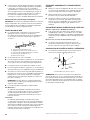
WARNING: Gas leaks cannot always be detected by smell.
Gas suppliers recommend that you use a gas detector approved by UL or CSA.
For more information, contact your gas supplier.
If a gas leak is detected, follow the “What to do if you smell gas” instructions.
WARNING: For your safety, the information in this manual must be followed to minimize
the risk of re or explosion, or to prevent property damage, personal injury, or death.
– Do not store or use gasoline or other ammable vapors and liquids in the vicinity of this
or any other appliance.
– WHAT TO DO IF YOU SMELL GAS:
•
Do not try to light any appliance.
•
Do not touch any electrical switch; do not use any phone in your building.
•
Immediately call your gas supplier from a neighbor's phone. Follow the gas supplier's
instructions.
•
If you cannot reach your gas supplier, call the re department.
– Installation and service must be performed by a qualied installer, service agency, or
the gas supplier.
•
Clear the room, building, or area of all occupants.
IMPORTANT: The gas installation must conform with local codes, or in the absence of local codes, with the National Fuel Gas
Code, ANSI Z223.1/NFPA 54 or the Canadian Natural Gas and Propane Installation Code, CSA B149.1.
The dryer must be electrically grounded in accordance with local codes, or in the absence of local codes, with the National
Electrical Code, ANSI/NFPA 70 or Canadian Electrical Code, CSA C22.1.
In the State of Massachusetts, the following installation instructions apply:
� Installations and repairs must be performed by a qualied or licensed contractor, plumber, or gastter qualied or licensed by
the State of Massachusetts.
� If using a ball valve, it shall be a T-handle type.
� A exible gas connector, when used, must not exceed 3 feet.

4
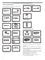
TOOLS AND PARTS
Gather the required tools and parts before starting installation.
Tools needed for all installations:
Level
Tape measure
Pliers
Parts package is located in dryer drum. Check that all parts
are included.
NOTE: If installing dryer on pedestal, do not use leveling legs.
Check local codes. Check existing electrical supply and venting.
See “Electrical Requirements” and “Venting Requirements”
before purchasing parts.
Check code requirements. Some codes limit, or do not permit,
installing dryer in garages, closets, mobile homes, or sleeping
quarters. Contact your local building inspector.
Optional Equipment: (Not supplied with dryer)
Refer to your Use and Care Guide for information about
accessories available for your dryer.
Parts supplied (all models):
Flat-blade screwdriver #2 Phillips screwdriver
Adjustable wrench that
opens to 1" (25 mm) or
hex-head socket wrench
Wire stripper (direct wire
installations)
Tin snips (new vent
installations)
Caulking gun and compound
(for installing new exhaust vent)
Vent clamps
1/4" nut driver
(recommended)
Leveling legs (4)
Tools needed for gas installations:
8" or 10" pipe wrench
8" or 10" adjustable wrench
(for gas connections)
Pipe-joint compound
resistant to LP gas
Utility knife
“Y” connector Short inlet hose
Long inlet hose Rubber washer
Parts supplied (steam models):
INSTALLATION REQUIREMENTS

5
LOCATION REQUIREMENTS
You will need:
A location allowing for proper exhaust installation. ■
See “Venting Requirements.”
If using power supply cord, a grounded electrical outlet ■
located within 2 ft. (610 mm) of either side of dryer.
See “Electrical Requirements.”
Floor must support dryer weight of 200 lbs. (90.7 kg). ■
Also consider weight of companion appliance.
Cold water faucets located within 4 ft. (1.2 m) of the water ll ■
valves, and water pressure of 20-100 psi (137.9-689.6 kPa).
You may use the water supply for your washer using the “Y”
connector and short hose (if needed) which are provided.
20-100 psi (138-690 kPa) for best performance. ■
Level oor with maximum slope of 1" (25 mm) under entire ■
dryer. If slope is greater than 1" (25 mm), install Extended
Dryer Feet Kit, Part Number 279810. If not level, clothes
may not tumble properly and automatic sensor cycles may
not operate correctly.
For garage installation, place dryer at least 18" (460 mm) ■
above oor. If using a pedestal, you will need 18" (460 mm)
to bottom of dryer.
For each arrangement, consider allowing more space for ease
of installation and servicing; spacing for companion appliances
and clearances for walls, doors, and oor moldings. Space
must be large enough to allow door to fully open. Add spacing
on all sides of dryer to reduce noise transfer. If a closet door
or louvered door is installed, top and bottom air openings
in door are required.
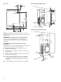
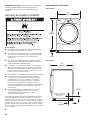
DRYER DIMENSIONS
Front view:
27"
(686 mm)
3
/4"
(18 mm)
35
3
/8"
(899 mm)
Side view:
3
1
/2"
(89 mm)
6
7
/8"
(175 mm)
29"
(736 mm)
Optional side
exhaust vent
location

6
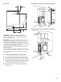
Back view:
Electric
6
1
/4"
(159 mm)
28
1
/8"
(715 mm)
3
1
/2"
(89 mm)
14"
(358 mm)
Back exhaust
vent location
NOTE: Most installations require a minimum of 5" (127 mm)
clearance behind dryer for exhaust vent with elbow. See “Venting
Requirements.”
IMPORTANT: Do not operate, install, or store dryer where
it will be exposed to water, weather, or at temperatures below
45° F (7° C). Lower temperatures may cause dryer not to
shut off at end of automatic sensor cycles, resulting in longer
drying times.
Installation spacing for recessed area or closet
installation
All dimensions show recommended spacing allowed, with tested
spacing of 0" (0 mm) clearance on sides and rear.
Additional spacing should be considered for ease of ■
installation and servicing.
Additional clearances might be required for wall, door, and ■
oor moldings.
Additional spacing should be considered on all sides of the ■
dryer to reduce noise transfer.
For closet installation, with a door, minimum ventilation ■
openings in the top and bottom of the door are required.
Louvered doors with equivalent ventilitation openings are
acceptable.
Companion appliance spacing should also be considered. ■
Closet installation (dryer only):
24 in.
2
(155 cm
2
)
48 in.
2
(310 cm
2
)
1"
(25 mm)
1"
(25 mm)
4"
(102 mm)
3"
(76 mm)
34" recommended
(864 mm)
18" min.
(457 mm)
3"
(76 mm)
Cabinet installation (dryer only):
1"
(25 mm)
1"
(25 mm)
4"
(102 mm)
7"
(178 mm)
18"
(460 mm)

7
Closet Installation (stacked washer and dryer):
1"
(25 mm)
1"
(25 mm)
5
1
/2"
(140 mm)
24 in.
2
(155 cm
2
)
48 in.
2
(310 cm
2
)
3"
(76 mm)
3"
(76 mm)
6"
(152 mm)
76"
(1930 mm)
Custom under counter installation (dryer only):
1"
(25 mm)
1"
(25 mm)
39" min.
(990 mm)
NOTE: Some models not recommended for undercounter
installation.
Mobile home - Additional installation requirements:
This dryer is suitable for mobile home installations.
The installation must conform to the Manufactured
Home Construction and Safety Standard, Title 24 CFR,
Part 3280 (formerly the Federal Standard for Mobile home
construction and Safety, Title 24, HUD Part 280) or Standard
CAN/CSA-Z240 MH.
Mobile home installations require:
All dryers:
Metal exhaust system hardware, available for purchase ■
from your dealer. For further information, see “Assistance
or Service” section in your Use and Care Guide.
Special provisions must be made in mobile homes to ■
introduce outside air into dryer. Openings (such as a
nearby window) should be at least twice as large as
dryer exhaust opening.
For gas dryers mobile home installations:
Mobile Home Installation Hold-down Kit Part Number ■
346764 is available to order. For further information, see
"Assistance or Service" section in your Use and Care Guide.
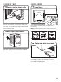
ELECTRIC DRYER
POWER HOOKUP- CANADA ONLY
ELECTRICAL REQUIREMENTS
WARNING
Electrical Shock Hazard
Plug into a grounded 4 prong outlet.
Failure to do so can result in death or electrical shock.
It is your responsibility:
To contact a qualied electrical installer. ■
To be sure that the electrical connection is adequate and in ■
conformance with Canadian Electrical Code, C22.1-latest
edition and all local codes. A copy of above codes standard
may be obtained from: Canadian Standards Association,
178 Rexdale Blvd., Toronto, ON M9W 1R3 CANADA.
To supply the required 4 wire, single phase, 120/240 volt, ■
60 Hz, AC only electrical supply on a separate 30-amp
circuit, fused on both sides of the line. A time-delay fuse or
circuit breaker is recommended. Connect to an individual
branch circuit.
This dryer is equipped with a CSA International Certied ■
Power Cord intended to be plugged into a standard 14-30R
wall receptacle. The cord is 5 ft. (1.52 m) long. Be sure wall
receptacle is within reach of dryer’s nal location.
4-wire receptacle (14-30R)
If using a replacement power supply cord, it is recommended that
you use Power Supply Cord Replacement Part Number 9831317.

8
For further information, please reference service numbers located
in “Assistance or Service” section of your Use and Care Guide.
GROUNDING INSTRUCTIONS
SAVE THESE INSTRUCTIONS
�
For a grounded, cord-connected dryer:
This dryer must be grounded. In the event of malfunction or
breakdown, grounding will reduce the risk of electric shock
by providing a path of least resistance for electric current.
This dryer is equipped with a cord having an equipment-
grounding conductor and a grounding plug. The plug must
be plugged into an appropriate outlet that is properly
installed and grounded in accordance with all local codes
and ordinances.
WARNING: Improper connection of the equipment-
grounding conductor can result in a risk of electric shock.
Check with a qualied electrician or service representative
or personnel if you are in doubt as to whether the dryer is
properly grounded. Do not modify the plug provided with
the dryer: if it will not t the outlet, have a proper outlet
installed by a qualied electrician.
GAS DRYER POWER HOOKUP
ELECTRICAL REQUIREMENTS
Electrical Shock Hazard
Plug into a grounded 3 prong outlet.
Do not remove ground prong.
Do not use an adapter.
Do not use an extension cord.
Failure to follow these instructions can result in death,
re, or electrical shock.
WARNING
120 Volt, 60 Hz, AC only, 15- or 20- amp fused electrical ■
supply is required. A time-delay fuse or circuit breaker is
recommended. It is also recommended that a separate
circuit serving only this dryer be provided.
GROUNDING INSTRUCTIONS
SAVE THESE INSTRUCTIONS
�
For a grounded, cord-connected dryer:
This dryer must be grounded. In the event of malfunction or
breakdown, grounding will reduce the risk of electric shock
by providing a path of least resistance for electric current.
This dryer is equipped with a cord having an equipment-
grounding conductor and a grounding plug. The plug must
be plugged into an appropriate outlet that is properly
installed and grounded in accordance with all local codes
and ordinances.
WARNING:
Improper connection of the equipment-
grounding conductor can result in a risk of electric shock.
Check with a qualied electrician or service representative
or personnel if you are in doubt as to whether the dryer is
properly grounded. Do not modify the plug provided with
the dryer: if it will not t the outlet, have a proper outlet
installed by a qualied electrician.
GAS SUPPLY REQUIREMENTS
WARNING
Explosion Hazard
Use a new CSA International approved gas supply line.
Install a shut-off valve.
Securely tighten all gas connections.
If connected to LP, have a qualied person make sure
gas pressure does not exceed 13" (330 mm) water
column.
Examples of a qualied person include:
licensed heating personnel,
authorized gas company personnel, and
authorized service personnel.
Failure to do so can result in death, explosion, or re.
GAS TYPE
Natural Gas:
This dryer is equipped for use with Natural gas. It is design-
certied by CSA International for LP (propane or butane) gases
with appropriate conversion.

9
Your dryer must have the correct burner for the type of gas ■
in your home. Burner information is located on the rating
plate in the door well of your dryer. If this information does
not agree with the type of gas available, contact your dealer
or call the phone numbers referenced in the “Assistance or
Service” section of your Use and Care Guide.
LP Gas Conversion:
IMPORTANT: Conversion must be made by a qualied
technician.
No attempt shall be made to convert the dryer from the gas
specied on the model/serial rating plate for use with a different
gas without consulting your gas company.
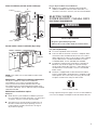
GAS SUPPLY LINE
Must include 1/8" NPT minimum plugged tapping accessible ■
for test gauge connection, immediately upstream of the gas
connection to the dryer.
A
B
E
D
C
A. 3/8" exible gas connector
B. 3/8" pipe to are adapter tting
C. 1/8" NPT minimum plugged tapping
D. 1/2" NPT gas supply line
E. Gas shutoff valve.
1/2" IPS pipe is recommended. ■
3/8"approved aluminum or copper tubing is acceptable for ■
lengths under 20 ft. (6.1 m) if local codes and gas supplier
permit.
If you are using Natural gas, do not use copper tubing. ■
Lengths over 20 ft. (6.1 m) should use larger tubing and ■
a different size adapter tting.
If your dryer has been converted to use LP gas, 3/8" LP ■
compatible copper tubing can be used. If the total length of
the supply line is more than 20 ft. (6.1 m), use larger pipe.
NOTE: Pipe-joint compounds that resist the action of LP gas
must be used. Do not use TEFLON
®†
tape.
Must include shut-off valve ■
In the U.S.A.:
An individual manual shut-off valve must be installed within
six (6) ft. (1.8 m) of the dryer in accordance with the National
Fuel Gas Code, ANSI Z223.1. The location should be easy to
reach for opening and closing.
In Canada:
An individual manual shut-off valve must be installed in
accordance with the B149.1, Natural Gas and Propane
Installation Code. It is recommended that an individual
manual shutoff valve be installed within six (6) ft. (1.8 m) of
the dryer. The location should be easy to reach for opening
and closing.
GAS SUPPLY CONNECTION REQUIREMENTS
Use an elbow and a 3/8" are x 3/8" NPT adapter tting ■
between the exible gas connector and the dryer gas pipe,
as needed to avoid kinking.
Use only pipe-joint compound. Do not use TEFLON ■
®†
tape.
This dryer must be connected to the gas supply line with a ■
listed exible gas connector that complies with the standard
for connectors for gas appliances, ANSI Z21.24 or CSA 6.10.
BURNER INPUT REQUIREMENTS
Elevations above 10,000 ft. (3,048 m):
When installed above 10,000 ft. (3,048 m) a 4% reduction ■
of the burner Btu rating shown on the model/serial number
plate is required for each 1,000 ft. (305 m) increase in
elevation.
Gas supply pressure testing
The dryer must be disconnected from the gas supply piping ■
system during pressure testing at pressures greater than
1/2 psi.
DRYER GAS PIPE
The gas pipe that comes out through the rear of your dryer ■
has a 3/8" male pipe thread.
A
*6¼"
(159 mm)
1½"
(38 mm)
A. 3/8" NPT dryer pipe
*NOTE: If the dryer is mounted on a pedestal, the gas pipe height
must be an additional 10" (254 mm) or 15.5" (394 mm) from the
oor, depending on the pedestal model. For a garage installation,
the gas pipe height must be an additional 18" (460 mm) from
the oor.
†®TEFLON is a registered trademark of E.I. Dupont De Nemours and Company.
A. 3/8" NPT dryer pipe

10
VENTING REQUIREMENTS
WARNING
Fire Hazard
Use a heavy metal vent.
Do not use a plastic vent.
Do not use a metal foil vent.
Failure to follow these instructions can result in death
or re.
WARNING: To reduce the risk of re, this dryer MUST BE
EXHAUSTED OUTDOORS.
IMPORTANT: Observe all governing codes and ordinances.
Dryer exhaust must not be connected into any gas vent,
chimney, wall, ceiling, attic, crawlspace, or a concealed space
of a building. Only rigid or exible metal vent shall be used for
exhausting.
Rigid metal vent:
Recommended for best drying performance and to prevent ■
crushing and kinking.
Flexible metal vent: (Acceptable only if accessible to clean)
Must be fully extended and supported in nal dryer location. ■
Remove excess to avoid sagging and kinking that may ■
result in reduced airow and poor performance.
Do not install in enclosed walls, ceilings, or oors. ■
The total length should not exceed 7 ■
3
/
4
ft. (2.4 m).
NOTE: If using an existing vent system, clean lint from entire
length of the system and make sure exhaust hood is not plugged
with lint. Replace plastic or metal foil vents with rigid metal or
exible metal vents. Review Vent system chart and if necessary,
modify existing vent system to achieve best drying performance.
Only a 4" (102 mm) heavy metal exhaust ■
vent and clamps may be used.
Do not use plastic or metal foil vent. ■
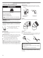
Exhaust hoods:
Must be at least 12" (305 mm) from ground or any object ■
that may obstruct exhaust (such as owers, rocks, bushes,
or snow).
Elbows:
45° elbows provide better airow than 90° elbows. ■
Good Better
Clamps:
Use clamps to seal all joints. ■
Exhaust vent must not be connected or secured with screws ■
or other fastening devices that extend into interior of duct
and catch lint. Do not use duct tape.
Improper venting can cause moisture and lint to collect
indoors, which may result in:
Moisture damage to woodwork, furniture, paint, wallpaper,
carpets, etc.
Housecleaning problems and health problems.
Vent products can be purchased from your dealer. For more
information, see “Assistance or Service” section in your Use and
Care Guide.
4"
(102 mm)
4"
(102 mm)
B
A
4"
(102 mm)
2½"
(64 mm)
C
Recommended styles:
A. Louvered hood
B. Box hood
Acceptable styles:
C. Angled hood
INSTALLATION INSTRUCTIONS

11
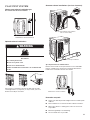
PLAN VENT SYSTEM
Choose your exhaust installation type
Recommended exhaust installation:
Standard rear-exhaust hook-up
Optional exhaust installations:
WARNING
Fire Hazard
Use a heavy metal vent.
Do not use a plastic vent.
Do not use a metal foil vent.
Failure to follow these instructions can result in death
or re.
Dryer may be converted to exhaust out right side, left side,
or through bottom. If you prefer, you may contact your local
dealer to have dryer converted.
Alternate exhaust installations: (for close clearance)
Over-the-top installation (also available
with one offset elbow)
Periscope installation
Special provisions for mobile homes:
Exhaust vent must be securely fastened to a noncombustible
portion of mobile home and must not terminate beneath the
mobile home. Terminate exhaust vent outside.
Mobile home exhaust installation
Determine vent path:
Select route that will provide straightest and most direct path ■
outdoors.
Plan installation to use fewest number of elbows and turns. ■
When using elbows or making turns, allow as much room ■
as possible.
Bend vent gradually to avoid kinking. ■
Use as few 90° turns as possible. ■

12
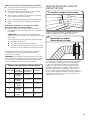
Vent system chart
Number of
90° elbows
Type
of vent
Box/louvered
hoods
Angled
hoods
1
4
3
2
0
Rigid metal
Rigid metal
Rigid metal
Rigid metal
Rigid metal
64 ft. (20 m)
54 ft. (16.5 m)
44 ft. (13.4 m)
35 ft. (10.7 m)
27 ft. (8.2 m)
58 ft. (17.7 m)
48 ft. (14.6 m)
38 ft. (11.6 m)
29 ft. (8.8 m)
21 ft. (6.4 m)
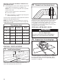
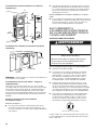
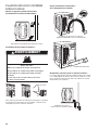
INSTALL VENT SYSTEM
12" min.
(305 mm)
12" min.
(305 mm)
Install exhaust hood
1.
Install exhaust hood and use caulking compound to seal
exterior wall opening around exhaust hood.
Prepare dryer for leveling legs
3.
To avoid damaging oor, use a large at piece of cardboard
from dryer carton; place under entire back edge of dryer.
Firmly grasp dryer body (not console panel) and gently lay
dryer down on cardboard.
INSTALL LEVELING LEGS
WARNING
Excessive Weight Hazard
Use two or more people to move and install dryer.
Failure to do so can result in back or other injury.
Connect vent to exhaust hood
2.
Vent must t over the exhaust hood. Secure vent to exhaust
hood with 4" (102 mm) clamp. Run vent to dryer location
using straightest path possible. Avoid 90° turns. Use clamps
to seal all joints. Do not use duct tape, screws, or other
fastening devices that extend into interior of vent to secure
vent, because they can catch lint.
The Vent system chart provides venting requirements that will
help achieve best drying performance.
NOTE: Side and bottom exhaust installation have a 90° turn
inside the dryer. To determine maximum exhaust length, add
on 90° turn to the chart.
Determine vent length and elbows needed for best
drying performance:
Use following Vent system chart to determine type of vent ■
material and hood combinations acceptable to use.
NOTE: Do not use vent runs longer than those specied
in Vent system chart.
Exhaust systems longer than those specied will:
Shorten life of dryer. ■
Reduce performance, resulting in longer drying times ■
and increased energy usage.

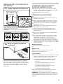
13
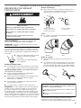
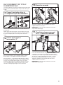
Screw in leveling legs
4.
diamond
m
arking
Examine leveling legs, nd diamond marking. Screw legs into
leg holes by hand, use a wrench to nish turning legs until
diamond marking is no longer visible.
Now stand the dryer on its feet. Slide the dryer until it is
close to its nal location. Leave enough room to connect the
exhaust vent.
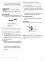
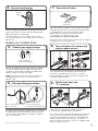
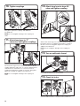
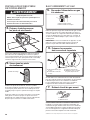
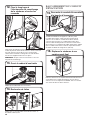
CONNECT INLET HOSE
The dryer must be connected to the cold water faucet using the
new inlet hoses. Do not use old hoses.
Turn cold water off, remove and
replace rubber washer
8.
Turn cold water faucet off and remove washer inlet hose.
Check and see if rubber washer is in the “Y” connector.
Remove old rubber washer from inlet hose and replace with
new rubber washer provided.
Attach short hose and
“Y” connector
9.
If space permits, attach the brass female end of the “Y”
connector to the cold water faucet. See gure A.
If “Y” connector cannot be attached directly to the cold water
faucet, the short hose must be used. See gure B. Attach
short hose to cold water faucet. Screw on coupling by hand
until it is seated on faucet. Then attach “Y” connector to
brass male end of the short hose. Screw on coupling by hand
until it is seated on connector.
A B
A
B
Connect gas supply to dryer
5.
Remove red cap from gas pipe. Using a wrench to tighten,
connect gas supply to dryer. Use pipe-joint compound
on threads of all non-ared male ttings. If exible metal
tubing is used, be sure there are no kinks.
NOTE: For LP gas connections, you must use pipe-joint
compound resistant to action of LP gas. Do not use
TEFLON
®†
tape.
A. Flared male tting
B. Non-ared male tting
A
B
C
D
Plan pipe tting connection
6.
A combination of pipe ttings must be used to connect dryer
to existing gas line. A recommended connection is shown.
Your connection may be different, according to supply line
type, size, and location.
A. 3/8" exible gas connector
B. 3/8" dryer pipe
C. 3/8" to 3/8" pipe elbow
D. 3/8" pipe-to-are adapter tting
A
B
Open shut-off valve
7.
Open shut-off valve in supply line; valve is open when handle
is parallel to gas pipe. Then, test all connections by brushing
on an approved noncorrosive leak-detection solution.
Bubbles will show a leak. Correct any leaks found.
A. Closed valve
B. Open valve
MAKE GAS CONNECTION
†®TEFLON is a registered trademark of E.I. Dupont De Nemours and Company.

14
Tighten couplings
10.
Using pliers, tighten the couplings with additional
two-thirds turn.
NOTE: Do not overtighten. Damage to the coupling can
result.
Attach long hose to “Y”
connector and tighten couplings
11.
One end of the long hose has a wire mesh strainer inside the
coupling. Attach this end to the “Y” connector. Attach washer
cold inlet hose to other side of “Y” connector. Screw on
coupling by hand until it is seated on connector. Using pliers,
tighten the couplings an additional two-thirds turn.
NOTE: Do not overtighten. Damage to the coupling can
result.
Attach long hose to dryer ll
valve and tighten coupling
12.
Attach other end of long hose to ll valve at bottom of dryer
back panel. Screw on coupling by hand until it is seated on
ll valve connector. Using pliers, tighten the couplings an
additional two-thirds turn.
NOTE: Do not overtighten. Damage to the coupling can
result.
Turn on cold water faucet
13.
Check that the water faucets are turned on.
Check for leaks
14.
Check for leaks around “Y” connector, faucet, and hoses.
A B

15
LEVEL DRYER
Level Dryer
17.
Not Level LEVEL Not Level
Check levelness of dryer from side to side. Repeat from
front to back.
NOTE: The dryer must be level for the moisture sensing system
to operate correctly.
Place
level here
Tighten and adjust leveling legs
18.
If dryer is not level, prop up using a wood block, use wrench
to adjust legs up or down, and check again for levelness.
Once legs are level, make sure all four legs are snug against
the ground before tightening them.
CONNECT VENT
Connect vent to exhaust outlet
15.
Move dryer to nal location
16.
Using a 4" (102 mm) clamp, connect vent to exhaust outlet
in dryer. If connecting to existing vent, make sure vent is
clean. Dryer vent must t over dryer exhaust outlet and inside
exhaust hood. Check that vent is secured to exhaust hood
with a 4" (102 mm) clamp.
Move dryer to nal location. Avoid crushing or kinking vent.
After dryer is in place, remove corner posts and cardboard
from under the dryer.

16
COMPLETE INSTALLATION
CHECKLIST
q
Check that all parts are now installed. If there is an extra
part, go back through steps to see what was skipped.
q
Check that you have all of your tools.
q
Dispose of/recycle all packaging materials.
q
Be sure the water faucets are on.
q
Check for leaks around “Y” connector, faucet, and hoses.
q
Check dryer’s nal location. Be sure vent is not crushed
or kinked.
q
Check that dryer is level. See “Level Dryer”.
q
Remove lm on console and any tape remaining on dryer.
q
Wipe dryer drum interior thoroughly with a damp cloth to
remove any dust.
q
Read “Dryer Use” in your Use and Care Guide.
q
If you live in a hard water area, use of a water softener is
recommended to control the buildup of scale through the
water system in the dryer. Over time, the buildup of lime
scale may clog different parts of the water system, which will
reduce product performance. Excessive scale buildup may
lead to the need for certain part replacement or repair.
Electric Models:
q
Plug into a grounded outlet.
Gas Models:
q
Check that gas supply is on.
q
Check for leaks.
All Models:
q
Select a Timed Dry heated cycle, and start dryer. Do not
select Air Only Temperature setting.
If dryer will not start, check the following:
•Startbuttonhasbeenpushedrmly.
•Dryerispluggedintoanoutletand/orelectricalsupplyis
connected.
•Householdfuseisintactandtight,orcircuitbreakerhas
not tripped.
•Dryerdoorisclosed.
This dryer automatically runs an installation diagnostic routine
at the start of its rst cycle.
NOTE: You may notice an odor when dryer is rst heated. This
odor is common when heating element is rst used. The odor will
go away.
DOOR REVERSAL
If you prefer to reverse the door swing on your dryer:
A door reversal kit, Part Number W10277499 is available ■
to order. For further information, see “Assistance or Service”
section in your Use and Care Guide.
TROUBLESHOOTING
See the Use and Care Guide or visit our website and reference
Frequently Asked Questions to possibly avoid the cost of a
service call...

17
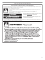
SÉCURITÉ DE LA SÉCHEUSE
Risque possible de décès ou de blessure grave si vous ne
suivez pas immédiatement les instructions.
Risque possible de décès ou de blessure grave si vous
ne suivez pas les instructions.
Tous les messages de sécurité vous diront quel est le danger potentiel et vous disent comment réduire le risque de blessure et
ce qui peut se produire en cas de non-respect des instructions.
Votre sécurité et celle des autres est très importante.
Nous donnons de nombreux messages de sécurité importants dans ce manuel et sur votre appareil ménager. Assurez-vous de
toujours lire tous les messages de sécurité et de vous y conformer.
AVERTISSEMENT
DANGER
Voici le symbole d’alerte de sécurité.
Ce symbole d’alerte de sécurité vous signale les dangers potentiels de décès et de blessures graves à vous
et à d’autres.
Tous les messages de sécurité suivront le symbole d’alerte de sécurité et le mot “DANGER” ou
“AVERTISSEMENT”. Ces mots signient :

18
AVERTISSEMENT : Pour votre sécurité, les renseignements dans ce manuel doivent
être observés pour réduire au minimum les risques d’incendie ou d’explosion ou pour
éviter des dommages au produit, des blessures ou un décès.
– Ne pas entreposer ou utiliser de l’essence ou d’autres vapeurs ou liquides
inflammablesàproximitéde cet appareil ou de tout autre appareil électroménager.
– QUE FAIRE DANS LE CAS D’UNE ODEUR DE GAZ :
•
Ne pas tenter d’allumer un appareil.
•
Ne pas toucher àun commutateur électrique; ne pas utiliser le téléphone se trouvant
sur les lieux.
•
Évacuer tous les gens de la pièce, de l’édifice ou du quartier.
•
Appeler immédiatement le fournisseur de gaz d’un téléphone voisin. Suivre ses
instructions.
•
À défaut de joindre votre fournisseur de gaz, appeler les pompiers.
– L’installation et l’entretien doivent être effectués par un installateur qualifié, une
agence de service ou le fournisseur de gaz.
AVERTISSEMENT : L’odorat ne permet pas toujours la détection d’une fuite de gaz.
Les distributeurs de gaz recommandent l’emploi d’un détecteur de gaz (homologation UL ou CSA).
Pour d’autre information, contacter le fournisseur de gaz local.
En cas de détection d’une fuite de gaz, exécuter les instructions “Que faire dans le cas d’une odeur de gaz”.
IMPORTANT : L'installation du gaz doit se conformer aux codes locaux, ou en l'absence de codes locaux, au code canadien
d'installation B149.1 du gaz naturel ou du propane.
La sécheuse doit être électriquement reliée à la terre conformément aux codes locaux, ou en l'absence de codes locaux, au Code
canadien de l'électricité, CSA C22.1.
Dans l’État du Massachusetts, les instructions d’installation suivantes sont applicables :
■ Les travaux d’installation et réparation doivent être exécutés par un plombier ou tuyauteur qualifié ou licencié, ou par le
personnel qualifié d’une entreprise licenciée par l’État du Massachusetts.
■ Si une vanne à boisseau sphérique est utilisée, elle doit comporter une manette “T”.
■ Si un conduit de raccordement flexible est utilisé, sa longueur ne doit pas dépasser 3 pi.

19
EXIGENCES D'INSTALLATION
Niveau
Mètre-ruban
Pince
Le sachet de pièces se trouve dans le tambour de la sécheuse.
Vérier que toutes les pièces sont présentes.
REMARQUE : À ne pas utiliser si la sécheuse doit être installée
sur un piédestal.
Consulter les codes locaux. Vérier l'alimentation électrique et
le circuit d'évacuation existants. Voir “Spécications électriques”
et “Exigences concernant l'évacuation” avant d'acheter les
pièces.
Vérier les exigences des codes. Certains codes limitent ou
n'autorisent pas l'installation des sécheuses dans un garage,
un placard, une maison mobile ou une chambre à coucher.
Contacter l'inspecteur en bâtiment local.
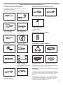
Tournevis à lame plate Tournevis Phillips n° 2
Clé à molette avec
ouverture jusqu'à
1" (25 mm) ou clé à
douille à tête hexagonale
Pince à dénuder les ls
(pour les installations
à raccordement direct)
Cisaille de ferblantier
(pour l'installation d'un
nouveau conduit)
Pistolet à calfeutrage et
composé de calfeutrage
(pour l'installation d'un nouveau
conduit d'évacuation)
Brides de serrage pour
conduit d'évacuation
Tourne-écrou de 1/4"
(recommandé)
Outils nécessaires aux installations au gaz :
Clé à tuyau de 8" ou 10"
Clé à molette de 8" ou 10" (pour
le raccordement au gaz)
Composé d'étanchéité
des raccords letés
– résistant au gaz
propane
Couteau utilitaire
Pièces fournies (tous les modèles)
Pieds de nivellement (4)
Connecteur en “Y” Tuyau d'alimentation
court
Tuyau d'alimentation
long
Rondelle de caoutchouc
Pièces fournies (modèles à vapeur) :
OUTILLAGE ET PIÈCES
Rassembler les outils et composants nécessaires avant
d'entreprendre l'installation.
Outils nécessaires pour toutes les installations :

20
Équipement facultatif : (Non fourni avec la sécheuse)
Se référer au Guide d'utilisation et d'entretien pour des
renseignements sur les accessoires disponibles pour la
sécheuse.
EXIGENCES D'EMPLACEMENT
Il vous faudra :
Un emplacement permettant une évacuation appropriée. ■
Voir “Exigences concernant l'évacuation”.
Si on utilise un cordon d'alimentation, une prise électrique ■
avec liaison à la terre située à moins de 2 pi (610 mm) de
l'un des côtés de la sécheuse. Voir “Spécications
électriques”.
Le plancher doit supporter le poids de la sécheuse de ■
200 lb (90,7 kg). Il faut également prendre en compte le
poids des appareils ménagers voisins.
Des robinets d'eau froide situés à 4 pi (1,2 m) maximum ■
des valves de remplissage, et une pression d'eau de 20 à
100 lb/po² (137,9 à 689,6 kPa). L'alimentation en eau de
la laveuse peut être utilisée avec le connecteur en “Y” et
le tuyau court (si nécessaire) fournis.
20 à 100 lb/po² (138 à 690 kPa) pour un rendement optimal. ■
Un plancher de niveau ayant une pente maximale de ■
1" (25 mm) sous l'ensemble de la sécheuse. Si la pente
est supérieure à 1" (25 mm), installer un ensemble de
pieds d'extension pour sécheuse, pièce n° 279810. Si
la sécheuse n'est pas d'aplomb, le linge peut ne pas
culbuter convenablement, et les programmes automatiques
commandés par détecteur peuvent ne pas fonctionner
correctement.
Pour l'installation dans un garage, placer la sécheuse ■
à au moins 18" (460 mm) au-dessus du sol. En cas
d'utilisation d'un piédestal, il faudra 18" (460 mm)
jusqu'au fond de la sécheuse.
Pour chaque aménagement, prévoir davantage d'espace pour
faciliter l'installation et l'entretien; des espacements pour les
appareils voisins, les murs, les portes et les plinthes. L'espace
doit être assez grand pour ouvrir complètement la porte. Ajouter
un espacement sur tous les côtés de la sécheuse pour réduire le
transfert du bruit. Si une porte de placard ou une porte à claire-
voie est installée, des ouvertures de ventilation en haut et en bas
sont nécessaires.
■
DIMENSIONS DE LA SÉCHEUSE
Vue de face :
27"
(686 mm)
3
/4"
(18 mm)
35
3
/8"
(899 mm)
Vue latérale :
3
1
/2"
(89 mm)
6
7
/8"
(175 mm)
29"
(736 mm)
Optional side
exhaust vent
location
Emplacement latéral
facultatif du conduit
d'évacuation
La page est en cours de chargement...
La page est en cours de chargement...
La page est en cours de chargement...
La page est en cours de chargement...
La page est en cours de chargement...
La page est en cours de chargement...
La page est en cours de chargement...
La page est en cours de chargement...
La page est en cours de chargement...
La page est en cours de chargement...
La page est en cours de chargement...
La page est en cours de chargement...
-
 1
1
-
 2
2
-
 3
3
-
 4
4
-
 5
5
-
 6
6
-
 7
7
-
 8
8
-
 9
9
-
 10
10
-
 11
11
-
 12
12
-
 13
13
-
 14
14
-
 15
15
-
 16
16
-
 17
17
-
 18
18
-
 19
19
-
 20
20
-
 21
21
-
 22
22
-
 23
23
-
 24
24
-
 25
25
-
 26
26
-
 27
27
-
 28
28
-
 29
29
-
 30
30
-
 31
31
-
 32
32


Maytag Duet Steam WGD9270X Installation Instructions Manual
- Catégorie
- Sèche-linge
- Taper
- Installation Instructions Manual
dans d''autres langues
- English: Maytag Duet Steam WGD9270X