Vulcan-Hart 137716-000BP Manuel utilisateur
- Catégorie
- Fours
- Taper
- Manuel utilisateur
Ce manuel convient également à

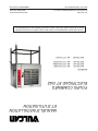
INSTALLATION &
OPERATION MANUAL
FORM 47110 (April 2014)
GAS & ELECTRIC
COMBI OVENS
MODELS
ABC7E-208 ML-137716-000BP
ABC7E-240 ML-137716-000BW
ABC7E-480 ML-137716-000CD
ABC7G-NAT ML-137715-NAT
For additional information on Vulcan-Hart or to locate an authorized parts
and service provider in your area, visit our website at www.vulcanequipment.com
VULCAN-HART
DIVISION OF ITW FOOD EQUIPMENT GROUP, LLC
WWW.VULCANEQUIPMENT.COM
3600 NORTH POINT BLVD.
BALTIMORE, MD 21222

IMPORTANT FOR YOUR SAFETY
THIS MANUAL HAS BEEN PREPARED FOR PERSONNEL QUALIFIED TO INSTALL GAS
EQUIPMENT, WHO SHOULD PERFORM THE INITIAL FIELD START-UP AND ADJUSTMENTS
OF THE EQUIPMENT COVERED BY THIS MANUAL.
POST IN A PROMINENT LOCATION THE INSTRUCTIONS TO BE FOLLOWED IN THE EVENT
THE SMELL OF GAS IS DETECTED. THIS INFORMATION CAN BE OBTAINED FROM THE
LOCAL GAS SUPPLIER.
IMPORTANT
IN THE EVENT A GAS ODOR IS DETECTED, SHUT DOWN UNITS
AT MAIN SHUTOFF VALVE AND CONTACT THE LOCAL GAS
COMPANY OR GAS SUPPLIER FOR SERVICE.
FOR YOUR SAFETY
DO NOT STORE OR USE GASOLINE OR OTHER FLAMMABLE
VAPORS OR LIQUIDS IN THE VICINITY OF THIS OR ANY OTHER
APPLIANCE.
IMPROPER INSTALLATION, ADJUSTMENT,
ALTERATION, SERVICE OR MAINTENANCE CAN CAUSE
PROPERTY DAMAGE, INJURY OR DEATH. READ THE
INSTALLATION, OPERATING AND MAINTENANCE INSTRUCTIONS
THOROUGHLY BEFORE INSTALLING OR SERVICING THIS
EQUIPMENT.
IN THE EVENT OF A POWER FAILURE, DO NOT ATTEMPT TO
OPERATE THIS DEVICE.
KEEP AREA AROUND OVEN CLEAR OF COMBUSTIBLES. DO
NOT OBSTRUCT COMBUSTION AND VENTILATION OPENINGS
ON THE OVEN.
RETAIN THIS INSTRUCTION MANUAL FOR FUTURE
REFERENCE
– 2 –
©VULCAN, 2014

– 3 –
TABLE OF CONTENTS
GENERAL ..............................................................................................................................................................4
INSTALLATION ......................................................................................................................................................4
Unpacking ........................................................................................................................................................4
Installation Codes and Standards ....................................................................................................................4
Location ...........................................................................................................................................................5
Door Opening ...................................................................................................................................................5
Stacking Kits ....................................................................................................................................................5
Leveling ............................................................................................................................................................5
Handling ...........................................................................................................................................................5
Water Requirements ........................................................................................................................................5
Water Quality Statement ..................................................................................................................................6
Water Conditioning ...........................................................................................................................................7
Plumbing Connections .....................................................................................................................................7
Water Supply Connections ...............................................................................................................................7
Filter System ....................................................................................................................................................8
Drain Connection .............................................................................................................................................8
Gas Supply Connections .................................................................................................................................8
Testing the Gas Supply System .......................................................................................................................9
Flue Gas Exhaust ............................................................................................................................................9
Electrical Connection .....................................................................................................................................10
Grounding ......................................................................................................................................................10
Vent Hood ......................................................................................................................................................10
Before First Use .............................................................................................................................................10
OPERATION .........................................................................................................................................................11
Controls ..........................................................................................................................................................11
Off/On.............................................................................................................................................................12
Temperature ...................................................................................................................................................12
Time ...............................................................................................................................................................13
Humidity .........................................................................................................................................................13
Daily Shutdown ..............................................................................................................................................14
Extended Shutdown .......................................................................................................................................14
Oven Drains ...................................................................................................................................................14
STAINLESS STEEL EQUIPMENT CARE AND CLEANING .................................................................................15
CLEANING ...........................................................................................................................................................16
Door Gasket ...................................................................................................................................................16
Oven Compartment ........................................................................................................................................17
Deliming the Cavity (Electric and Gas Units) .................................................................................................18
MAINTENANCE ...................................................................................................................................................19
Door Locking and Gasket Inspection .............................................................................................................19
Cooling Fans ..................................................................................................................................................19
Oven Light Replacement ...............................................................................................................................19
Alarms and Errors ..........................................................................................................................................19
Service and Parts Information ........................................................................................................................19

– 4 –
INSTALLATION, OPERATION AND CARE OF
ABC7 SERIES COMBI
SAVE THESE INSTRUCTIONS
GENERAL
Vulcan combination ovens are designed and assembled in the USA with quality workmanship and material.
Proper installation, usage and maintenance will result in many years of satisfactory performance. It is
suggested that you thoroughly read this entire manual and carefully follow all of the instructions provided.
The ABC Combi is unique in many ways but most notable is the controls: Temperature, Time, and Humidity.
The most essential, yet consistent control capability for a combi.
INSTALLATION
Before installing, verify that the electrical and/or gas supply agrees with the specifi cations on the data plate
located on the lower front corner of the right side panel. If the supply and equipment requirements do not
agree, do not proceed with the installation. Contact your dealer or Vulcan-Hart immediately.
UNPACKING
Each oven is inspected before leaving the factory. The transportation company assumes full responsibility
for safe delivery upon acceptance of the shipment. Immediately after delivery, unpack and check for
shipping damage. If the oven is damaged, save the packing material and contact the carrier immediately.
There is a fi fteen-day limitation on fi ling freight damage claims with the freight company. Freight damage
is not covered under warranty.
INSTALLATION CODES AND STANDARDS
In the United States, the Vulcan Combi Oven must be installed in accordance with:
1. State and local codes.
2. National Fuel Gas Code, ANSI-Z223.1 (latest edition). Copies may be obtained from The American
Gas Association, Inc.; 1515 Wilson Blvd.; Arlington, VA 22209.
3. National Electrical Code (ANSI/NFPA No.70, latest edition) available from the National Fire Protection
Association, Batterymarch Park, Quincy, MA 02269.
4. Vapor Removal from Cooking Equipment, (NFPA-96, latest edition) available from NFPA.
In Canada, the Vulcan Combi Oven must be installed in accordance with:
1. Local codes.
2. CAN/CGA-B149.1 Natural Gas Installation Code (latest edition).
3. CAN/CGA-B149.1 National Fuel Gas Code (latest edition), available from The Canadian Gas
Association; 178 Rexdale Blvd.; Etobicoke, Ontario; Canada M9W 1R3.
4. Canadian Electrical Code (CSA C22.2 No.3, latest edition) available from the Canadian Standards
Association, 5060 Spectrum Way, Mississauga, Ontario, Canada L4W 5N6.

– 5 –
LOCATION
Allow space for operating the oven. Do not obstruct the ventilation ports above the oven. To provide
ventilation access, allow 1" clearance on the left side of the oven and 3" clearance on the right and 4" at
the rear. A suitable amount of space (18" minimum) should be provided on the right side of the machine
for service. Ensure a level fl oor is available for operation.
DOOR OPENING
The oven is delivered with the door hinged on the left and cannot be reconfi gured.
STACKING KITS
Stacking kits are available to allow ovens to stack, one on top of the other. Assembly Instructions are
included with the kit.
LEVELING
Use a spirit level on a rack in the oven to make sure the oven is level, both front-to-back and side-to-side.
Adjustment of the leveling feet on the bottom of the legs can be made by turning the feet in or out to level
the oven. After the drain is connected, check for level by pouring water onto the fl oor of the oven cavity.
All water should drain through the drain opening. Adjust leveling if necessary.
HANDLING
Make sure that the lifting device used has a lifting capacity suitable for the weight
to be lifted and that it has been well maintained.
Perform the handling operations using a lifting device that is rated 20% higher than
the weight of the combi.
Do not stand or walk under the unit when lifting or handling it. Failure to observe
these instructions could cause serious injury.
Follow the instructions for lifting the combi included in the stand or stacking kit ordered with the unit.
WATER REQUIREMENTS
As with all steam related products, water fi ltration and regular fi lter replacements coupled with routine
deliming are required. Your local Vulcan Service offi ce can recommend a water treatment system to
meet the needs of your local water conditions. Contact your local Vulcan Service representative for water
treatment offerings.

– 6 –
WATER QUALITY STATEMENT
The fact that a water supply is potable is no guarantee that it is suitable for steam generation. Proper
water quality can improve the taste of the food prepared in the oven, reduce scale build-up or corrosion,
and extend equipment life. Local water conditions vary from one location to another and can change
throughout the year. The recommended water treatment for effective and effi cient use of this equipment
will vary depending on the local water conditions. Your water supply must be within the general guidelines
outlined in the chart below at all times during use of this machine or service issues not covered under
warranty may result.
Water hardness should be treated by removing the impurities (water softener with carbon block or de-
chlorinator and/or in-line water treatment). Low water hardness may also require a water treatment system
to reduce potential corrosion. Water treatment has been shown to reduce costs associated with machine
cleaning, reduce deliming and reduce corrosion of metallic surfaces.
Daily washing and rinsing of the cavity is required. In some cases it may be needed more than once a day
to prevent compounding of contaminants deposited inside cavity even with acceptable fi ltration. Failure
to wash and rinse down the cavity daily could result in damage of the oven cavity and interior parts. A
Reverse Osmosis water treatment system can be installed to eliminate chlorides or other contaminates
from the water if needed.
NOTE: Failure to properly maintain water quality or preventative procedures for water can lead to issues
not covered under warranty.
WATER SUPPLY GENERAL GUIDELINES*
Supply Pressure (dynamic fl ow) 30-60 psig
Hardness less than 3 grains (17.1 ppm = 1 grain of hardness)
Silica less than 13 ppm
Chloramines** zero
Chlorides** less than 30 ppm***
Total Chlorine**** zero
PH range 7-8
Un-Dissolved Solids less than 5 microns
* Testing of water is always done AFTER water fi lter or water treatment used. Water quality does change
with usage and should be checked after idle times to see if the condition worsens.
** A carbon block fi lter system should always be used to remove Chlorine and Chloramine. If a water
softener is used, a carbon block is still required. Check with your local water treatment specialist for proper
sizing and replacement intervals for the carbon block cartridge.
*** If the Chlorides exceed 30 ppm and the oven is used more than 8 hours during the day in steam or
combination mode the cavity will require rinsing every 8 hours. Failure to do so will result in corrosion and
rusting of the oven cavity and interior parts. A Reverse Osmosis water treatment system can be installed
to eliminate chlorides from the water and reduce the hardness. Preventative washing and rinsing may be
needed more than once a day to prevent compounding of contaminants inside cavity.
**** Total Chlorine of 4.0 ppm is the max limit for the building water supply. A carbon block fi lter must still
be used to remove all Chlorine and Chloramines from the water. Failure to do so will result in corrosion
and rust in the cooking cavity which is not covered under warranty.

– 7 –
WATER CONDITIONING
It is important to furnish the combi oven with treated water to reduce scale formation. Scale formation will
reduce steam output, cause premature component failure, and shorten equipment life. Most water supplies
contain scale producing minerals such as Calcium and Magnesium. As steam is generated, the minerals
are deposited into the oven cavity.
This may cause several problems:
1. Reduced heat transfer effi ciency.
2. Premature heating element failures.
3. Deposits inside the cavity that can lead to deterioration of the cavity and glass.
These problems are common to any manufacturer's steamer regardless of design, but they can all be
minimized by furnishing the combi oven with treated water and/or performing routine deliming and fi lter
maintenance.
The desired water properties can best be achieved by using a properly maintained water treatment system.
Strainers or fi lters will not remove minerals from the water.
Steamers that operate over a long period of time without the benefi t of a water treatment system develope
a heavy scale build up. These systems should be cleaned before using.
PLUMBING CONNECTIONS
Plumbing connections must comply with applicable sanitary, safety and
plumbing codes.
NOTE: Failure to properly connect the water lines will result in equipment failure that is not covered under
warranty.
WATER SUPPLY CONNECTIONS
There are two water connections for the combi. Treated water connection supplies steam creation and
spray hose water. Untreated water is only used for drain water tempering. Both connections must have
water supplied to them. If only treated water is available then make both connections with treated water.
Do not supply untreated water to treated connection as it will void warranty.
Connect the treated cold water supply line, min of 3/8" ID, to the ¾" garden hose inlet on the rear of the
Combi Oven. Connect the untreated cold water supply line to the ¾" garden hose, also on the rear of
the Combi Oven for drain water tempering. All water that enters into the oven cavity needs to be treated.
Tempering water is allowable to be untreated.
A water fi lter system is required for the water supply line going to the treated water inlet of your Combi
Oven. Follow the recommendations for use and installation instructions shipped with the water fi lter. If a
water fi lter is not installed, the Combi Oven warranty is limited.
NOTE: Failure to properly connect the water lines will result in equipment failure that is not covered under
warranty.

– 8 –
FILTER SYSTEM
In addition to water conditioning for the control of solids, you must have a carbon block fi lter installed
and maintained. Carbon block fi lters remove the chlorine and chloramines disinfectants from the water.
Chlorine/chloramines will erode the oven cavity, rack guides, racks, and internal components, which is not
covered under warranty. Check with your local water treatment specialist for proper sizing and replacement
intervals for the carbon block cartridge.
Water feed lines to the oven must be fl ushed before fi nal connection. Particles in the water could clog
tubing and components that supply water for steam production and drain cooling. If the water supply is not
free of sediment or cloudy after several minutes of fl ushing, a sediment fi lter must be installed before use.
If you have purchased a water fi lter system from Vulcan-Hart, please follow the instructions provided with
the fi lter system. At the time of installation you must register your Combi Oven at www.vulcanhart.com/
fi lterreg or use the reply card supplied with your unit. You will need to register your Combi Oven at each
fi lter change to insure your standard and extended warranty is maintained.
Filter purchase invoices and maintenance records must be provided with warranty claims.
DRAIN CONNECTION
In order to avoid any back pressure in the oven, do not connect solidly to any drain.
The 1" NPT threaded fi tting at the rear of the combi must be extended a minimum of 12" (305 mm) -
maximum of 72" (1829 mm) away from combi base, to an open air gap type drain. Do not reduce the
drain piping throughout its length. Provide a suitable fl oor sink with a minimum depth of 12" (305 mm).
The fl oor sink is NOT to be directly under the combi. The drain should slope down away from the combi
¼" for every foot of drain pipe length. The drain pipe should be either iron or copper. DO NOT use PVC
pipe; PVC pipe may lose its rigidity or glue may fail.
In order to avoid any back pressure in the oven, do not connect solidly to any drain connection.
GAS SUPPLY CONNECTIONS
Gas supply connections and any pipe joint compound must be resistant to the
action of propane gases.
A ¾" NPT minimum inside diameter gas supply line is required.
If quick disconnect devices are used, make sure it is sized
properly for data plate BTU/hr. rating.
Codes require that a manual gas shutoff valve be installed in
the gas line ahead of the combi oven. The gas line must be capable of delivering gas to the combi oven
without excessive pressure drop at the minimum rate specifi ed on the rating plate.
Inadequate gas supply could result in burner noise and poor burner performance.
The proper sizing and installation of the gas connection is important for the machine to operate within
its design specifi cations. In some installations, the gas supply may not be suffi cient enough to allow all
the gas equipment to operate properly at peak loads; or when other equipment with a high BTU/hr. input
requirement is operating. The connection to the machine becomes even more important in this type of
location. Flexible gas connectors with quick disconnect or swivel fi ttings (when used) and gas connectors
beyond the length necessary will reduce the BTU/hr. fl ow capacity to the machine.
NOTE: Do not use corrugated stainless steel tubing for commercial gas equipment supply connections.
MINIMUM RATE
Gas Input 3/4" NPT
Natural 5" - 14" W.C.
Propane 11" - 14" W.C.

– 9 –
NOTE: A straight gas connection is the ideal condition for the rated BTU/hr. fl ow capacity of the connector.
If a straight connection is not possible and a fl exible gas connector is used, do not twist, kink or excessively
fl ex the connector beyond a U-shape. Flexing the gas connector as described will restrict gas fl ow or may
damage the connector.
Changing a fl exible gas connector may raise the BTU/hr. fl ow capacity enough to allow the machine to
operate within its design specifi cations. (i.e. Removing the quick disconnect fi tting, installing a shorter gas
connector or installing a larger diameter gas connector.)
An alternative may be to move the equipment to a different gas supply location in the kitchen. (i.e. Closer
to the main supply into the kitchen or away from other equipment with high BTU/hr. input requirements.)
The combi oven is equipped with a factory preset pressure regulator. Natural gas pressure regulators are
preset for 5.0" W.C. (1.2 kPa). Propane gas pressure regulators are preset for 10.0" W.C. (2.46 kPa). No
further adjustment should be required. Check gas pressures with a manometer at time of installation to
verify that they agree with the pressures specifi ed.
Conversion Kit - GASKIT-ABC – Propane & altitude kit (2,000-10,000 ft.) are available and are to be fi eld
installed as needed.
Prior to lighting, check all joints in the gas supply line for leaks. Use soap and water
solution. Do not use an open fl ame. After piping has been checked for leaks, all piping receiving
gas should be fully purged to remove air.
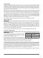
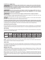
Model Volts Hertz Phase Amps (Max Used) BTU/Hr *Breaker (Amps)
ABC7G 120 60 1 5.0 80,000 15
* Breaker rating is based on electrical standard 125% increase over actual amps used.
TESTING THE GAS SUPPLY SYSTEM
When gas supply pressure exceeds
1
/2 psig (3.45 kPa), the oven and its individual shutoff valve must be
disconnected from the gas supply piping system.
When gas supply pressure is
1
/2 psig (3.45 kPa) or less, the oven should be isolated from the gas supply
system by closing its individual manual shutoff valve.
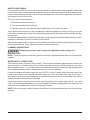
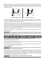
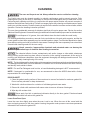
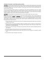
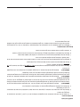
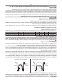
FLUE GAS EXHAUST
The fl ue is shipped loose and must be installed prior to operation. Failure to install
will cause service issues and will void warranty.
DO NOT obstruct the fl ow of fl ue gases from the fl ue located on the top of the combi oven. It is recommended
that the fl ue gases be vented to the outside of the building through a ventilation system installed by
qualifi ed personnel. Information on the construction and installation of ventilating hoods may be obtained
from Vapor Removal from Cooking Equipment, NFPA-96 (latest edition) available from the National Fire
Protection Association, Batterymarch Park, Quincy, MA 02269.
The output temperature of the exhaust fumes reach 480°F.
INCORRECT INSTALLATION CORRECT INSTALLATION
COMBI WALL COMBI WALL

– 10 –
ELECTRICAL CONNECTION
Appliances equipped with a fl exible electric supply cord are provided with a three-
prong grounding plug. It is imperative that this plug be connected into a properly grounded three-
prong receptacle. If the receptacle is not the proper grounding type, contact an electrician. Do not
remove the grounding prong from this plug.
Electrical and grounding connections must be in accordance with local codes, or
in the absence of local codes, with the National Electrical Code, ANSI/NFPA 70, or the Canadian
Electrical Code, CSA C22.2, as applicable.
Disconnect electrical power supply and follow lockout / tagout procedures.
The wiring diagram is located on the inside surface of the right side panel as you face the oven. Use
copper wire rated for at least 194°F (90°C) for the connection.
Do not drill a hole in the back panel for electrical connection. Use the strain relief locations
provided. This will allow proper access to components for service.
To make the electrical connections, remove the right side protective panel. Insert the power supply cable
through the strain relief at the rear of the unit. Once the optimal cable length is established for the connections
to the terminal board, clamp the cable using the strain relief. Connect the cables with the terminal board
as indicated on the wiring diagram. The wires on the terminal board must be clamped fi rmly.
Gas Model Electrical Connection
Not recommended for ground-fault circuit-interrupter (GFCI) 125-volt, single-phase, 15- and 20-ampere
receptacle. Electronic burner ignition systems are prone to nuisance tripping and possible ignition failure.
GROUNDING
The oven must be properly grounded. Connect the ground conductor to the terminal block in the position
indicated on the terminal block label.
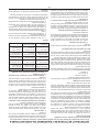
Model PH
208 V. 240 V. 480 V.
KW AMP KW AMP KW AMP
ABC7E
1 18 86.5 24 100 - -
3 18 50 24 57.8 24 28.9
* Breaker rating is based on electrical standard 125% increase over actual amps used.
NOTE: Single-phase blower motors are used on these ovens so there is no need to check direction of
motor rotation. The fan will rotate in the proper direction.
VENT HOOD
Local codes may require the oven to be located under an exhaust hood. Information on the construction
and installation of ventilating hoods may be obtained from Vapor Removal from Cooking Equipment, NFPA
Standard No. 96 (latest edition).
BEFORE FIRST USE
Calibration of the humidity measurement system must be performed prior to fi rst use. Refer to the
service instructions on how to perform this step prior to fi rst use. Altitude and gas supply affect humidity
measurement system so calibration is required before fi rst use.
Before using the oven for the fi rst time, it must be "burned in" to release any odors that might result from
heating the new surfaces in the oven. Remove any packaging material and instructions from inside and
outside of the unit as the surfaces will get hot. Operate the oven at maximum thermostat setting for 45
minutes.

– 11 –
OPERATION
The oven and its parts are hot. Use care when operating, cleaning or servicing the
oven. The cooking compartment contains live steam. Stay clear while opening the door.
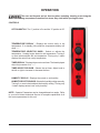
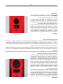
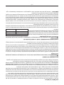
CONTROLS
OFF/ON SWITCH - The “I” position is On and the “O” position is Off.
TEMPERATURE DISPLAY - Displays the current cavity or set
temperature. If in standby (idle) mode the temperature display will
show “---”.
TEMPERATURE SELECTOR KNOB - Selects or adjusts the
temperature. Heating begins based on set temperature. Turning 2
or more indents adjusts the set temperature. Turning only 1 indent
displays the actual oven cavity temperature.
TIMER DISPLAY - Displays the current or set timer. The time displayed
when fi rst powered on is “--:--”.
TIMER SELECTOR KNOB - Selects the set timer. Adjust knob to
the left or right to increase or decrease the time.
HUMIDITY DISPLAY - Displays the current or set humidity.
HUMIDITY SELECTOR KNOB - Selects the humidity setting manually.
Turning 2 or more indents adjusts the humidity setting. Turning only
1 indent displays actual oven cavity humidity.
NOTE: Operator Parameters can be changed based on needs. Refer
to your local Vulcan Authorized Service for complete capabilities of all
the custom parameters for this unit.

– 12 –
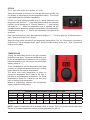
OFF/ON
The “I” side of the switch is On and the “O” is Off.
When the unit switch is turned on ,for both gas and electric models, the
unit powers up and displays the last temperature setting. The unit will
begin heating and fan operation immediately.
If there is no recall settings possible (due to a power disconnect), the
temperature will default to “---” which deactivates heating, fan and water
injection, but all displays are lit. Time will default to “--:--” and humidity
will default to “---”. When the temperature knob is adjusted, the unit
operates based on parameter settings for temperature, time ,and humidity.
If temperature display is “---”, there is still functionality in the timer knob
as a timer.
Door lights will remain on when the temperature display is “---”. The door lights are off when the door is
open – and on when the door is closed.
When the off/on switch is turned off, the temperature display blinks “CLn” for 3 seconds as a reminder to
clean the unit. The time display shows “good”, and the humidity display shows “bye”. After 3 seconds all
displays will be blank.
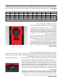
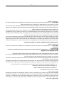
TEMPERATURE
Turning the temperature knob to the right increases
temperature set point. Turning the temperature knob
to the left decreases the temperature until it reaches
lowest temperature. One more turn to the left displays
standby mode as “---”.
To set a temperature, turn the temperature knob past
2 indents to a desired temperature and stop. Heating
begins based on this new set temperature.
The actual oven cavity temperature is shown by
turning the temperature dial 1 indent to the right or
left when a set temperature is displayed. The actual
temperature is shown for 3 seconds, and then goes
back to displaying set temperature.
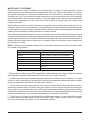
Making a temperature selection will automatically
select a default humidity setting.
TEMPERATURE AND HUMIDITY DEFAULT SETTINGS
Temperature 80-99 100-109 110-119 120-129 130-149 150-169 170-179 180-189 190-259
Humidity 90 80 70 60 50 60 70 80 100
Temperature 260-269 270-279 280-289 290-299 300-319 320-349 350-379 480-409 410-449 450
Humidity 90 80 70 60 50 40 30 20 10 0
NOTE: Operator Parameters can be changed based on needs. Refer to your local Vulcan Authorized
Service for complete capabilities of all the custom parameters for this unit.

– 13 –
TIME
Time is displayed in “hours & minutes”. When the unit
is fi rst powered on, the time display shows “--:--”. To
increase time, turn knob to the right, and to decrease
time, turn knob to the left. When the knob stops, the
displayed time countdown then begins.
When the time counts down to "00:00", the display will
fl ash and the operator will be alerted with a buzzer and
lights (based on parameter settings). To add time, turn
the knob to the right to the desired additional time. The
buzzer stops when additional time is added. To mute
the buzzer function, turn the knob to the left with the
door shut. The display lights will still fl ash. Opening
the door stops the time and the buzzer. Shutting the
door will reset the time function to the last time setting.
When the door is opened during an active countdown time, the time pauses and restarts when the door
is shut.
At the end of a time cycle “00:00” fl ashes. If no adjustment of the time knob is made and “00:00” is still
displayed when the door is shut, the last time setting is automatically recalled and the time countdown
starts again.
To manually return to a no time setting, turn the timer knob to the left until --:-- is displayed. The time
function does not control or affect the heating or humidity functions.
Setting time works the same when the door is either open or closed. Time does not count down when
the door is open.
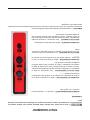
HUMIDITY
The humidity set point has an automatic setting based
on temperature selection. The operator can increase
or decrease the humidity setting manually by turning
the knob more than 1 indent to the left to decrease or
more than 1 indent to the right to increase. Turning only
1 indent displays actual oven cavity humidity.
Recall of the last humidity setting also occurs when the
temperature is switched off and then back on. Default
settings are used unless a manual humidity setting
adjustment is made.
NOTE: When checking actual humidity the display may
show " - " while the sensor is initializing.

– 14 –
DAILY SHUTDOWN
1. Place the Selector Knob to 0 (OFF).
2. Clean the oven interior (See Cleaning).
3. Leave door open.
EXTENDED SHUTDOWN
1. Perform DAILY SHUTDOWN procedure.
2. Turn off the circuit breakers and/or gas supply.
3. Turn off the water supply.
4. Leave door open.
5. Check water fi ltration upon returning to use.
OVEN DRAINS
Keep the oven drain free of blockage:
1. Inspect the oven drain daily for any blockage.
2. Remove any particles or debris from the perforated strainer daily (more often if needed).
3. Avoid large debris from entering drain by always leaving screen cover on.

– 15 –
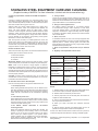
STAINLESS STEEL EQUIPMENT CARE AND CLEANING
(Supplied courtesy of NAFEM. For more information, visit their web site at www.nafem.org)
Contrary to popular belief, stainless steels ARE susceptible to
rusting.
Corrosion on metals is everywhere. It is recognized quickly on iron
and steel as unsightly yellow/orange rust. Such metals are called
“active” because they actively corrode in a natural environment when
their atoms combine with oxygen to form rust.
Stainless steels are passive metals because they contain other
metals, like chromium, nickel and manganese that stabilize the
atoms. 400 series stainless steels are called ferritic, contain
chromium, and are magnetic; 300 series stainless steels are called
austenitic, contain chromium and nickel; and 200 series stainless,
also austenitic, contains manganese, nitrogen and carbon. Austenitic
types of stainless are not magnetic, and generally provide greater
resistance to corrosion than ferritic types.
With 12-30 percent chromium, an invisible passive fi lm covers the
steel’s surface acting as a shield against corrosion. As long as the
fi lm is intact and not broken or contaminated, the metal is passive
and stain-less. If the passive fi lm of stainless steel has been broken,
equipment starts to corrode. At its end, it rusts.
Enemies of Stainless Steel
There are three basic things which can break down stainless steel’s
passivity layer and allow corrosion to occur.
1. Mechanical abrasion
2. Deposits and water
3. Chlorides
Mechanical abrasion means those things that will scratch a steel
surface. Steel pads, wire brushes and scrapers are prime examples.
Water comes out of the faucet in varying degrees of hardness.
Depending on what part of the country you live in, you may have hard
or soft water. Hard water may leave spots, and when heated leave
deposits behind that if left to sit, will break down the passive layer and
rust stainless steel. Other deposits from food preparation and service
must be properly removed.
Chlorides are found nearly everywhere. They are in water, food
and table salt. One of the worst chloride perpetrators can come from
household and industrial cleaners.
So what does all this mean? Don’t Despair!
Here are a few steps that can help prevent stainless steel rust.
1. Use the proper tools.
When cleaning stainless steel products, use non-abrasive tools.
Soft cloths and plastic scouring pads will not harm steel’s passive
layer. Stainless steel pads also can be used but the scrubbing
motion must be in the direction of the manufacturers’ polishing
marks.
2. Clean with the polish lines.
Some stainless steel comes with visible polishing lines or “grain.”
When visible lines are present, always scrub in a motion parallel
to the lines. When the grain cannot be seen, play it safe and use
a soft cloth or plastic scouring pad.
3. Use alkaline, alkaline chlorinated or non-chloride
containing cleaners.
While many traditional cleaners are loaded with chlorides, the
industry is providing an ever-increasing choice of non-chloride
cleaners. If you are not sure of chloride content in the cleaner
used, contact your cleaner supplier. If your present cleaner
contains chlorides, ask your supplier if they have an alternative.
Avoid cleaners containing quaternary salts; it also can attack
stainless steel and cause pitting and rusting.
4. Treat your water.
Though this is not always practical, softening hard water can do
much to reduce deposits. There are certain fi lters that can be
installed to remove distasteful and corrosive elements. To insure
proper water treatment, call a treatment specialist.
5. Keep your food equipment clean.
Use alkaline, alkaline chlorinated or non-chloride cleaners
at recommended strength. Clean frequently to avoid build-
up of hard, stubborn stains. If you boil water in stainless steel
equipment, remember the single most likely cause of damage
is chlorides in the water. Heating cleaners that contain chlorides
have a similar effect.
6. Rinse, rinse, rinse.
If chlorinated cleaners are used, rinse and wipe equipment and
supplies dry immediately. The sooner you wipe off standing water,
especially when it contains cleaning agents, the better. After
wiping equipment down, allow it to air dry; oxygen helps maintain
the stainless steel’s passivity fi lm.
7. Never use hydrochloric acid (muriatic acid) on stainless
steel.
8. Regularly restore/passivate stainless steel.
Job Cleaning Agent Comments
Routine cleaning Soap, ammonia,
detergent, Medallion
Apply with soft
cloth or sponge.
Fingerprints
and smears
Arcal 20, Lac-O-
Nu Ecoshine
Provides barrier fi lm
Stubborn stains
and discoloration
Cameo, Talc, Zud,
First Impression
Rub in direction
of polish lines.
Grease and fatty
acids, blood,
burnt-on foods
Easy-off, DeGrease
It Oven Aid
Excellent removal
on all fi nishes
Grease and Oil Any good
commercial
detergent
Apply with soft
cloth or sponge.
Restoration/
Passivation
Benefi t, Super
Sheen
Review
1. Stainless steels rust when passivity (fi lm-shield) breaks down
as a result of scrapes, scratches, deposits and chlorides.
2. Stainless steel rust starts with pits and cracks.
3. Use the proper tools. Do not use steel pads, wire brushes or
scrapers to clean stainless steel.
4. Use non-chlorinated cleaners at recommended concentrations.
Use only chloride free cleaners.
5. Soften your water. Use fi lters and softeners whenever
possible.
6. Wipe off cleaning agent(s) and standing water as soon as
possible. Prolonged contact causes eventual problems.
To learn more about chloride-stress corrosion and how to prevent it,
contact the equipment manufacturer or cleaning materials supplier.
Developed by Packer Engineering, Naperville, Ill., an independent
testing laboratory.

– 16 –
CLEANING
The oven and its parts are hot. Always allow the oven to cool before cleaning.
The Combi oven must be cleaned regularly to maintain performance and to prevent corrosion. Daily
cleaning and rinsing of the cavity is necessary to remove the contaminants found in water and in food.
Performing daily cleaning and rinsing in conjunction with proper water fi ltration will prevent corrosion of
stainless steel and lime scale build-up. Failure to manage proper daily cleaning and maintenance of water
quality can void the warranty. Periodic cleaning is required to the exterior to ensure continued safe, reliable
operation. Review the cleaning instruction provided.
The oven has considerable amounts of stainless steel that will require proper care. Review the section
Stainless Steel Equipment Care and Cleaning for additional information about proper care for stainless steel.
Do not dispose of oil, grease, fat or solid debris down the drain inside the combi cavity.
For cleaning and delime procedures, removal of wire rack shelves, side rack guide supports, and the fan
screen guard to clean them separately may be needed based on usage. Food residue deposited on these
items during cooking can build up in hard to clean areas. Cleaning these items separately can extend their
life and lower cleaning needs for the oven cavity.
Harsh, corrosive, inappropriate chemicals and untreated water can destroy the
protective passivation layer of stainless steel leading to corrosion.
The chemical effects of water contaminants, salt and/or vinegar or other acidic substances
during cooking could create long-term effects of corrosion in the cooking compartment. At the end of a
cooking cycle with these substances, clean the equipment thoroughly with detergent and rinse well. This
is in addition to daily cleaning/rinsing of the cavity.
NOTE: The liquid detergent for cleaning the cooking compartment must have certain chemical characteristics.
The detergent should have a pH level between 8-12 and be free of chlorine/ammonia and have viscosity
and density levels similar to water.
NOTE: Pot and Pan Detergent used in sinks, or hand dishwashing detergent is NOT recommended.
NOTE: If detergent is questionable for use, we recommend to share the MSDS sheet with a Vulcan
representative for review/approval.
DOOR GASKET
1. Clean the gasket-sealing surface of the oven doors to remove food acids for maximum gasket life.
Do not use any solvents or sharp instruments.
2. Wash with a cloth moistened in a solution of mild detergent and warm water.
3. Rinse with a fresh cloth moistened with warm water to remove all traces of detergent.
4. Wipe dry with a clean cloth.
Never apply food oils or petroleum lubricants directly to the door gasket. Petroleum-based
solvents and lubricants will reduce the gasket life.
Leave Oven Door Open
Leave the oven door slightly open when the oven is not in use. When the oven is idle, never latch the
door and apply pressure to the door gasket. Leaving the gasket under pressure can cause permanent
deformation and reduce the gasket life.

– 17 –
OVEN COMPARTMENT
Daily
1. The oven cavity should be cooled below 140°F before beginning routine cleaning.
2. Remove any large pieces of food that may be in the oven cavity before starting a cleaning cycle.
3. Spray the inside of the oven compartment with approved detergent solution.
NOTE: Use a mild oven detergent for cleaning. Commercial cleaners such as Ecolab
®
“Specialty
Oven Cleaner” or other common oven degreasers can be used. Do not use abrasive cleaners. Be
sure to read and follow the instructions of the detergent ensuring thorough rinsing after use.
NOTE: Do not use cleaners containing grit, abrasive materials, bleach, harsh chemicals, acidic
based detergents, chlorides (ammonia) or chlorinated cleaners. Never use hydrochloric acid (muriatic
acid) on stainless steel.
NOTE: Do not use steel wool or abrasive pad on stainless steel or glass surfaces.
4. Close the combi oven door and set temperature to 190°F and set timer for 10 minutes (humidity
defaults to 100%).
5. Rinse entire cavity thoroughly with spray hose.
6. Clean door gasket & glass with cloth moistened in solution of mild soap and warm water. Do not use
abrasive pad on glass.
7. Rinse door gasket & glass with fresh cloth moistened with warm water.
8. Clear drain cover screen inside cavity of any debris and rinse cavity again.
9. Leave the door open overnight to vent cavity.
Weekly Cleaning
1. Clean any air vents and cooling fans on the exterior of the oven. Dust can collect on the vent openings.
Clogged vents can cause oven components to overheat.

– 18 –
DELIMING THE CAVITY (ELECTRIC AND GAS UNITS)
As with all steam related products, water fi ltration and regular fi lter replacements coupled with
routine deliming are required. Your local Vulcan Service offi ce can recommend a water treatment system
to meet the needs of your local water conditions. Contact your local Vulcan Service representative for
water treatment offerings.
Oven cavity deliming should be done on a regular basis. The frequency depends on oven use, quality
of the local water supply and what type of water treatment system is used. Even with the use of a water
treatment system, periodic deliming of the oven cavity is still required. If lime scale build up becomes
visibly noticeable, then the oven cavity deliming should be performed.
Deliming should only be performed on a cool oven after a clean cycle has occurred.
NOTE: All components inside the oven cavity, such as the heating elements, racks, and rack guides can
be sprayed with white vinegar or a deliming product. It is not recommended to spray interior glass with
deliming product and immediate rinsing with water at least 3 times is suggested should it come in contact
with the glass. Deliming solution may cause the surface of glass to etch which leads to a cloudy look on
the glass that cannot be removed.
1. Remove wire racks, rack guides and fan guard for separate deliming following the same procedures
as below for the cavity.
2. Spray the entire oven cavity with white vinegar (full strength) and let it stand for no longer than 15
minutes. Or use a deliming product. When using a deliming product other than white vinegar, follow
the directions on the product label.
3. Rinse entire cavity thoroughly with spray hose ensuring a deep rinse where all deliming chemical
was sprayed.
4. Rinse door gasket & glass with fresh cloth moistened with warm water.
5. Install fan guard, rack guides and wire racks after delime and rinse process is completed for those
parts.
6. Leave the door open overnight to vent cavity.

– 19 –
MAINTENANCE
Disconnect the electrical power to the machine and follow lockout / tagout procedures.
DOOR LOCKING AND GASKET INSPECTION
During oven operation, if air or steam blows out from the top, sides, or underneath to door, the door may
need adjustment. Inspect the door locking movement and the door gasket for issues.
Door Locking Inspection
When closing door, the locking action should be smooth with no binding and not require excessive force.
The door must exert enough pressure on the gasket to prevent steam from exiting the oven cavity. If the
door locking is extremely tight, contact your local Vulcan Authorized Service for any repairs or adjustments
needed on this equipment.
Door Gasket Inspection
Visually inspect the door gasket for cracks, splits, and missing sections.
Using a dollar bill or a strip of plain paper approximately the same size, position the paper between door
and gasket then close the door. The paper should fi t tightly and not be easily removed when pulled. Check
tightness near the corners and in the center locations at the left, top and right sides of door. If the door
gasket is not sealing properly, contact your local Vulcan Authorized Service for any repairs or adjustments
needed on this equipment.
Door Gasket Replacement
Contact your local Vulcan Authorized Service to replace the gasket.
COOLING FANS
Each combi has multiple cooling fans used to circulate air through the controls and components area.
Routine monthly inspection of each cooling fan vent is recommended. Make sure each cooling fan is
operating and free of obstruction, dust and debris.
OVEN LIGHT REPLACEMENT
Do not touch new bulb glass with bare hand.
1. Open hinged inner glass door.
2. Remove the glass lens cover. Carefully remove the lens avoid damaging the lens.
3. Remove and replace the defective light bulb.
4. Reinstall the lens cover making sure the gasket is properly seated.
ALARMS AND ERRORS
Any "E#" on display indicates an error has occurred. Refer to service manual or contact Vulcan Authorized
Service.
When applicable, the Control Panel display may show the following alarms:
1. Temperature Display “Err” - Shutdown required, toggle off/on switch to reset.
2. Time Display "No Heat" - check gas supply connection, toggle off/on switch to reset.
3. Humidity Display “Err” – humidity sense error. A small dot in the upper left corner is also visible of
the humidity display.
SERVICE AND PARTS INFORMATION
Contact your authorized service offi ce for any repairs or adjustments needed on this equipment.

– 20 –
NOTES
FORM 47110 (April 2014) PRINTED IN U.S.A.
La page est en cours de chargement...
La page est en cours de chargement...
La page est en cours de chargement...
La page est en cours de chargement...
La page est en cours de chargement...
La page est en cours de chargement...
La page est en cours de chargement...
La page est en cours de chargement...
La page est en cours de chargement...
La page est en cours de chargement...
La page est en cours de chargement...
La page est en cours de chargement...
La page est en cours de chargement...
La page est en cours de chargement...
La page est en cours de chargement...
La page est en cours de chargement...
La page est en cours de chargement...
La page est en cours de chargement...
La page est en cours de chargement...
La page est en cours de chargement...
-
 1
1
-
 2
2
-
 3
3
-
 4
4
-
 5
5
-
 6
6
-
 7
7
-
 8
8
-
 9
9
-
 10
10
-
 11
11
-
 12
12
-
 13
13
-
 14
14
-
 15
15
-
 16
16
-
 17
17
-
 18
18
-
 19
19
-
 20
20
-
 21
21
-
 22
22
-
 23
23
-
 24
24
-
 25
25
-
 26
26
-
 27
27
-
 28
28
-
 29
29
-
 30
30
-
 31
31
-
 32
32
-
 33
33
-
 34
34
-
 35
35
-
 36
36
-
 37
37
-
 38
38
-
 39
39
-
 40
40


Vulcan-Hart 137716-000BP Manuel utilisateur
- Catégorie
- Fours
- Taper
- Manuel utilisateur
- Ce manuel convient également à
dans d''autres langues
- English: Vulcan-Hart 137716-000BP User manual
Documents connexes
Autres documents
-
Vulcan ABC7G Stacked Le manuel du propriétaire
-
Vulcan C24GA10 PS Le manuel du propriétaire
-
-
Vulcan C24GA Steamer Le manuel du propriétaire
-
Blodgett BCX -14G Mode d'emploi
-
Blodgett BLCM-102G Mode d'emploi
-
Blodgett BLCP-202G Mode d'emploi
-
-
-
Blodgett BCM-102 Mode d'emploi