Bosch HBL87M53UC Guide d'installation
- Catégorie
- Micro-ondes
- Taper
- Guide d'installation
Ce manuel convient également à

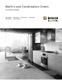
Installation Manual
Built-in and Combination Ovens
HBL8463UC HBL8443UC HBL8743UC HBL8453UC
HBL8753UC HBL87M53UC

2
Table of Contents
Installation instructi ons
9 Safety Definitions ..................................................... 3
IMPORTANT SAFETY INSTRUCTIONS ........................ 4
Appliance Handling Safety ................................................. 4
Safety Codes and Standards ............................................. 4
Electric Safety ....................................................................... 4
Related Equipment Safety .................................................. 4
Proposition 65 Warning ...................................................... 4
Transport ................................................................................ 5
Bosch Combination Ovens ........................................... 6
Before you Begin ........................................................... 6
Tools and Parts Needed ..................................................... 6
Parts Included ....................................................................... 6
Power Requirements and Grounding ............................... 6
For Best Installation ............................................................. 6
Checklist ................................................................................ 6
Removing Packaging .................................................... 7
Built-in Ovens: ....................................................................... 7
Combination Ovens: ............................................................ 7
Packaging Bracket Removal-Left and Right Sides ........ 7
Preparing Ovens ................................................................... 7
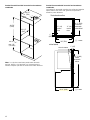
Appliance and Cabinet Cutout Dimensions ............... 8
Dimensions for Single Oven Units .................................... 8
Dimensions for Combination Oven Units ........................ 9
Electrical Installation - Grounding Instructions ....... 11
Electrical Connection ....................................................... 11
Four-wire Connection ....................................................... 11
Three-wire Connection ..................................................... 11
Oven Installation ......................................................... 12
For Best Installation .......................................................... 12
Pre-Assembly of the Combination Oven ...................... 12
Remove Oven Door Prior to Installation ....................... 14
Installing the Oven into the Cabinet .............................. 15
How to Replace the Oven Door ..................................... 16
Testing Operation .............................................................. 17
Bosch
®
Support ........................................................... 17
Before Calling Service ..................................................... 17
Rating Label ....................................................................... 17
Service ................................................................................ 17
Parts and Accessories ..................................................... 17
4XHVWLRQV"
ZZZERVFKKRPHFRPXV
:HORRNIRUZDUGWRKHDULQJIURP\RX
7KLV%RVFK$SSOLDQFHLVPDGHE\
%6++RPH$SSOLDQFHV&RUSRUDWLRQ
0DLQ6WUHHW6XLWH
,UYLQH&$

3
9 Safety Definitions
Safety Defi nitions
9 WARNING
This indicates that death or serious injuries may
occur as a result of non-observance of this warning.
9 CAUTION
This indicates that minor or moderate injuries may
occur as a result of non-observance of this warning.
NOTICE: This indicates that damage to the appliance or
property may occur as a result of non-compliance with
this advisory.
Note: This alerts you to important information and/or
tips.

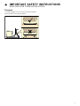
9 IMPORTANT SAFETY INSTRUCTIONS
READ AND SAVE THESE INSTRUCTIONS
4
IMPORTANT SAFET Y I NS T RU CT I ONS RE AD AND SAVE THESE INSTRUCTIONS
IMPORTANT: SAVE THESE INSTRUCTIONS FOR THE
LOCAL ELECTRICAL INSPECTOR’S USE.
INSTALLER: LEAVE THESE INSTALLATION
INSTRUCTIONS WITH THE UNIT FOR THE OWNER.
OWNER: PLEASE RETAIN THESE INSTRUCTIONS FOR
FUTURE REFERENCE.
WARNING
If the information in this manual is not followed exactly,
fire or shock may result causing property damage or
personal injury.
WARNING
Do not repair, replace or remove any part of the
appliance unless specifically recommended in the
manuals. Improper installation, service or maintenance
can cause injury or property damage. Refer to this
manual for guidance. All other servicing should be done
by an authorized servicer.
Appliance Handling Safety
CAUTION
Safety Codes and Standards
This appliance complies with the latest version of one or
more of the following standards:
▯ CAN/CSA C22.2 No. 61 - Household Cooking Ranges
▯ UL 858 - Household Electric Ranges
▯ CAN/CSA C22.2 No. 150 - Microwave Ovens
▯ UL 923 - Microwave Cooking Appliances
▯ CSA C22.2 No. 64 - Household Cooking and Liquid-
Heating Appliances
▯ UL 1026 - Electric Household Cooking and Food
Serving Appliances
It is the responsibility of the owner and the installer to
determine if additional requirements and/or standards
apply to specific installations.
Electric Safety
Before you plug in an electrical cord, be sure all controls
are in the OFF position.
If required by the National Electrical Code (or Canadian
Electrical Code), this appliance must be installed on a
separate branch circuit.
Installer - show the owner the location of the circuit
breaker or fuse. Mark it for easy reference.
Important - save these instructions for the local electrical
inspector’s use.
Before installing, turn power OFF at the service panel.
Lock service panel to prevent power from being turned
ON accidentally.
Refer to rating label for more information. See “Rating
Label” under “Service” for rating label location.
Be sure your appliance is properly installed and
grounded by a qualified technician. Installation, electrical
connections and grounding must comply with all
applicable codes.
Related Equipment Safety
Remove all tape and packaging before using the
appliance. Destroy the packaging after unpacking the
appliance. Never allow children to play with packaging
material
Never modify or alter the construction of the appliance.
For example, do not remove leveling legs, panels, wire
covers or anti-tip brackets/screws.
Before starting up the appliance, remove any packaging
material and adhesive film from the cooking
compartment and the door.
Proposition 65 Warning:
This product may contain a chemical known to the State
of California, which can cause cancer or reproductive
harm. Therefore, the packaging of your product may
bear the following label as required by California:
▯ Unit is heavy and requires at least two people
or proper equipment to move.
▯ For double and triple ovens three or more
people are needed to assist with lifting the unit
into place.
▯ Do not lift appliance by door handle.
▯ Hidden surfaces may have sharp edges. Use
caution when reaching behind or under
appliance.
&DQFHUDQG5HSURGXFWLYH+DUPZZZ3:DUQLQJVFDJRY
67$7(2)&$/,)251,$352326,7,21:$51,1*
:$51,1*

5
9 IMPORTANT SAFETY INSTRUCTIONS
READ AND SAVE THESE INSTRUCTIONS
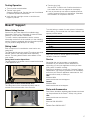
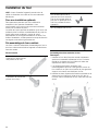
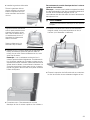
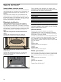
Transport
To avoid damage to the oven vent, use the transport
method shown in the picture below.

6
Bosch Combination Ovens
The HBL8743UC, HBL8753UC and HBL87M53UC Bosch
combination ovens are sold as sets, each of which
includes two built-in oven components: a conventional
wall oven (lower oven) and either a built-in speed oven or
a microwave oven(upper oven).
▯ For ease of installation and improved alignment, the
oven components are assembled together in the
customer’s home rather than at the factory.
▯ Each of the components are packed in separate
boxes, which are strapped together prior to shipping.
▯ The combination ovens listed here are approved for
use in a single cutout, using single power connection.
▯ Each conventional oven component is designed with
an oven-mounted junction box on top, which is used
for connecting the upper oven power cable.
▯ The hardware required for mounting the speed oven
on top of the conventional oven will be found inside
the conventional oven box.
▯ Each of the oven components has its own rating label,
the component model number, FD number, etc.
Before you Begin
Tools and Parts Needed
▯ Phillips-head screwdriver
▯ Star-head screwdriver (T20)
▯ Measuring tape
▯ Drill with bit (1/8”)
▯ Gloves
▯ Utility Knife
Parts Included
Phillips head screws (6).
Power Requirements and Grounding
The outlet must be properly grounded in accordance with
all applicable codes.
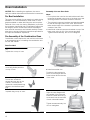
For Best Installation
The oven can be difficult for two people to handle during
installation. It is recommended that three or more people
be available to assist with lifting the unit into place.
Removal of the oven door (to reduce the unit weight and
to provide necessary gripping points) can be
cumbersome unless the detailed door removal
instructions are followed carefully. Do not attempt to
remove the speed oven door.
Please take time to read and follow the instructions
provided for an improved installation experience.
Checklist
Use this checklist to verify that you have completed each
step of the installation process. This can help you avoid
mistakes.
▯ Before installing the oven, be sure to verify the cabinet
dimensions are correct and the required electrical
connections are present.
▯ Refer to additional information in this manual
regarding Safety, Cabinet Dimensions, Removing
Packaging, Electrical Installation, Testing the
Installation and Customer Service.
▯ Remove the lower oven door to reduce the unit weight
and to provide access to gripping points for lifting. See
“Remove Lower Oven Door Prior to Installation”
information.
▯ Move the oven units into place in front of the cabinet
opening, leaving the bottom packaging on the units to
avoid damaging flooring.
▯ Remove the Star-head screws (T-20 size using Star-
head screwdriver) holding the speed microwave oven
to the base of its carton.
▯ Assemble the two units of the combination oven. See
“Pre-Assembly of the Combination Oven”.
▯ Connect the power cable from the lower oven to the
junction box in the cabinet.
▯ Remove the Star-head screws (T-20 size using Star-
head screwdriver) holding the lower oven to the base
of its carton.
▯ Team-lift the unit directly into the cabinet cutout taking
care not to pinch fingers, scratch arms or hands.
▯ Slide the unit all the way into place.
▯ Fasten the unit to the cabinet opening with the screws
supplied using a Philips screwdriver.
▯ Reinstall the oven door removed in Step 3 above.
▯ Consult the complete installation instructions and
follow the remainder of the procedures listed,
including performing operation test.
▯ INSTALLER- Leave the literature pack and the
accessories with the customer.

7
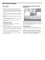
Removing Packaging
Built-in Ovens:
1.
Cut the straps.
2.
Open top of carton and remove top wood frame.
3.
Lift the carton up and over the appliance to remove, or
carefully cut along the cut line on the back left side of
the carton with a blade shorter than 3/4” and remove
carton.
4.
Carefully remove internal protective packaging taking
care to secure any loose accessories and instruction
manuals.
5.
Remove bracket(s) securing appliance to base pad, if
present.
6.
The unit should stay on the packaging base until ready
to be lifted into cabinet cutout.
7.
Install the appliance according to the installation
instructions.
Combination Ovens:
1.
Cut the straps and remove angle board/strap
protectors from top of carton.
2.
Open top of carton.
3.
Lift the carton up and over the appliance to remove, or
carefully cut along the cut line on the back left side of
the carton with a blade shorter than 3/4” and remove
carton.
4.
Carefully remove the microwave or steam oven carton
from top of bottom carton and place on floor.
5.
Follow instructions on interior cartons for removal of
remaining packaging.
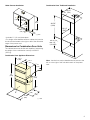
Packaging Bracket Removal-Left and
Right Sides
Note: Actual bracket varies in appearance. The bracket
remains in the packaging base. The unit should stay on
the packaging base until ready to be lifted into cabinet
cutout or onto the lower oven.
Preparing Ovens
Place ovens in front of the cabinet where it is to be
installed so that they are in line with the cabinet cutout.
Check to be sure all packing materials have been
removed from the unit. Also remove the accessories,
oven racks, literature pack and any shipping materials
from inside the oven cavity. Check both ovens for a
double oven or combination oven installation.

8
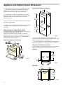
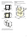
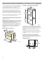
Appliance and Cabinet Cutout Dimensions
It is good practice, when an oven is installed at the end
of a cabinet run, adjacent to a perpendicular wall, or
cabinet door, to allow at least 1/4” (6.4 mm) space
between the side of the oven and the wall/door.
For oven support, install 2x4s extending front to back
flush with the bottom and the sides of the opening. The
supporting base must be well secured to the floor/
cabinet and level.
Junction boxes can be located anywhere within reach of
the oven’s power cable.
The cabinet base must be flat and capable of supporting
the weight of the combination oven up to 429 lbs.
(195 kg).
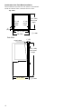
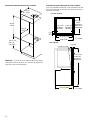
Dimensions for Single Oven Units
The cabinet base must be flat and capable of supporting
a weight of at least 232 lbs (105 kg).
Under oven dimensions are provided as a general
guideline and may be adjusted as needed based on a
particular application. Consult a design professional for
optimizing personal preferences.
Single Oven Appliance Dimensions
Single Oven Wall Mount Installation
*For single ovens installed into a wall cabinet, the
junction box may be located above, beneath, left or right
of the unit within reach of the power cord.
**For oven installation in a wall cabinet, the control panel
overlap is a minimum
3
/
8
" (10mm) to max. 2" (51mm).
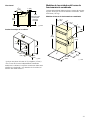
Single Oven Flush Mount Installation
Flush installation requires two side cleats to be attached
inside the cabinet frame, recessed from the front.
Top View
Side View
PP
PP
ʌ¼ʚ
PLQë
PD[
ò
IOXVKLQVHW
GHSWK
ò
ô
UHYHDO
FOHDWV
ô
UHYHDO
FOHDWV
PP
ò
ǫ
ǩ
IOXVK
FXWRXW
KHLJKW
PP
UHYHDO
FOHDWV

9
Under-Counter Installation
* Includes ¾” (19 mm) base plate.
**For single ovens installed under a cabinet, the junction
box should be located to the right or left of the unit within
range of the power cord.
Dimensions for Combination Oven Units
The cabinet base must be flat and capable of supporting
the weight of the combination oven up to 429 lbs
(195 kg).
Combination Oven Appliance Dimensions
Combination Oven Traditional Installation
Note: Junction box may be installed above, below, to the
left or to the right of the unit within reach of the power
cord.
ë
é
ê
ê
PP
PP
ë
ç¼ʚ
ʎ¼ʓʘ
ʌ¼ʚ
ç¼ʚ
ê
ê
PLQ
PD[

10
Combination Oven Flush Mount Installation
Flush installation requires two side cleats to be attached
inside the cabinet frame, recessed from the front.
7
RS
9L
HZ
PP
ë
UHYHDO
FOHDWV
ë
UHYHDO
FOHDWV
ê
IOXVKLQVHW
GHSWK
ê
UHYHDOFOHDWV
PP
6LGH9LHZ
ê
è¼ʚ
IOXVKFXWRXW
KHLJKW

11
Electrical Installation - Grounding Instructions
The assembled combination oven should be moved in
front of the cabinet opening and the power cable from
the lower oven should be connected to the cabinet
junction box.
All model ovens on the front cover of this installation
instruction manual are dual rated, designed to be
connected to either 208 or 240V AC, 60 Hz, 4 wire,
single-phase power supply.
The electrical supply should be a 4-wire single phase AC.
Install a suitable conduit box (not furnished). An
appropriately-sized, UL-listed conduit connector must be
used to correctly attach the conduit to the junction box.
Note: Local codes may vary. Installation, electrical
connections and grounding must comply with all
applicable local codes.
If local codes permit grounding through the electrical
supply neutral, connect both the white neutral wire and
the green ground wire from the oven to the white neutral
eletrical supply wire.
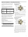
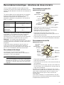
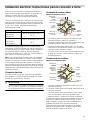
Electrical Connection
The four-wire connection is preferred, but where local
codes permit, the three wire connection is also
acceptable.
9 WARNING
When connected to a 4 or 5-wire, 120/208-Volt 3-
phase power supply, the phase C conductor is not
required for the operation of the appliance.
Four-wire Connection
Ungrounded Neutral
▯ Connect the red oven wire to the red electrical supply
wire (hot wire).
▯ Connect the black oven wire to the black electrical
supply wire (hot wire).
▯ Connect the white neutral oven wire to the white
neutral (not bare or green ground) electrical supply
wire.
▯ Connect the green ground oven wire to the bare or
green ground electrical supply wire.
Three-wire Connection
Grounded Neutral
▯ Connect red wire from oven to red wire in junction box.
▯ Connect black wire from oven to black wire in junction
box.
▯ Connect both green ground wire and white wire from
oven to white, green or bare neutral wire in junction
box.
The conduit cable, where connected at the oven, swivels.
Rotate conduit cable upward (or downward) and direct
through hole prepared in cabinet to attach to junction
box.
To maintain serviceability, the flex conduit must not be
shortened and should be routed to permit temporary
removal of the oven.
Model Circuit Required
HBL8463UC
HBL8443UC
HBL8453UC
208V, 60 Hz/ 240V, 60 Hz
30 AMP
HBL8743UC
HBL8753UC
HBL87M53UC
208V, 60 Hz/ 240V, 60 Hz
40 AMP
SRZHUVXSSO\
MXQFWLRQER[
UHGZLUHV
JUHHQRUEDUH
JUHHQZLUH
8/OLVWHG
FDEOHIURP
ZKLWHZLUHV
EODFNZLUHV
ZLUH
FRQQHFWRU
RYHQ
SRZHUVXSSO\
MXQFWLRQER[
UHGZLUHV
ZKLWHEDUHRU
ZKLWHZLUH
JUHHQZLUH
JUHHQZLUH
FDEOHIURP
8/OLVWHG
EODFNZLUHV
RYHQ
FRQQHFWRU

12
Oven Installation
NOTICE: Before installing the appliance, be sure to
verify the cabinet dimensions and electrical connections.
For Best Installation
The oven can be difficult for two people to handle during
installation. It is recommended to have three or more
people available to assist with lifting the unit into place.
Removal of the oven door during installation (to provide
the necessary handholds and to significantly reduce the
unit weight) can be cumbersome unless the detailed
door removal instructions are followed carefully. Please
take time to read and follow the instructions provided for
an improved installation experience.
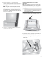
Pre-Assembly of the Combination Oven
Combination ovens require the oven and the microwave
to be assembled prior to installing the combination unit
into the wall cabinet.
Parts Provided
Assembly of the two Oven Units
Notes
▯ Do not place the oven into the wall cabinet until after
mounting the speed oven on top of the lower oven and
securing it with the universal connector brackets.
▯ The universal connector brackets are interchangeable
for the left and right sides of the oven. Be sure the
taller vertical edge of the bracket is positioned to the
outside of the oven.
1.
Install both universal connector brackets on top of the
lower oven using six (6) of the screws provided.
Tighten screws securely, but do not overtighten.
2.
Install decorative trim.
Universal connector bracket
(2):
in parts box on top of oven
Screws (16):
in red bag inside parts box
on top of oven.
Oven Mounting Screws (8):
Screws are included to
secure the oven trim to the
cabinet. The screws are
located in a small plastic bag
affixed to the literature pack
bag.
Trim Piece:
in plastic bag on top of oven.
Position the decorative trim
piece so the flanges with the
holes in them face to the rear
of the oven.
Align the outer flanges with
the outside of the universal
brackets. Fasten with one (1)
screw each into the end hole
of each universal bracket.
Tighten screws securely, but
do not overtighten.

13
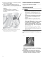
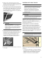
3.
Place the speed oven on top of the universal
connector brackets and fasten in place using three (3)
screws per side. Tighten the screw securely, but do
not overtighten.
Note: The existing screws in the speed oven base
help with alignment. When lowering the speed oven
into place on the universal connector brackets, allow
these screw heads to slide into the slots as shown in
the illustration below. The screw nearest the front of
the speed oven should slide into the base of the slope
at the front of the bracket.
4.
Continue to “Connecting the Speed Oven Electrical
Conduit to the Lower Oven”.
Connecting Speed Oven Electrical Conduit to
Lower Oven
Note: When installing the combination unit, the power
cable must be properly attached to the oven-mounted
junction box. This must be done prior to supplying
electrical power to the oven unit.
9 WARNING
Check to be sure that no electrical power has yet
been supplied to the oven.
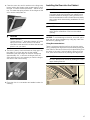
1.
Remove the oven-mounted junction box cover located
on the top rear of the oven. (See image below).
2.
Remove the cap from the conduit access hole in the
side of the oven-mounted junction box.
3.
Guide the wires from the conduit cable coming from
the speed oven through the hole in the oven-mounted
junction box. There are four wires coming from the
speed oven.

14
4.
Snap the conduit connector into the hole by pressing it
in until it clicks into place.
5.
Follow the wiring diagram label and match and
connect each wire by color to the wires attached to the
wiring block inside the oven-mounted junction box.
Push the bare end of the wire until it is snug in the
wiring block then tighten down the retaining screw on
each wire.
Tighten securely, but do not overtighten.
See previous illustration in Step 3 for finished
appearance.
6.
Replace the oven-mounted junction box cover and
tighten the two screws holding it in place.
Tighten securely, but do not overtignten.
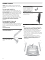
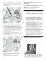
Remove Oven Door Prior to Installation
It is recommended to remove the conventional (lower)
oven door to help reduce the unit weight.
NOTICE: Do not remove the speed oven door.
How to Remove the Oven Door
9 WARNING
▯ Make sure oven is cool and power to the oven
has been turned off before removing the door.
Failure to do so could result in electrical shock or
burns.
▯ The oven door is heavy and parts of it are fragile.
Use both hands to remove the oven door. The
door front is glass. Handle carefully to avoid
breakage.
▯ Grasp only the side of the oven door. Do not
grasp the handle as it may swing in your hand
and cause damage or injury.
▯ Failure to grasp the oven door firmly and properly
could result in personal injury or product damage.
▯ To avoid injury from hinge bracket snapping
closed, be sure both levers are securely in place
before removing the door. Also, do not force door
open or closed-the hinge could be damaged and
injury could result.
▯ Do not lay removed door on sharp or pointed
objects as this could break the glass. Lay on a
flat, smooth surface, positioned so that the door
cannot fall over.
To help avoid injury or damage, be sure to read the
above WARNING before attempting to remove the oven
door.
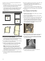
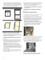
1.
Open the oven door to its fully open position.
2.
Flip levers on hinges toward you.
Note: It may be necessary to use a tool, such as a
screwdriver, to gently pry the upper part of the lever
away from the housing. Take care to avoid scratching
the housing.
3.
Bring both door hinge levers to their fullest down
position as shown in the illustration. The left and right
door hinges differ slightly but operate in the same
manner.

15
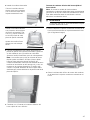
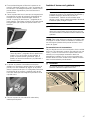
4.
Close the oven door until it catches on the hinge stop
levers, locking the hinges at the proper angle for door
removal. The door will be open about 7 inches at the
top. This takes the spring tension off the hinges so the
door can be easily lifted out.
9 CAUTION
PINCH HAZARD
Closing the door 7” takes the pressure off of the
spring. If this isn’t done, the door can still be
removed but the latch will now slam shut and will
pinch or cut your hand.
5.
The door is heavy. Use both hands to firmly grip it by
the sides. Do not grip the door by the handle.
Maintaining the door angle, lift the door straight up
approximately 3/4” to unhook the hinges from the
slots and then pull it out towards you until the hinges
are clear of the oven housing.
6.
Place the door in a convenient and stable location for
cleaning.
Installing the Oven into the Cabinet
9 CAUTION
It is recommended to wear gloves and long sleeves
to protect hands and forearms from abrasion and
potential scratches during the lifting process. It is
also recommended to take off watches and jewelry
and to wear work shoes during installation for foot
protection.
9 CAUTION
Three people or proper equipment are needed to
safely lift the combination oven into the cabinet
opening.
NOTICE: To avoid damage to the door, do not lift, pull or
push the unit during installation by using any oven door
handle as a gripping point.
Lifting Recommendations
There is a ridge across the top front of the oven cavity.
Lift by grasping this ridge with one hand while placing the
other hand on the back of the unit (for helpers lifting from
the sides of the unit). If a third helper is lifting from the
front, both hands should lift by holding this ridge area.
9 CAUTION
DO NOT attempt to lift the unit by holding the oven’s
upper heating element.

16
Proceed to lift the oven following the guidelines below
with the door removed:
▯ Lift points (1) on the front of the unit are for lifting from
the sides of the unit. Lift point (3) on the front of the
unit is for a third person to help lift the unit.
▯ Lift point (2) on the back of the unit shows the location
of the opposite hand for the helpers lifting from the
sides of the unit. Adjust the location as needed to
facilitate the lift.
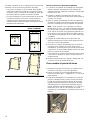
Placing Oven Into Cabinet Opening
1.
The unit and its bottom packaging (pallet) should be
positioned close to and in front of the cabinet opening
prior to beginning to lift the unit into place.
2.
Lift or slide unit into the cabinet cutout without allowing
the unit base to contact the flooring.
3.
Guide the unit straight back into the cabinet cutout.
Push the unit straight in until the oven trim is about
2 inches from being flush with cabinet wall.
Note: Be careful not to crimp the flexible conduit
between the oven and the cabinet back wall. If
necessary, guide the flexible conduit into the wall of
cabinet access hole so it doesn’t prevent the unit from
being pushed all the way into the cabinet opening. The
oven should be straight and level.
4.
Push the unit all the way back into the cabinet cutout
until the front edge of the unit is flush with the front of
the cabinet.
5.
Install the supplied screws through the tap holes in the
trim (2 screws for single ovens, 4 screws for
combination ovens). It is recommended to drill pilot
holes for the trim screws.
To ensure the door and oven function properly, the
screws should be installed on the face of the side trim
6.
Replace the oven door accordingly. See “Re-Install the
Oven Door”.
How to Replace the Oven Door
1.
Holding the door firmly in both hands, grip it on either
side, not by the handle.
2.
Tilt the door back slightly towards you until it opens
about 7 inches at the top.
3.
Slide the hinges into the slots as far as they will go and
then lower the door straight down. The angle of the
door may need to be adjusted slightly to allow the
hinges to engage properly and the door to lower into
place. The door should lower about 3/4” and stop. If
not, the hinges have not engaged properly and the
door could fall if it is released.
4.
Once both hinges are fully engaged as described in
Step 3, gently open the door until it is fully open.
5.
Push the levers on both the hinges up and forward
until they are locked into the slot and flush with the
front of the oven body.
6.
Close and open the door slowly to be sure it is
correctly and securely in place.
Single Oven Combination Oven
"
#

17
Testing Operation
1.
Turn on power at the breaker.
2.
Test the oven mode.
Select the BAKE mode. See the Use and Care Manual
for detailed operation instructions.
3.
Verify that the oven light comes on and the oven
begins to preheat.
4.
Test the door lock.
Set the SELF CLEAN mode. Confirm that the door
locks when the lock icon appears in the display.
5.
If any of the tests do not result as explained above,
contact Customer Service for assistance. Otherwise,
the installation is complete at this time.
Bosch
®
Support
Before Calling Service
See the Use and Care Manual for troubleshooting
information. Refer to the “Statement of Limited Product
Warranty” in the Use and Care Manual.
To reach a service representative, see the contact
information at the front of the manual or in the following
section. Please be prepared with the information printed
on your product rating label prior to calling.
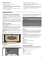
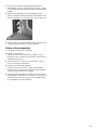
Rating Label
Each component of a combination oven has its own
rating label.
The rating label shows the model, FD number and serial
number. Refer to the rating label when requesting
service. The rating label location varies based on the
oven model.
Rating Label Location Speed Oven
The rating label of the speed oven is located at the inside
of the appliance door.
Rating Label Location Conventional Oven
The rating label of the conventional (lower) oven is
located at the left hand side of the door trim.
To avoid having to search for each piece of information
when calling, you can enter the four items needed in the
spaces provided below.
Keep your invoice or escrow papers for warranty
validation if service is needed.
Service
We realize that you have made a considerable
investment in your kitchen. We are dedicated to
supporting you and your appliance so that you have
many years of creative cooking.
Please don’t hesitate to contact our Customer Support
Department if you have any questions or in the unlikely
event that your Bosch® appliance needs service. Our
service team is ready to assist you.
USA
800-944-2904
www.bosch-home.com/us/support
Canada
800-944-2904
www.bosch-home.ca/en/support
Parts and Accessories
Parts, filters, descalers, stainless steel cleaners and more
can be purchased in the Bosch
®
eShop or by phone.
USA
www.bosch-home.com/us/store
Canada
Marcone 800-482-6022
or
Reliable Parts 800-941-9217
Conventional Oven
Model No.
FD-No.
Speed Oven
Model No.
FD-No.
Date of Purchase
Customer Service
O

18
Table des matières
Noti ce de montage
9 Définitions de sécurité ........................................... 19
IMPORTANTES CONSIGNES DE SÉCURITÉ ............. 20
Sécurité de manutention des appareils ........................ 20
Codes et normes de sécurité ......................................... 20
Sécurité électrique ............................................................ 20
Sécurité apparentée concernant l´équipement .......... 21
Avertissement issu de la proposition 65 ...................... 21
Transport ............................................................................. 21
Fours combinés Bosch ............................................... 22
Avant de commencer .................................................. 22
Outils et pièces nécessaires ........................................... 22
Pièces comprises .............................................................. 22
Exigences électriques et mise à la terre ...................... 22
Pour de meilleurs résultats d'installation ...................... 22
Liste de vérification ........................................................... 22
Retrait de l’emballage ................................................. 23
Fours intégrés : .................................................................. 23
Fours combinés : ............................................................... 23
Retrait des brides d'emballage – côtés gauche
et droit ................................................................................. 23
Préparation des fours ....................................................... 23
Dimensions de l'appareil et de la découpe des
armoires ....................................................................... 24
Dimensions pour les fours simples ............................... 24
Dimensions des modules de fours combinés ............. 25
Raccordement électrique : directives de mise
à la terre ....................................................................... 27
Raccordement électrique ................................................ 27
Raccordement à quatre fils ............................................. 27
Raccordement à trois fils ................................................ 27
Installation du four ...................................................... 28
Pour une installation optimale ........................................ 28
Pré-assemblage de four combiné ................................. 28
Retrait de la porte du four avant installation ................ 30
Installation du four dans l'armoire ................................. 31
Remontage de la porte du four ...................................... 32
Opération d’essai .............................................................. 33
Soutien Bosch
®
........................................................... 33
Avant d’appeler le service de réparations ................... 33
Plaque signalétique .......................................................... 33
Service ................................................................................ 33
Pièces et accessoires ..................................................... 33
9RXVDYH]GHVTXHVWLRQV"
ZZZERVFKKRPHFRPXV
ââ
1RXVQRXVIHURQVXQSODLVLUGHYRXVVHUYLU
&HWDSSDUHLOpOHFWURPpQDJHU%RVFKHVWIDEULTXpSDU
%6++RPH$SSOLDQFHV&RUSRUDWLRQ
0DLQ6WUHHW6XLWH
,UYLQH&$

19
9 Définitions de sécurité
Défi nitions de sécurité
9 AVERTISSEMENT
Ceci indique que le non-respect de cet
avertissement peut entraîner des blessures graves,
voire la mort.
9 ATTENTION
Ceci indique que le non-respect de cet
avertissement peut entraîner des blessures légères
ou de gravité moyenne.
AVIS : Ceci indique que la non-conformité à cet avis de
sécurité peut entraîner des dégâts matériels ou
endommager l'appareil.
Remarque : Ceci vous signale des informations et/ou
indications importantes.

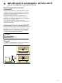
9 IMPORTANTES CONSIGNES DE SÉCURITÉ
LIRE ET CONSERVER CES INSTRUCTIONS
20
IMPORTANTES CONSI GNES DE SÉCURI T ÉLI RE ET CONSE RV E R CE S INSTRUCTIONS
IMPORTANT : CONSERVEZ CES CONSIGNES À
L'INTENTION DE L'INSPECTEUR EN ÉLECTRICITÉ.
INSTALLATEUR : PRIÈRE DE LAISSER CES
INSTRUCTIONS D'INSTALLATION AVEC CET APPAREIL
À L'INTENTION DU PROPRIÉTAIRE.
PROPRIÉTAIRE : PRIÈRE DE CONSERVER CES
INSTRUCTIONS POUR POUVOIR VOUS Y RÉFÉRER
ULTÉRIEUREMENT.
AVERTISSEMENT
Si l’information de ce guide n’est pas suivie exactement,
il peut en résulter un incendie ou un choc électrique
causant des dommages à la propriété, des blessures ou
la mort.
AVERTISSEMENT
Ne réparez, remplacez, ni ne retirez aucune partie de
l'appareil, excepté si les manuels recommandent de le
faire. Une installation, un entretien ou une inspection
incorrects peuvent occasionner des blessures ou des
dommages matériels. Reportez-vous au présent manuel
pour obtenir des indications. Toute autre intervention doit
être effectuée par un technicien agréé.
Sécurité de manutention des appareils
ATTENTION
Codes et normes de sécurité
Cet appareil est conforme aux plus récentes versions de
l'une ou plus des normes suivantes :
▯ CAN/CSA C22.2 No. 61 - Cuisinières pour usage
ménager (Household Cooking Ranges)
▯ UL 858 - Cuisinières électriques domestiques
(Household Electric Ranges)
▯ CAN/CSA C22.2 No. 150 - Fours à micro-ondes
(Microwave Ovens)
▯ UL 923 - Appareils de cuisson à micro-ondes
(Microwave Cooking Appliances)
▯ CSA C22.2 No. 64 - Appareils de cuisson domestique
et de chauffage des liquides (Household Cooking and
Liquid-Heating Appliances)
▯ UL 1026 - Appareils électriques domestiques pour la
cuisson et la préparation des aliments (Electric
Household Cooking and Food Serving Appliances)
Il incombe au propriétaire et à l'installateur de déterminer
si des exigences et/ou normes additionnelles
s'appliquent pour des installations spécifiques.
Sécurité électrique
Avant de brancher le cordon électrique, vérifier que
toutes les commandes sont à la position OFF (Arrêt).
S’il y a lieu, conformément au Code national de
l’électricité (ou au Code canadien de l’électricité), cet
appareil doit être installé sur un circuit de dérivation
séparé.
Installateur : indiquez au propriétaire l’emplacement du
disjoncteur ou du fusible. Identifiez sa position pour
pouvoir le retrouver facilement.
Important : Conservez ces consignes à l’intention de
l’inspecteur local en électricité.
Avant l'installation, coupez l'alimentation au panneau de
service. Verrouillez le panneau de service pour
empêcher que l'alimentation ne soit rétablie par accident.
Consultez la plaque signalétique pour de plus amples
renseignements. Consultez la section « Plaque
signalétique » dans « Réparation » pour l'emplacement
de la plaque signalétique.
Assurez-vous que l’appareil est correctement installé et
mis à la terre par un technicien qualifié. L’installation, les
raccordements électriques et la mise à la terre doivent
être conformes avec tous les codes en vigueur.
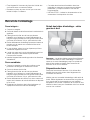
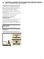
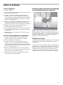
▯ L’appareil est lourd et son déplacement exige
au moins deux personnes ou encore un
équipement approprié.
▯ Il est recommandé de faire intervenir trois
personnes ou plus pour aider à soulever les
fours doubles ou triples afin de les mettre en
place.
▯ Ne pas soulever l'appareil électroménager par
la poignée de porte.
▯ Les surfaces cachées peuvent comporter des
arêtes vives. Redoubler de vigilance quand
vous passez la main derrière ou sous l'appareil
électroménager.
La page est en cours de chargement...
La page est en cours de chargement...
La page est en cours de chargement...
La page est en cours de chargement...
La page est en cours de chargement...
La page est en cours de chargement...
La page est en cours de chargement...
La page est en cours de chargement...
La page est en cours de chargement...
La page est en cours de chargement...
La page est en cours de chargement...
La page est en cours de chargement...
La page est en cours de chargement...
La page est en cours de chargement...
La page est en cours de chargement...
La page est en cours de chargement...
La page est en cours de chargement...
La page est en cours de chargement...
La page est en cours de chargement...
La page est en cours de chargement...
La page est en cours de chargement...
La page est en cours de chargement...
La page est en cours de chargement...
La page est en cours de chargement...
La page est en cours de chargement...
La page est en cours de chargement...
La page est en cours de chargement...
La page est en cours de chargement...
La page est en cours de chargement...
La page est en cours de chargement...
La page est en cours de chargement...
La page est en cours de chargement...
-
 1
1
-
 2
2
-
 3
3
-
 4
4
-
 5
5
-
 6
6
-
 7
7
-
 8
8
-
 9
9
-
 10
10
-
 11
11
-
 12
12
-
 13
13
-
 14
14
-
 15
15
-
 16
16
-
 17
17
-
 18
18
-
 19
19
-
 20
20
-
 21
21
-
 22
22
-
 23
23
-
 24
24
-
 25
25
-
 26
26
-
 27
27
-
 28
28
-
 29
29
-
 30
30
-
 31
31
-
 32
32
-
 33
33
-
 34
34
-
 35
35
-
 36
36
-
 37
37
-
 38
38
-
 39
39
-
 40
40
-
 41
41
-
 42
42
-
 43
43
-
 44
44
-
 45
45
-
 46
46
-
 47
47
-
 48
48
-
 49
49
-
 50
50
-
 51
51
-
 52
52


Bosch HBL87M53UC Guide d'installation
- Catégorie
- Micro-ondes
- Taper
- Guide d'installation
- Ce manuel convient également à
dans d''autres langues
- English: Bosch HBL87M53UC Installation guide
- español: Bosch HBL87M53UC Guía de instalación