
Over-the-Ra nge Microwave
In stallation Instructions
For Models: HMV9302. HMV9303. HMV9305, HMV9306, HMV9307
PLEASE READ ENTIRE INSTRUCTIONS BEFORE PROCEEDING
MPORTANT: Save these instructions for the local electrical inspector's use.
INSTALLER: Please leave these Installation nstructions with this unit for the owner.
OWNER: Please retain these instructions for future reference.
Printed in Korea
P/No.: 3828W5U0503

YOUR SAFETY FIRST
BEFORE YOU START
° Proper installation is the installer's responsibility!
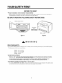
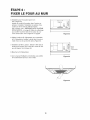
- Read the entire manual before you begin. The Model number label is located on the oven front. See Figure 1.
Mounting plate is located on back side of microwave oven. See Figure 2.
BE SURE TO READ THE FOLLOWING SAFETY INSTRUCTIONS:
Model Number Label
Mounting J
plate
( Remove from
oven to install.
.....
000000000%0000
Figure 1 Figure 2
WARNING
FOR YOUR SAFETY:
° You will need TWO people to install this oven. It is heavy and could cause personal injury if not handled properly.
The dimensions of the oven are as follows:
Height :16 7/16 inches
Width : 29 15/16inches
Depth : 15 5/8 inches
Weight : 60 Ibs.
• Avoid Electrical Shock!
- Before you drill into the wall, note where electrical outlets are and where electrical wires might be concealed
behind the wall. YOU COULD GET AN ELECTRIC SHOCK if you contact electrical wires with your drill bit.
- Locate and disconnect the power to any electrical circuits that could be affected by installing this oven.
IF YOU DO NOT DISCONNECT THE POWER, YOU COULD GET AN ELECTRIC SHOCK.
• ELECTRICAL RATING OF THIS OVEN : 120V AC 60Hz.
-You need a DEDICATED 120V, 60Hz, AC only, 15 or 20A, fused electrical supply (located in the cabinet above
the microwave as close as possible to the microwave) serving only the microwave.

YOUR SAFETY FIRST
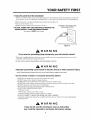
• THIS APPLIANCE MUST BE GROUNDED!
- If there is an electrical short circuit, grounding reduces the risk of electrical shock by providing an escape wire
for the electric current. This appliance is equipped with a cord having a grounding wire with a grounding plug.
• Place the plug into a properly installed and grounded outlet. See Figure 3.
• Do not use an extension cord.
• Keep the power cord dry and do not pinch or crush it.
• DO NOT, UNDER ANY CIRCUMSTANCES, REMOVE THE
POWER SUPPLY CORD GROUNDING PRONG!
This appliance MUST be grounded!
PROPERLY POLARIZED AND
GROUNDED OUTLET
Three-Pronged (Grounding) Plug
Figure 3
WARNING
If you use the grounding plug improperly, you risk electric shockZ
- Check with a qualified electrician if you are not sure whether the oven is properly grounded or if you do not
completely understand the grounding instructions.
DO NOT USE A FUSE IN THE NEUTRAL OR GROUNDING CIRCUIT.
WARNING
Improper grounding could result in electric shock or other personal injury.
SAVE THESE INSTRUCTIONS FOR THE LOCAL ELECTRICAL INSPECTOR'S USE.
• DO NOT EXPOSE YOURSELF TO EXCESSIVE MICROWAVE ENERGY!
- DO NOT try to operate the microwave oven with the door open.
- DO NOT tamper with or defeat the safety interlocks.
- DO NOT place objects between the microwave oven front face and the door.
- DO NOT allow soil or cleaner residue to build up on the flat surfaces around the microwave oven door.
- DO NOT operate the microwave oven if it is damaged.
- The microwave oven door must close properly to operate safely.
- DO NOT USE THE MICROWAVE OVEN:
• If the door is bent.
• If the hinges or latches are broken or loose.
• If the door sealing surfaces or glass is broken or cracked.
- DO NOT ATTEMPT TO ADJUST OR REPAIR THE OVEN YOURSELF!
It should be adjusted and repaired by a qualified technician who can check for microwave leakage after
repairing the oven.
WARNING
If you do not use the microwave oven as instructed,
you could be exposed to excessive microwave energy.

YOUR SAFETY FIRST
= MAKE SURE YOU HAVE ENOUGH SPACE AND SUPPORT.
- Mount the oven against a flat, vertical wall, so it is supported by the wall. The wall should be constructed of
minimum 2" x 4" wood studding and 3/8" thick drywall or plaster/lath.
- ATTACH AT LEAST ONE of the two lag screws supporting the oven to a vertical, 2" x 4" wall stud.
- DO NOT mount the microwave oven to an island or peninsula cabinet.
- BE SURE the upper cabinet and rear wall structures are able to support 150 Ibs., plus the weight of any items
you place inside the oven or upper cabinet.
- Locate the oven away from strong draft areas, such as windows, doors, and strong heating vents.
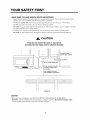
- BE SURE you have enough space. See Figure 4 below for minimum vertical and horizontal clearance.
CAUTION
If you do not mount the oven as instructed,
you risk personal injury and/or property damage.
Grounded Outlet
C_ (inside upper cabinet)
Power Supply Cord Hole
30"rain.cabinetopeningwidth
30" min. clearancefrom bottom
ofcabinetto cookingsurface
or countertop
(Use templates included
with installation instructions)
Figure 4
CAUTION
° Before you begin installing the oven, PLACE A PIECE OF THE CARTON OR OTHER HEAVY
MATERIAL (such as a blanket) over the countertop or cooktop to protect it. Do not use a plastic cover.
Failure to protect these surfaces could result in property damage.

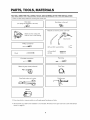
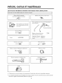
PARTS, TOOLS, MATERIALS
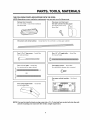
THE FOLLOWING PARTS ARE SUPPLIED WITH THE OVEN:
NOTE: Depending on your ventilation requirements, you may not use all of these parts.
Damper/duct connector
(for roof vented or wall vented installation)
Not Actual Size
One power cord clamp and
One dark-colored mounting screw
(to hold the power cord)
Actual Size
One power cord clamp bushing - Actual Size (for the cord hole in a metal upper cabinet)
Four 1/4" x 2" lag screws - Actual Size
(for wall stud holes)
Four 1/4" x 3" toggle bolts - Actual Size
(for drywall holes)
Two 1/4" x 3" bolts - Actual Size
OR
Four spring toggle heads -
(for the toggle bolts)
Actual Size
Two tapping screws - Actual Size
(for attaching the damper duct connector)
One upper cabinet template - Not Actual
Size
NOTE: You need to install at least one lag screw into a 2" x 4" stud and four anchor bolts into the wall,
and the mounting area must meet the 150 Ibs. weight requirement.

PARTS, TOOLS, MATERIALS
YOU WILL NEED THE FOLLOWING TOOLS AND MATERIALS FOR THE INSTALLATION:
Carton other material for the counter
heavy covering
or
top.
Clear tape
(for taping the templates to the wall)
Stud finder or thin nail.
Saber saw (for cutting vent
holes for roof or wall venting)
Phillips screwdriver
Pencil -"=_'
Flat blade screwdriver
Keyhole saw (for the power cord hole)
Electric drill
3/8" and 3/4" wood drill bits ,_
1/2" and 3/16"
drill bits
Plumb line
Measuring tape (metal preferred)
Duct Tape
Small side cutters or tin snips Caulking gun
Gloves
• If you have brick or masonry walls, you will need special hardware and tools.
• The ductwork you need for the installation is not included. All wall and roof caps must have a back-draft damper
(shown on page 5).

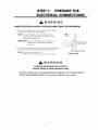
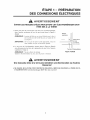
STEP 1: PREPARE THE
ELECTRICAL CONNECTIONS
_, WAR NI NG
AVOID ELECTRICAL SHOCK! THIS APPLIANCE MUST BE GROUNDED!
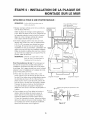
1. Locate the grounded electric outlet for this oven in the cabinet
above the oven, as shown in Figure 4 Detail.
NOTE: The outlet should be on a circuit dedicated to the
microwave oven 120V, 60Hz., AC only with a 15 or
20A fused electrical supply.
IMPORTANT: If you do not have the proper wall outlet, you
MUST have one installed by a qualified
electrician.
2. You will cut the power-supply-cord hole (shown in Figure 4 Detail)
later when you prepare the wall and upper cabinet in Step 4.
NOTE: Do not use an extension cord.
Keep the power cord dry and do not pinch or crush it.
Upper I
Cabinet
@
1
Power-Supply-Cord Hole
Grounded Outlet
( Inside Cabinet )
Figure 4 Detail
_,WARNING
Improper grounding could result in
electric shock or other personal injury.
• DO NOT, UNDER ANY CIRCUMSTANCES, REMOVE THE POWER SUPPLY
CORD GROUNDING PRONG! This appliance MUST be grounded!

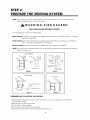
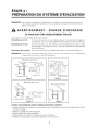
STEP 2:
PREPARE THE VENTING SYSTEM
NOTE: The ductwork you need for outside ventilation is not included with your oven. The standard ductwork
fittings and length are shown in Figure 9, page 9.
,WARNING:FIRE HAZARD
THIS OVEN MUST BE PROPERLY VENTED!
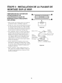
You may vent your oven in one of three ways:
Roof-venting If your oven is located on an outside wall near the roof, as in Figures 5 (3_/4'' x 10" duct)
and 6 (6" round duct.)
Wall-venting If your oven is located on an outside wall on the first floor of your house, as in Figure 7
(3_/4 '' X 10" duct) and Figure 6 (6" round duct.)
Room-venting If your oven is located on an inside wall of your house, as in Figure 8.
NOTE: If you choose the rear exhaust method (roof- or wall-venting), be sure there is enough clearance within the
wall for the exhaust duct.
oven
Roof-ventin{
"roofwenting"
duct _
through-the-roof
Figure 5
roof cap
6 _ min.
diameter
round duct
elbow
3 1/4"to round
du<_transition
3 1/4"to round
ductwork transition
Figure 6
cabinet
Wall-venting
"wall-venting"
/
3 t/4"xlO" through-the-wall
duct
Figure 7
cabinet
room-venting
Figure 8
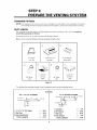
REMEMBER AS YOU INSTALL THE VENTING:
• Keep the length of the ductwork and the number of elbows to a minimum to ventilate your oven efficiently.
See examples on page 9.
• Keep the size of the ductwork the same.
• Do not install two elbows together.
• Use duct tape to seal all joints in the duct system.
• Use caulking to seal the exterior wall or roof opening around the cap.

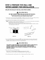
STEP 2:
PREPARE THE VENTING SYSYTEM
STANDARD FITTINGS
NOTE: If the existing duct is round, you must use a rectangular-to-round adapter, with a rectangular 3" extension
duct installed between the damper assembly and the adapter to prevent the exhaust damper's sticking.
DUCT LENGTH
The total length of the duct system, including straight duct, elbows, transitions, wall or roof caps must not
exceed the equivalent of 140 feet,
For best performance, do not use more than three 90 degree elbows.
Below are the standard fittings and their equivalent length in feet.
3 1/4"x 10"
to 6"=5ft.
2
3 1/4"x10" roof
cap=24ft.
3
3 1/4"x10" 90 °
elbow=25ft.
90° elbow
= 1Oft.
5
3 1/4"x10"
wall cap
=40ft.
6
45° elbow
=5ft.
7
3 1/4"x 10"
flat elbow
= 1Oft.
Figure 9
To calculate the equivalent length of each ductpiece used, see the examples below.
For 3 1/4"x10" SYSTEMS
3 1/4"x10" _ 6ft. | wall cap
90° elbow _i I _
Exam
1-3 1/4" x 10" 90° elbow = 25 ft.
1-Wall Cap = 40 ft.
8 feet straight duct = 8 ft.
TOTAL LENGTH = 73 ft.
_les
For 6" ROUND SYSTEMS
9O°elbows _ 6ft.-_1¢wall
transi_
1-transition
2-90 ° elbows
1-Wall Cap
8 feet straight
TOTAL LENGTH
cap
5ft.
20 ft.
40 ft.
8ft.
73 ft.

STEP 3:
PREPARE THE VENTING BLOWER
Your microwave oven is shipped with the blower assembled for roof venting. You need to adjust the blower if
you want wall-venting or room-vented (recirculating) installation.
, WARNING
ELECTRICAL SHOCK HAZARD! UNPLUG UNIT BEFORE WORKING ON IT,
• DO NOT PULL OR STRETCH THE BLOWER WIRING! Pulling and stretching the blower wiring could result in
electrical shock.
REMOVE THE MOUNTING PLATE:
1. Remove any shipping materials and parts from inside
the microwave oven.
2. Cover the countertop or cooktop with a thick,
protective covering to protect it from damage and dirt.
See Figure 10.
NOTE: If you have a free-standing range, disconnect it, move it
onto a piece of cardboard or hardboard and pull it away
from the wall, so that you can get closer to the upper
cabinet and back wall for easier measuring and drilling.
A thick, protective
covering
/
Figure 10
3. Remove mounting plate screw(s) (1 or 2 screws)
from the mounting plate as shown and discard
(see Figure 11).
4. This plate will be used to locate and mark the mounting
holes on the rear wall. (It will be used to locate and
mark the mounting holes on the rear wall.)
5. Locate exhaust adaptor, grease filters and hardware
packet.
6. At this point, remove any adhesive tape (if there is any),
on the exhaust adaptor, the grease filters and the
power supply cord.
ROOF-VENTED INSTALLATION:
This oven is shipped assembled for roof-vented. You
will need to install the exhaust adaptor regardless of
cabinet.
1. Attach the exhaust adaptor to the blower plate by
sliding it into the guides (see Figure 12).
Go to step 4 on page 13.
t-- Control panel side
Figure 11
..<__ J Exhaust
adaptor
I
L.= l ',
Back
ot oven
lO

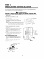
STEP 3:
PREPARE THE VENTING BLOWER
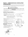
WALL-VENTED INSTALLATION:
1. Remove one blower unit mounting screw and one blower
plate screw. Remove the blower plate from cabinet.
See Figure 13.
2. Carefully lift the blower unit out of the microwave oven.
3. Use side cutters or tin snips to cut and remove knockouts
"B" from Back plate. Discard knockouts. Be careful net
to distort the plate. See Figure 14.
4. Reassemble the blower wire. See Figure 15.
5. Rotate the unit so that the exhaust ports face the rear of
the cabinet. See Figure 16. When you insert blower unit,
blower wire must be like Figure 16.
6. Place blower unit back into cabinet. Check that the
exhaust ports face towards the rear of the cabinet.
See Figure 17.
7. Reattach the blower plate to cabinet so the exhaust ports
and blower plate opening are aligned. Attach with one
blower unit mounting screw and then one blower plate
mounting screw. See Figure 18.
Figure 15
blower unit
back plate
blower plate
mounting screws
"_.\
blower unit
{Option> mounting screw
Figure 13
Parts "B"
Figure 14
Figure 16
blower
unit
exhaust
ports
11

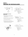
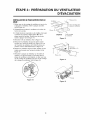
STEP 3:
PREPARE THE VENTING BLOWER
laust
ports
Figure 17
ROOM-VENTED (Recirculating)
INSTALLATION:
1. Remove one blower unit mounting screw and one
blower plate screw. Remove the blower plate from
cabinet. See Figure 19.
2. Carefully lift the blower unit out of the microwave oven.
3. Rotate blower unit 90 °so the exhaust ports face the
front of the cabinet. See Figure 20.
4. Place blower unit back into microwave oven.
5. Reattach blower plate to microwave oven. Attach with
the one blower unit mounting screw and then the one
blower plate mounting screw. See Figure 21.
mounting screws
blower unit
exhaust ports
<Option> blower unit
mounting screws
Figure 18
<Option> blo_/er unit
mounting screws
Figure 19
)late
mounting screws
Figure 20
blower
unit
<Option> blower unit
mounting screws
Figure 21
12

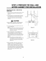
STEP 4: PREPARE THE WALL AND
UPPER CABINET FOR INSTALLATION
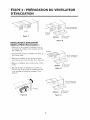
MEASURE AND TACK / TAPE UP THE
TEMPLATES
1. Using a plumb line and (metal) measuring tape, find and
mark the vertical center line on the back wall, as in
Figure 22.
2. Find and mark one or two points where the studs are
on the wall (Studs are normally 16 inches apart) and
then measure and mark the stud locations. If you
cannot find any wall stud, consult a local building
contractor.
CAUTION
DO NOT ATTEMPT TO INSTALL THE MICROWAVE
OVEN IF YOU CANNOT FIND A WALL STUD.
3. Line up the plumb line on the wall with the center line
on the mounting plate.
NOTE: Be sure the minimum width is 30 inches and the
distance from the top of the mounting plate to
the range or counter top is at least 30 inches.
See Figure 4 on page 4.
4. Center mounting plate on rear wall installation area by
lining up the plumb line on wall with centerline on
mounting plate. Make sure the minimum width is 30
inches and that the top of the mounting plate is located a
minimum of 30 inches above the cooking surface. See
Figure 23.
NOTE: If the cabinets are not plumb, adjust the
mounting plate to the cabinets. If the front edge
of the cabinet is lower than the back edge,
adjust the mounting plate to be level with the
cabinet front.
© o
Figure 22
Figure 23
5. Measure the bottom of the upper cabinet frame. Trim
the edges "A" "B" and "C" on the upper cabinet
template so that the template will fit on the bottom of
the upper cabinet. If upper cabinet has a recessed
frame, trim template so that it fits inside the recessed
area. Align the centerline of the upper cabinet template
with the centerline of the mounting plate; then securely
tape or tack the upper cabinet template in place.
See Figure 23
13

STEP 4: PREPARE THE WALL AND
UPPER CABINET FOR INSTALLATION
DRILLING THE HOLES IN THE WALL AND UPPER CABINET:
WARNING
BE VERY CAREFUL WHEN DRILLING HOLES INTO THE WALL.
Electrical wires could be concealed behind the wall covering
and if the drill hits them you could get an electric shock.
1. Find the points on the mounting plate labeled A, B, C, and D. Drill a 3/16" diameter hole at any of these points that
are in front of a wall stud. Drill a 3/4" diameter hole at any of these points that are over drywall.
2. Drill a 3/8" hole at points J and K on the upper cabinet template.
NOTE: If the bottom of the upper cabinet is recessed 3/4" or more, you will need 2"x2" filler blocks (not included) to
provide additional support for the bolts. See Figure 24.
• Mark the center of each filler block and drill a 3/8" diameter hole at the mark.
• Align filler blocks over the two openings in the top of the microwave oven cabinet and attach to cabinet
with masking tape. See Figure 25.
cabinet front! filler block bottomCabinetshelf _ _
filler
I-. _ block
\
Figure 24 Figure 25
3. Cut or drill a 2" diameter hole at the area marked M, "power supply cord hole" on the upper cabinet template.
If the upper cabinet is metal, you will need to cover the edge of the hole with the power supply cord bushing
(supplied) to prevent damage to the cord from the rough metal edge.
WARNING
YOU MUST COVER THE EDGE OF THE POWER SUPPLY CORD HOLE IN
A METAL CABINET WITH THE POWER SUPPLY CORD BUSHING.
FAILURE TO DO SO COULD RESULT IN DAMAGE TO THE CORD AND
ELECTRIC SHOCK,
4. Cut out the venting areas (with the saber saw):
• Roof-Vented: cut out the shaded area marked / on the upper cabinet template.
• Wall-Vented: go to STEP 5, INSTALL THE MOUNTING PLATE, located on page 16.
5. Use caulking compound to seal the exterior wall or roof opening around the wall cap or roof cap.
14

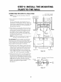
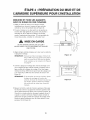
STEP 5: INSTALL THE MOUNTING
PLATE TO THE WALL
CONNECTING THE OVEN TO A WALL STUD:
NOTE: The oven must be connected to at least one
wall stud.
1. Draw a vertical line on the wall at the center of the 30"
wide space.
Use the mounting plate as the template for the rear
wall. Place the mounting plate on the wall, making sure
that the tabs are against the bottom of the cabinet. Line
up the notch and center line on the mounting plate to
the center line on the wall.
2. While holding the mounting plate with one hand, draw
circles on the wall at holes A, B, C and D. Four holes
must be used for mounting. If the holes are not used,
the installation will not be secure. Installer must use
these holes for proper installation. Use toggle bolts
through these holes unless one of them lines up with a
stud. Use a lag screw for studs.
NOTE: Draw a fifth circle inside area E, through one of
the holes to match the location of a stud.
Minimum 66"
From the Floor
For wall-vented: The oven requires a rear wall cutout
opening for the rear wall duct and the exhaust adaptor
must be attached to the mounting plate. See the next page
on how to prepare the rear wall cutout opening and the
exhaust adaptor/mounting plate for wall-vented.
3. Drill holes on the circles. If there is a stud, drill a 3/16"
hole for lag screws. Two or preferably four lag screws
at holes A and C or B and D must be used to secure
mounting plate to wall. If there is no stud, drill a 3/4"
hole for toggle bolts. Make sure to use at least 1 lag
screw at holes of area "E" in a stud, and 4 toggle bolts
at holes A, B, C and D in the drywall or the plaster.
4. Attach the plate to the wall. To use spring toggle head
bolts: Remove the toggle wings from the bolts. Insert
the bolts into the mounting plate and replace the spring
toggle head to 3/4" past the bolt ends. Insert the spring
toggle head into the holes in the wall to mount the
bracket. You may pull forward on the bracket to help in
tightening the toggle bolts. Tighten all bolts.
See Figure 27.
3/16" Hole on Studs
3/4" Hole on Drywall Only
I
/ Draw Lines
/ Mounting on Studs _
, ',
i / Plate _ Draw _ ,
/ Center Line
° oL_ oj 1o
C_ I ....................................................................................................Center Line -- l_i_
o o o o o o o o o cn o o o o o o o o o
t ' t
Support Tab Support Tab
Figure 26
Space More Than Wall Thickness
• I Toagle Wings
Mounting i _" ,11 I
Plate "_1 :' ,JllToggle Bolt L
m_ t_1_(__ _ EndB°lt
Figure 27
15

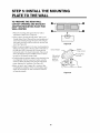
STEP 5: INSTALL THE MOUNTING
PLATE TO THE WALL
TO PREPARE THE REAR WALL
CUTOUT OPENING AND EXHAUST
ADAPTOR/MOUNTING PLATE FOR
WALL-VENTED:
1. Place the mounting plate against the rear wall as
described in step 5 item 1 (page 15).
2. Using a pencil, put dots through slots F and G, and
through holes H and I. Remove the mounting plate and
draw lines extending through the points. This will give
the location and size of the box cutout for the rear wall
duct. See Figure 28.
• Attach the exhaust adaptor to the rear mounting plate by
sliding it into the guides at the top center of the plate on
the wall side. Push in securely until it is past the top
locking tabs and in the lower locking tabs. Take care to
assure the damper hinge is installed so that it is at the
top and that the damper swings freely.
• Carefully guide the exhaust adaptor (now attached to the
mounting plate) into the house duct, before using the
screws to attach the plate to the wall. This will assure
proper alignment for installation. See Figure 29.
• Return to step 5, item 3 (page 15) to continue. After
completing the installation of the mounting plate, again
check the rear damper for free movement to assure it
will operate properly.
Exhaust Adaptor
Slide exhaust
adaptor into
guides on
rear panel.
Figure 28
Figure 29
Damper
(hinge side up)
. Mounting Plate
(wall side)
Guides
16

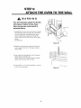
STEP 6:
ATTACH THE OVEN TO THE WALL
WARNING
You will need two people to lift this
microwave. Failure to use more
than one person could result in
personal injury.
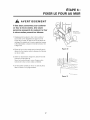
1. Carefully lift microwave oven and hang it on support
tabs (See Figure 26 on the page 15) at the bottom
of the mounting plate. Reaching through upper
cabinet, thread power supply cord through the
power supply cord hole in the bottom of the upper
cabinet.
See Figure 30.
2. Rotate the microwave oven upward so the top of
oven is against the bottom of the upper cabinet or
cabinet frame.
__ power cord
Figure 30
3. Insert a bolt down through each hole in the upper
cabinet bottom. See Figure 31.
Tighten the bolts until the gap between the upper
cabinet and microwave oven is closed.
4. If wall vented or room vented installation is used, go
to No.7 on the next page.
Figure 31
17

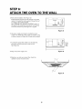
STEP 6:
ATTACH THE OVEN TO THE WALL
5. Roof vented installation: See Figure 32
Install ductwork through the vent opening in the upper
cabinet. Complete the venting system through the roof
according to the method needed.
See "PREPARE THE VENTING SYSTEM," step 2 on
the page 8. Use caulking to seal exterior roof opening
around the exhaust cap. See Figure 6 on page 8.
6. Use power supply cord clamp to bundle the power
supply cord. Install the power supply cord clamp, using
a screw as shown in Figure 33, to inside of the cabinet.
7. To install the grease filter: Slide it into the slide slot,
then push up and toward oven center to lock.
See Figure 34.
8. Plug in the power supply cord.
[
damper
ii,--
Figure 32
_t p°wer
supply
cord
clamp
ii,--
Figure 33
9. Read your use and care manual, then check the
operation of your microwave oven.
Figure 34
18

I_lectromdnagers
Four b micro-ondes avec hotte
Instructions d'installation
For Models: HMV9302, HMV9303, HMV9305. HMV9306 HMV9307
PRIEREDELIRETOUTESLESINSTRUCTIONSAVANTDEPROCEDER,A,[.'iNSTALLATION.
IMPORTANT:Conserverces instructionspourque I'inspecteurlocalpuissev6rifierI'installation.
INSTALLATEUR:Pri_rede remettreces instructionsau propri6taireapr#sJ'installation.
PROPRIETAIRE:Conserverces instructionspourr6f_rencefuture.
Imprim& en Cor&e
Piece n°: 3828W5U0503

VOTRE sr:..CUR|TP:..D'ABORD
AVANT DE COMMENCER
• Uinstaliateur est responsable de faire une installation adequate!
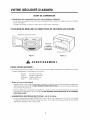
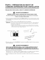
- Lire le manuel au complet avant de commencer. L'_tiquette portant le num_ro de modele se trouve sur le devant
du four. Voir figure 1.
La plaque de montage se trouve a I'arriere du four a micro-ondes. Voir figure 2.
S'ASSURER DE BIEN LIRE LES DIRECTIVES DE SI_CURITI_ QUI SUIVENT :
Etiquette de num&ro de mod&le
r-======l
Figure 1
Plaque de J
montage
(La deposer
du four avant
I'instaliation)
Arri&re du four
Figure 2
AVERTISSEMENT
POUR VOTRE SI:!:CURIT¢: :
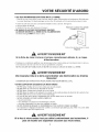
• II faut deux personnes pour installer ce four. II est Iourd et peut entra'[ner des blessures corporelles s'il n'est pas
manipule ad_quatement. Les dimensions du four sont
Hauteur : 16 7/16 po (417 mm)
Largeur : 29 15/16 po (760 mm)
Profondeur : 15 5/8 po (397 mm)
Poids : 60 Ib (27,25 kg)
• Eviter les chocs _lectriquesZ
- Avant de percer lemur, noter I'emplacement des prises de courant et o_ des ills electriques pourraient _tre
dissimul6s derriere la paroi. IL Y A DES RISQUES D'ICLECTROCUTION si I'on touche & des ills _lectriques
avec la m_che de la perceuse.
- Trouver le disjoncteur ou le fusible correspondant et couper le courant aux circuits _lectriques qui pourraient
_tre affect_s par I'installation de ce four. IL Y A DES RISQUES D'¢LECROCUTION SI LE COURANT
N'EST PAS COUPe.
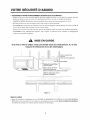
* ALIMENTATION ELECTRIQUE DE CE FOUR : 120 V CA 60 Hz,
- II faut une alimentation _lectrique DISTINCTE de 120 V, 60 Hz, CA seulement de 15 ou 20 A, avec fusible
ou disjoncteur (situee dans I'armoire au dessus du four & micro-ondes, le plus pres possible du four) servant
uniquement & alimenter le four & micro-ondes.
La page est en cours de chargement...
La page est en cours de chargement...
La page est en cours de chargement...
La page est en cours de chargement...
La page est en cours de chargement...
La page est en cours de chargement...
La page est en cours de chargement...
La page est en cours de chargement...
La page est en cours de chargement...
La page est en cours de chargement...
La page est en cours de chargement...
La page est en cours de chargement...
La page est en cours de chargement...
La page est en cours de chargement...
La page est en cours de chargement...
La page est en cours de chargement...
-
 1
1
-
 2
2
-
 3
3
-
 4
4
-
 5
5
-
 6
6
-
 7
7
-
 8
8
-
 9
9
-
 10
10
-
 11
11
-
 12
12
-
 13
13
-
 14
14
-
 15
15
-
 16
16
-
 17
17
-
 18
18
-
 19
19
-
 20
20
-
 21
21
-
 22
22
-
 23
23
-
 24
24
-
 25
25
-
 26
26
-
 27
27
-
 28
28
-
 29
29
-
 30
30
-
 31
31
-
 32
32
-
 33
33
-
 34
34
-
 35
35
-
 36
36


