
Wattstopper
®
Low Voltage Occupancy Sensor (Version 3)
Installation Instructions • Instructions d’Installation • Instrucciones de Instalación
No: 24214 – 09/16 rev. 1
Catalog Number • Numéro de Catalogue • Número de Catálogo: WPIR
Country of Origin: Made in China • Pays d’origine: Fabriqué en Chine • País de origen: Hecho en China
SPECIFICATIONS
Voltage ...................................................................24VDC
Current Consumption ............................................... 15mA
Power Supply ............................. Wattstopper Power Pack
Time Delay Adjustment ............................... 30sec-30mins
Sensitivity Adjustment ..........................................min-max
UNIT DESCRIPTION
The WPIR is a 24VDC Passive Infrared (PIR) occupancy sensor which controls lighting or HVAC systems based on occupancy.
PIR sensing systems are passive systems that react to changes in infrared energy (body heat) within the coverage area. When the
sensor detects a change in the infrared heat radiated within the controlled area, lighting or HVAC systems are switched ON through a
WattStopper Power Pack. Once occupants leave an area, the lights of HVAC systems are switched OFF after a user-adjustable time
delay of 30 seconds to 30 minutes.
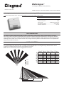
COVERAGE PATTERN
The coverage pattern is determined by the mounting position, mounting height and viewing pattern of the PIR sensor. When increasing
the mounting height of the sensor the area of coverage increases dramatically. For covering down long aisles the sensor can be
mounted on a vertical surface and zones 4 and 5 will view over 50 feet.
NOTE: Zone 5 detects directly below and slightly behind the sensor.
=RQH
=RQH
=RQH
=RQH
=RQH
=RQH
=RQH
=RQH
=RQH
=RQH

2
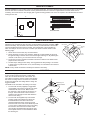
SENSOR PLACEMENT
Standard installation is onto a ceiling, wall, or an electrical junction box. The sensor should be mounted so that the lens on the sensor
faces the area to be controlled. The sensor must be positioned so there is a clear line of sight between it and the areas that it is
controlling. The sensor will not “see” through glass. Typical mounting position is the corner of a space to be controlled with the sensor
looking into the area.
Sensor
15'
15'
Individual Ofce Placement
:3,56HQVRU
%RRNVWDFN
)L[WXUH
Aisle Placement
SENSOR ADJUSTMENT
Sensor controls are beneath a cover that fits across the sensor. SENSE denotes sensitivity
adjustment; fully clockwise is 100% and fully counterclockwise is minimum sensitivity. TIME
denotes time delay; fully clockwise is 30 minutes and fully counterclockwise is 30 seconds.
The LED will flash each time motion is sensed. The rectangle slot is for the bypass pin,
which is a small pin for use in the event of a failure (see the On Override section on the
following page).
1. Set the time to 30 seconds, fully counterclockwise.
2. Set the sensitivity to 100%, fully clockwise. Stand still. In approximately 30 seconds
the lights should go off. Move in the area and the lights should go on. By watching the
red LED on the sensor, you can test the area of coverage.
3. The amount of motion needed for activation increases in relation to the distance that
people are from the sensor.
4. The last step is setting the time delay. The suggested time delay setting is 15 minutes.
In areas where very little motion occurs, the time delay can increased to the maximum
of 30 minutes.
NOTE: Factory default is maximum sensitivity and maximum time delay.
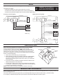
MOUNTING
In most mounting applications, the sensor is attached
to the mounting surface with screws or toggle blots
which fit in the holes beneath the control cover. The
low voltage connections must be made on the opposite
side of the mounting surface. The wires are connected
to the Power Pack with low voltage Class 2 wiring. We
suggest 22 AWG.
The WPIR can be mounted to the ceiling in two ways:
1. To mount with screws (supplied) or toggle bolts
(not supplied): The screws or bolts fit in the holes
underneath the control cover. Make a hole in
the ceiling tile - large enough for the wires to go
through - where the sensor is to be mounted.
Guide the wires through the hole and attach the
sensor to the ceiling.
2. To mount with the supplied snap-on threaded
bracket, washer and retaining nut: Attach the
threaded bracket to the back of the sensor
(squeeze thebracket at the mounting end and
insert into slots on the back of the WPIR unit). Drill
or cut a 13/16” or slightly larger, hole in the ceiling
tile where the sensor is to be mounted. Guide
wires and the threaded bracket through the hole.
Put the plastic washer on the bracket then attach
the retaining nut.
6(16(
7,0(
/(',QGLFDWRU
0RXQWLQJ
+ROHV
6HQVLWLYLW\
$GMXVWPHQW
7LPH'HOD\
$GMXVWPHQW
6HQVRU
:LQGRZ
2YHUULGH
&HLOLQJ
5HWDLQLQJQXW
3ODVWLFZDVKHU

3
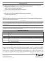
WIRING
Refer to the wiring diagrams on the next page for the following procedures:
Connect the low voltage:
• RED wire (+24VDC) from power pack to RED wire on sensor.
• BLACK wire from power pack to BLACK wire on sensor (Control Return).
• BLUE wire from power pack to BLUE wire on sensor (Control Output 24VDC).
SENSOR ADJUSTMENT
Sensor controls are beneath a cover that fits across the sensor. SENSE
denotes sensitivity adjustment; fully clockwise is 100% and fully
counterclockwise is minimum sensitivity. TIME denotes time delay; fully
clockwise is 30 minutes and fully counterclockwise is 30 seconds. The LED
will flash each time motion is sensed. The rectangle slot is for the bypass
pin, which is a small pin for use in the event of a failure (see the On Override
section on the following page).
1. Set the time to 30 seconds, fully counterclockwise.
2. Set the sensitivity to 100%, fully clockwise. Stand still. In approximately
30 seconds the lights should go off. Move in the area and the lights
should go on. By watching the red LED on the sensor, you can test the
area of coverage.
3. The amount of motion needed for activation increases in relation to the
distance that people are from the sensor.
4. The last step is setting the time delay. The suggested time delay setting
is 15 minutes. In areas where very little motion occurs, the time delay can
increased to the maximum of 30 minutes.
NOTE: Factory default is maximum sensitivity and maximum time delay.
IMPORTANT START-UP INFORMATION
When the power pack is installed and the power is connected , the load comes on for 60 seconds. Regardless of the occupancy,the warm up
time occurs during power on.
If the sensor detects occupancy during the warm up ,the load stays ON as long as it continue to detect motion , plus the time delay.
If no occupancy is detected during the warm-up, the load turns OFF after the initial 60 second warm-up time.
6(16(
7,0(
/(',QGLFDWRU
0RXQWLQJ
+ROHV
6HQVLWLYLW\
$GMXVWPHQW
7LPH'HOD\
$GMXVWPHQW
6HQVRU
:LQGRZ
2YHUULGH
:KLWH1HXWUDO
5HG/RDG
5HG/LQH
:KLWH
%ODFN+RW
1
32:(53$&.
5HG
%ODFN
%OXH
6ZLWFK
%/8&RQWURO2XWSXW9'&
%/.&RQWURO5HWXUQ
5('9'&
/LJKWLQJ
/RDG
:3,5ZLULQJ
Occupancy Controlled Lighting
:KLWH1HXWUDO
5HG/RDG
5HG/LQH
:KLWH
%ODFN+RW
1
32:(53$&.
5HG
%ODFN
%OXH
6ZLWFK
&RQWURO2XWSXW9'&%/8
9'&5('
/LJKWLQJ
/RDG
:KLWH1HXWUDO
5HG/RDG
5HG/LQH
:KLWH
%ODFN
+RW
1
32:(53$&.
5HG
%ODFN
%OXH
6ZLWFK
&RQWURO5HWXUQ%/.
&RQWURO2XWSXW9'&%/8
9'&5('
&RQWURO5HWXUQ%/.
/LJKWLQJ
/RDG
:3,5
Multiple Sensors and Lighting
WARNING: TURN THE POWER OFF
AT THE CIRCUIT BREAKER BEFORE
WIRING POWER PACKS OR SENSORS.

800.879.8585
www.legrand.us/wattstopper
No. 24214 – 09/16 rev. 1
© Copyright 2016 Legrand All Rights Reserved.
© Copyright 2016 Tous droits réservés Legrand.
© Copyright 2016 Legrand Todos los derechos reservados.
Wattstopper warranties its products to be free
of defects in materials and workmanship for a
period of five (5) years. There are no obligations
or liabilities on the part of Wattstopper for
consequential damages arising out of, or in
connection with, the use or performance of this
product or other indirect damages with respect
to loss of property, revenue or profit, or cost of
removal, installation or reinstallation.
Wattstopper garantit que ses produits sont
exempts de défauts de matériaux et de fabrication
pour une période de cinq (5) ans. Wattstopper
ne peut être tenu responsable de tout dommage
consécutif causé par ou lié à l’utilisation ou
à la performance de ce produit ou tout autre
dommage indirect lié à la perte de propriété, de
revenus, ou de profits, ou aux coûts d’enlèvement,
d’installation ou de réinstallation.
Wattstopper garantiza que sus productos
están libres de defectos en materiales y mano
de obra por un período de cinco (5) años. No
existen obligaciones ni responsabilidades por
parte de Wattstopper por daños consecuentes
que se deriven o estén relacionados con el
uso o el rendimiento de este producto u otros
daños indirectos con respecto a la pérdida
de propiedad, renta o ganancias, o al costo
de extracción, instalación o reinstalación.
WARRANTY INFORMATION INFORMATIONS RELATIVES À LA GARANTIE INFORMACIÓN DE LA GARANTÍA
TROUBLESHOOTING
If the lights will not go OFF after the time out period, and the LED does not come on when moving in front of the sensor:
1. Disconnect the wire to the power pack, if lights do not go OFF, check Power Pack connection:
• voltage going in (120 or 277AC)
If there is no power, check the breaker has been turned back on.
• 24VDC coming out for the power pack (Red and Black).
If there is no power, check that the power pack has been wired correctly.
2. If lights still do not go off, call 800.879.8585 to talk to Technical Support.
Motion occurs in the room and the lights do not turn on:
1. Check the sensitivity setting and increase as needed.
2. Check connections between sensors and power packs.
3. If there is still a problem, check to see that there is 24VDC at the sensor (Red and Black).
• If 24VDC is present, replace sensor.
• If 24VDC is not present, check Power Pack.
4. If lights still do not turn on, call 800.879.8585 to talk to Technical Support.
Lights cycle on and off:
If the lights go off, and immediately turn back on, the sensor is picking up the infrared energy change from the lights. Adjusting the
sensitivity down slightly until the lights stay off will usually eliminate this problem. If not, use the masking tape provided to mask (block
out) the part of the lens window that views the lights.
ON OVERRIDE:
Next to the Sensitivity Adjustment dial is an opening that contains a jumper pin. Remove this jumper if you want to override the switching
circuit and have the lights and the LED remain on regardless of occupancy. Replacing the jumper in the same position, will reactivate
the switching circuit.
OVERLOAD PROTECTION
The occupancy sensor has a built in overload protection function that will automatically turn off the control output when the load current
exceeds 200mA. The LED will blink rapidly for 5 seconds to provide a visual indication of an overload condition. When the load current
is corrected or returns to normal, the control output will turn back on.
ORDERING INFORMATION
Catalog Description
WPIR PIR Occupancy Sensor
BZ-50 Power Pack: 120/277VAC, 50/60Hz, 20A ballast or incandescent
BZ-150 Power Pack: 120/277VAC, 50/60Hz, 20A ballast or incandescent, with Hold-On and Hold-Off capability
BZ-200 Power Pack: 120/277VAC, 50/60 Hz, 20A Ballast/ELV/MLV/Incandescent/LED, 16A, E-Ballast/CFL/Plug Load
BZ-250 Power Pack: 120/277VAC, 50/60 Hz, 20A, Ballast/ELV/MLV/Incandescent/LED, 16A E-Ballast/CFL/Plug Load,
with Hold-On/Hold-Off capability
BZ-250-347 Power Pack: 120/347VAC, 50/60 Hz, 16A Ballast/ELV/MLV/Incandescent/LED/ E-Ballast/CFL, 15A Plug Load,
with Hold-On/Hold-Off capability
-
 1
1
-
 2
2
-
 3
3
-
 4
4


wattstopper WPIR Low Voltage Ceiling Sensor Guide d'installation
- Taper
- Guide d'installation
- Ce manuel convient également à
dans d''autres langues
Documents connexes
-
wattstopper CI-200 PIR Low Voltage Occupancy Sensor Mode d'emploi
-
-
-
-
wattstopper DW-100/200 Dual Technology Wall Switch Occupancy Sensor Mode d'emploi
-
-
-
Legrand WS-301-347-I Guide d'installation
-
wattstopper FS-555 Mode d'emploi