Cembre HT-TC051Y Manuel utilisateur
- Catégorie
- Outils électroportatifs
- Taper
- Manuel utilisateur

1
ENGLISH
FRANÇAIS
DEUTSCH
ESPAÑOL
ITALIANO
18 M 032
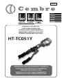
HYDRAULIC CUTTING TOOL
COUPE CABLE HYDRAULIQUE
HYDRAULISCHES SCHNEIDWERKZEUG
HERRAMIENTA HIDRAULICA DE CORTE
UTENSILE OLEODINAMICO DA TAGLIO
HT-TC051Y
OPERATION AND MAINTENANCE MANUAL
NOTICE D'UTILISATION ET ENTRETIEN
BEDIENUNGSANLEITUNG
MANUAL DE USO Y MANTENIMIENTO
MANUALE D'USO E MANUTENZIONE

2
1
– Tool type
– Outil type
– Handwerkzeug Typ
– Herramienta tipo
– Tipo di utensile
– Year
– Année
– Jahr
– Año
– Anno
2
3
1 2
3
1 2 3
4
– max cutting diam.
– ø maxi de coupe
– max. Schneid. ø
– ø max de corte
– ø max di taglio
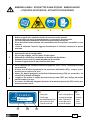
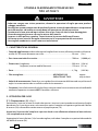
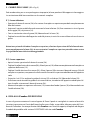
WARNING LABELS - ETIQUETTES SIGNALETIQUES - WARNSCHILDER
- ETIQUETAS DE ATENCION - ETICHETTE D'AVVERTENZA
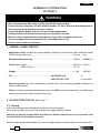
TYPE
HT-TC051Y
Ø MAX
50 mm (2 inch)
2530 G.T
1
– Before using the tool, carefully read the instructions in this manual.
– Avant d’utiliser cet outil, lire attentivement les instructions de cette notice.
– Vor Inbetriebnahme unbedingt die Bedienungsanleitung durchlesen.
– Antes de utilizar la herramienta, leer atentamente las instrucciones contenidas en este
manual.
– Prima di utilizzare l’utensile, leggere attentamente le istruzioni contenute in questo
manuale.
2
– Keep hands clear of cutting blades.
– Au cours du coupage, tenir les mains loin des lames.
– Während des Schneidens, die Hände von den Messern fernhalten.
– Durante el corte, tener las manos alejadas de las cuchillas.
– Durante il taglio, tenere le mani lontane dalle lame.
3
4
– Ensure appropriate Personal Protective Equipment (PPE) is used - including hand and
eye protection.
– Assurez-vous d’utiliser équipements de protection individuelle (EPI) y compris la pro-
tection pour les mains et les yeux.
– Achten Sie darauf geeignete persönliche Schutzausrüstung (PSA) zu verwenden, ein
schließlich für Hände und Augen.
– Asegúrese de utilizar el equipo de protección personal (EPP) que incluye protección
para las manos y los ojos.
– Assicurarsi di utilizzare adeguati dispositivi di protezione personale (DPI) incluse pro-
tezioni per mani e occhi.

3
ENGLISH
HYDRAULIC CUTTING TOOL
HT-TC051Y
1. GENERAL CHARACTERISTICS
– Application range: suitable for cutting copper, aluminium, aluminium steel reinforced cables
(ACSR) having a max ø of ............................................................................................... 50 mm (2 in.)
– Rated operating pressure: ........................................................................................... 700 bar (10,000 psi)
– Dimensions: length ............................................................................................. ........... 503 mm (19.8 in.)
width 129 mm ........................................................................................ (5.1 in.)
– Weight: ................................................................................................................................. 4,7 kg (10.3 lbs)
– Oil: .......................................................................................AGIP ARNICA 32 or
SHELL TELLUS TX 32 or equivalent
– Advancing speed: the tool automatically switches from a fast advancing speed of blades to a
slower cutting speed.
– Safety: the tool is provided with max pressure valve; MPC1 special manometer, is available upon
request to check the proper setting of the valve.
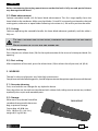
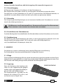
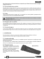
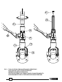
2. INSTRUCTIONS FOR USE (Ref. to Fig. 1)
2.1) Setting
Insert the cable between the blades at the desired cutting point.
For a running cable, press latch (28) and open the upper blade assembly.
Warning: the opening of upper blade assembly must be done when the tool is in rest position, with
the lower blade (18) completely retracted.
With the cable on the lower blade (18), close the upper blade assembly and secure the latch (28).
• Wear eye protection. Metal chips can fly from blades when cutting.
• Do not cut short, free pieces of steel reinforced cables (ACSR) as they may fly off dangerously,
causing injury to the operator or persons nearby.
• Inspect the blades before each use. Do not use damaged blades.
• Damaged blades can break and cause injury or damage to the tool.
• Work in a clean, uncluttered area. Keep persons away from immediate work area.
• Use this cutting tool for the manufacturer’s intended purpose only.
• Do not cut live cables or conductors.
WARNING

4
ENGLISH
CANVAS BAG
Before commencing the cutting operation ensure that the latch is fully secured: partial closure
may damage the tool head.
2.2) Blade advancement
Operate moveable handle (44) for lower blade advancement. This first stage rapidly closes the
lower blade to the conductor. Make sure that blades (18 and 23) are exactly positioned on desired
cutting point, otherwise re-open blades following instructions as § 2.4 and re-position the cable.
2.3) Cutting
Continue operating the moveable handle, the lower blade advances gradually until the cable is
fully cut.
The Tool is designed for cuTTing copper, aluminium and aluminium sTeel rein forced
cables.
do noT aTTempT To cuT guy wire and ground rod.
2.4) Blade opening
Press the pressure release lever (58) for the rapid retraction of the ram and subsequent blade (18)
opening.
2.5) Rest setting
After completion of the work, press the release lever (58) to release the oil pressure (ref. § 2.4).
3. WARNING
The tool is robust and requires very little daily maintenance.
Compliance with the following points, should help to maintain the optimum performance of the tool:
3.1) Accurate cleaning
Dust, sand and dirt are a danger for any hydraulic device.
Every day, after use, the tool must be cleaned with a clean cloth, taking care to remove any residual,
especially close to pin and moveable parts.
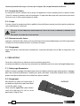
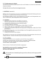
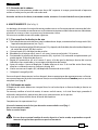
3.2) Storage
When not in use, the tool should be
stored and transported in the canvas
bag, to prevent damage.
Canvas bag: ref. 010; size
545 x 160 mm (21.4 x 6.3 in.);
weight 0,15 kg (0.3 lbs).

5
ENGLISH
3.3) Head rotation
For ease of operation, the tool head can rotate through 90°.
Warning: Do not attempt to turn the head if the hydraulic circuit is pressurised.
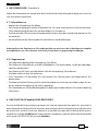
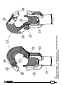
4. MAINTENANCE (Ref. to Fig. 2)
Air in the hydraulic circuit may affect the performance of the tool; e.g: no advancement or slow
advancement of the lower blade; lower blade pulsating.
In this case proceed as follows:
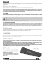
4.1) To purge air bubbles from hydraulic circuit
a – Hold tool upright in a vice with handles open (Fig. 2).
b – Unscrew the main handle (03) from the body (12) to expose the rubber oil reservoir (02).
c – Remove reservoir cap (01).
d – Operate moveable handle, several times, in order to advance the ram (14).
e – Press the pressure release lever (58) to retract the ram (14), discharge oil pressure from the circuit
and return all oil to the reservoir.
f – Repeat points (d - e) five times, to ensure all air bubbles in the hydraulic circuit are purged into
the reservoir.
g – If the oil level is low, top up as directed in § 4.2.
h – Remove all air from reservoir (02) and fit cap (01).
i – Assemble main handle (03) to tool body.
If the tool continues to malfunction return the tool for service/repair as detailed in § 6.
4.2) Oil top up
Every six months check the oil level in the reservoir. If necessary, top up the oil level to the top lip
of the reservoir and remove all air from reservoir, see § 4.1, points a, b, c, e, g, h and i.
Always use clean recommended oil, see § 1.
Do not use old or recycled oil.
Do not use hydraulic brake fluid.
Ensure that disposal of used oil, is in accordance with current legislation.

6
ENGLISH
5. BLADE REPLACEMENT (Ref. to Fig. 3 )
After extended use, the blades may loose their cutting edge.
Replace the blades as follows:
5.1) Lower blade
– Release latch (28), open the head.
– Operate moveable handle to advance the lower blade (18) until holding screw (29) is visible on
the ram (14).
– Using a flat blade, screwdriver remove the holding screw (29) and release the lower blade (18).
– Insert the new blade and fit the holding screw.
Warning: before closing the head release the oil pressure and retract the lower blade (18), otherwise
the tool head assembly may hit and damage the lower blade.
5.2) Upper blade
– Release latch (28), open the head.
– Remove the circlip (20) and extract the head pin (19), enough to release the tool head assembly.
– Remove circlip (25) and pin (26), to release the latch (28). Remove latch spring from the upper
blade.
– Unscrew the 4 screws (21), remove the left hand guide (22), the right hand guide (24) and release
the blade (23).
– Fit the left and right hand guides to the new blade. Place the spring into its seat and refit the latch.
– Fit the blade assembly to the head (13), fully insert the pin (19) and secure with the circlip (20).
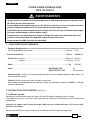
6. RETURN TO Cembre FOR OVERHAUL
In the case of a breakdown contact our Area Agent who will advise you on the problem and give
you the necessary instructions on how to dispatch the tool to our nearest service Centre; if possible,
attach a copy of the Test Certificate supplied by Cembre together with the tool or fill in and attach
the form available in the “ASSISTANCE” section of the Cembre website.

7
ENGLISH
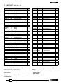
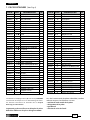
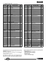
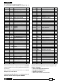
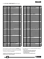
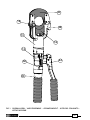
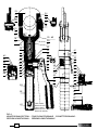
7. PARTS LIST (Ref. to Fig. 4)
The items marked ( ) are those Cembre recommend
replacing if the tool is disassembled.
These items are supplied on request in the “HT-TC051Y Spare
Parts Package”.
The guarantee is void if parts used are not Cembre
original spares.
Code N° Item DESCRIPTION Qty
6800040 01
RESERVOIR CAP
1
6720050 02
OIL RESERVOIR
1
6480055 03
MAIN HANDLE
1
6360250
04
O-RING
1
6740100
05
5/32” BALL
1
6520160
06
SUCTION SPRING
1
6740020
07
1/4” BALL
1
6520200
08
SPRING
1
6340590 09
BALL POSITIONING DOWEL
1
6360270
10
O-RING
1
6040181
11
BACK-UP RING
1
6160027 12
BODY
1
6860101 13
HEAD
1
6620169
14
RAM
1
6361810
15
SEAL
1
6641020
16
M 6 COPPER WASHER
1
6900334
17
M 6x30 SCREW
1
6420235 18
LOWER BLADE
1
6560691 19
UPPER BLADE PIN
1
6040421 20
Ø 10 CIRCLIP
1
6900315
21
M 6x16 SCREW
4
6370141
22
LOWER BLADE LEFT GUIDE
1
6420245
23
UPPER BLADE
1
6370151
24
LOWER BLADE RIGHT GUIDE
1
6700140
25
CIRCLIP
1
6560701
26
LATCH PIN
1
6520460
27
SPRING
1
6200051
28
LATCH
1
6760294 29
BLADE HOLDING SCREW
1
6080051 30
RAM BUSHING
1
6522314 31
BLADE RETURN SPRING
1
6360266
32
O-RING
1
6360161
33
O-RING
1
6560262 34
MOVABLE HANDLE PIN
2
6700060
35
CIRCLIP
4
6040101
36
BACK-UP RING
1
6362020
37
SEAL
1
Code N° Item DESCRIPTION Qty
6620090 38 PUMPING RAM 1
6360240
41
O-RING 1
6340590 40 BALL POSITIONING DOWEL 1
6520200
43
SPRING 1
6740020
42
1/4” BALL 1
6232038 43 LABEL (TG. 0351) 1
6480171 44 MOVEABLE HANDLE 1
6380200 45 HANDLE GRIP 1
6895046 46 MAX PRESSURE VALVE 1
6040080
47
BACK-UP RING 1
6360140
48
O-RING 1
6020027 49 PRESSURE RELEASE PIN 1
6600020 50 SPRING LOADED PIN 1
6520280
51
SPRING 1
6360120
52
O-RING 1
6740120
53
7/32” BAL 1
6600100 54 BALL SUPPORT 1
6520520
55
SPRING 1
6360166
56
O-RING 1
6900341 57 M 8x10 SCREW 1
6440100 58 PRESSURE RELEASE LEVER 1
6760100 59 ø 3x16 SPLIT PIN 1
6232409 60 METAL LABEL (TG. 0503) 1
6650118 61 RIVET ø 2,5x3,5 2
6635011 62 PRESSURE RELEASE PIN 1
6520861 63 SPRING 1
6340720 64 PRESSURE RELEASE DOWEL 1
6520160
65
SUCTION SPRING 1
6740100
66
5/32" BALL 1
6641020
67
M 6 COPPER WASHER 1
6900601 68 SUCTION SCREW 1
6760147 69 ø 3x24 SPLIT PIN 1
6232415 70 TG. 0616 WARNING LABEL 1
6860133
HEAD ASSEMBLY
6780272
COMPLETE RAM
6000088
SPARE PARTS PACKAGE
When ordering spare parts always specify the fol-
lowing:
- code number of item
- name of item
- type of tool
- tool serial number

8
FRANÇAIS
COUPE-CABLE HYDRAULIQUE
TYPE HT-TC051Y
1. CARACTERISTIQUES GENERALES
– Domaine d'application: conçu pour sectionner des câbles en cuivre, aluminium, aluminium acier
(ACSR) de diamètre maximum..................................................................................... 50 mm (2 in.)
– Pression nominale: ........................................................................................................... 700 bar (10,000 psi)
– Dimensions: hauteur ..................................................................................................... 503 mm (19.8 in.)
largeur ....................................................................................................... 129 mm (5.1 in.)
– Poids: .................................................................................................................................... 4,7 kg (10.3 lbs)
– Huile: ......................................................................................... AGIP ARNICA 32 ou
SHELL TELLUS TX 32 ou équivalent
– Avance rapide: l'outil passe automatiquement de la vitesse rapide d'approche des lames, à la
vitesse lente de coupe.
– Sécurité: l'outil est pourvu d'une valve de surpression.
Pour vérifier le bon fonctionnement de cette valve, un manomètre spécial, réf. MPC1, est dispo-
nible à la demande.
2. INSTRUCTIONS D'UTILISATION (Voir Fig. 1)
2.1) Mise en service
Positionner le conducteur entre les lames de l'outil à l'endroit souhaité pour la coupe.
Si le câble est passant, il sera alors nécessaire de tirer le loquet (28) de façon à ouvrir la tête (lame
supérieure).
Attention: ne jamais ouvrir la tête du coupe-câble tant que la lame inférieure (18) n'est pas com-
plètement descendue.
Positionner le câble sur la lame inférieure, et refermer la tête à l'aide du loquet (28).
AVERTISSEMENTS
• Toujours porter une visière de protection pendant les opérations de coupe, car de petits éclats
de câbles peuvent être propulsés.
• Ne pas couper de morceaux trop courts, des câbles en aluminium-acier car ils pourraient être
projetés dangereusement et blesser l’opérateur ou une personne proche.
• Contrôler les lames avant chaque utilisation. Ne pas utiliser l’outil avec une lame endommagée.
• Les lames endommagées peuvent abîmer l’outil.
• Travailler dans un espace propre et ordonné. Eloigner les personnes de la zone de travail.
• N’utiliser cet outil que dans les conditions indiquées par le fabricant.
• Ne pas couper de câble sous tension électrique.

9
FRANÇAIS
SACOCHE
Avant de procéder à la coupe, s'assurer que le loquet (28) soit parfaitement enclenché.
2.2) Avance des lames
En actionnant le bras mobile (44), le piston se déplace en vitesse rapide jusqu'à ce que les lames
(18 et 23) soient en contact avec le conducteur. Si la position de coupe n'est pas bonne, desserrer
les lames (voir § 2.4) et repositionner le câble.
2.3) Coupe
En poursuivant la manœuvre du bras mobile, la lame inférieure monte jusqu'à ce que le conducteur
soit complètement sectionné.
ceT ouTil n’a éTé conçu que pour couper des câbles en cuivre, aluminium, aluminium-acier
(acsr).
ne coupez pas barres ou cables en acier.
2.4) Réouverture des lames
Appuyer sur le levier (58), situé sur le corps afin d'activer la valve de décompression (49) et permettre
le retour de la lame inférieure dans sa position de repos.
2.5) Rangement
Après l'utilisation, l'outil doit être ramené dans sa position de repos (voir § 2.4), et rangé dans son
coffret.
3. PRECAUTIONS
Cet outil est robuste et ne nécessite aucun entretien particulier.
Les recommandations suivantes sont néanmoins souhaitables pour lui assurer une longévité optimum:
3.1) Nettoyage élémentaire
Veiller à toujours protéger l'outil de la poussière, du sable et de la boue qui représentent un danger
pour tout système hydraulique. Chaque jour, après utilisation, il doit être nettoyé avec un chiffon
propre, tout particulièrement aux endroit des pièces mobiles.
3.2) Rangement
Afin d'éviter les chocs et la poussière, il
est de bonne règle de ranger l'outil dans
sa sacoche après usage.
Cette sacoche (type 010) a pour dimen-
sions 545 x 160 mm (21.4 x 6.3 in.) et un
poids de 0,15 kg (0.3 lbs).

10
FRANÇAIS
3.3) Rotation de la tête
La tête de ce coupe-câble pivote à 90°, permettant à l'utilisateur de toujours travailler dans les
meilleures conditions.
Attention: ne jamais forcer la rotation de la tête lorsque le circuit hydraulique est sous pression.
4. ENTRETIEN (Voir Fig. 2)
Le seul problème nécessitant une intervention qui peut parfois être rencontré est la présence d'une
bulle d'air dans le circuit hydraulique.
Cet incident est caractérisé par un mauvais fonctionnement de l'outil au cours de la montée en
pression: soit la lame inférieure ne monte pas, soit elle progresse très lentement, soit elle avance
par à-coups.
Dans ce cas, procéder de la façon suivante:
4.1) Elimination de bulles d'air
a – Serrer l'outil en position verticale dans un étau et écarter le bras mobile (44) (voir Fig. 2).
b – Dévisser complètement le bras principal (03) du corps (12) pour accéder au réservoir d'huile en
caoutchouc (02).
c – Retirer le capuchon (01) du réservoir.
d – Actionner le bras mobile (44) de façon à faire avancer le piston (14).
e – Appuyer sur le levier (58) pour libérer la pression du circuit hydraulique jusqu'à la rètraction
totale du piston (14) et le retour de l'huile dans son réservoir.
f – Réitérer les opérations (d - e) au moins 5 fois pour que les bulles d'air du circuit soient entière-
ment évacuées par le réservoir d'huile.
g – Avant de refermer le réservoir, s'assurer que tout l'air ait été évacué, et effectuer, si besoin, un
complément d'huile (voir § 4.2).
h – Refermer le capuchon (01).
i – Revisser le bras principal (03).
Au cas où, malgré cette intervention, l'outil ne fonctionnerait toujours pas correctement, il est
recommandé de le retourner à Cembre pour une révision complète (voir § 6).
4.2) Complément d'huile
La présence de bulles d'air dans le circuit hydraulique peut être évitée en maintenant en perma-
nence le réservoir plein.
Par conséquent, nous préconisons de vérifier son niveau au moins tous les 6 mois, et de le compléter
si cela est nécessaire.
Pour ce faire, se reporter aux indications ci-dessus: a, b, c, d et e, puis remplir complètement le réservoir.
Terminer ensuite par les opérations h et i.
Utiliser exclusivement un type d'huile mentionné au § 1.
Ne jamais utiliser d'huile usagée ou recyclée.
Il est indispensable d'utiliser de l'huile neuve.
Les huiles usagées doivent être éliminées conformément aux normes en vigueur.

11
FRANÇAIS
5. CHANGEMENT DES LAMES (Voir Fig. 3)
Il peut arriver qu' après une utilisation prolongée ou inappropriée des lames soient élimées ou
endommagées. Leur changement est très simple:
5.1) Lame inférieure:
– Ouvrir la la partie supérieure de la tête à l'aide du loquet (28), jusqu’à la butée.
– Actionner le bras mobile (44) pour faire avancer la lame inférieure (18) jusqu’à ce que la vis de
fixation (29) sur le piston (14) soit visible.
– Avec un tournevis, dévisser la vis (29) pour libérer la lame (18).
– Retirer l'ancienne lame de son logement, la remplacer par la nouvelle, et serrer le tout avec la vis.
Attention: avant de refermer la lame supérieure, relâcher la pression d’huile, de façon à ce que la
lame inférieure redescende complètement, pour éviter qu’elle soit heurtée et endommagée par la
supérieure.
5.2) Lame supérieure:
– Ouvrir la tête à l'aide du loquet (28) jusqu'à la butée.
– Retirer l’anneau élastique (20), et extraire partiellement l'axe (19) de façon à libérer la partie
supérieure de la tête.
– Retirer l’anneau élastique (25), extraire l'axe (26), dégager le loquet (28), et récuperer le ressort
situé dans son logement.
– Démonter les 4 vis (21), retirer le guide gauche (22), et le guide droit (24) de façon à libérer la
lame (23).
– Fixer les guides sur la lame neuve, repositionner le ressort dans son logement, et remonter le
loquet (28).
– Repositionner l'ensemble ainsi reconstitué sur la tête (13), introduire l'axe (19), et bloquer le tout
avec l'anneau élastique (20).
6. ENVOI EN REVISION A Cembre
En cas de dysfonctionnement de l’appareil, merci de vous adresser à notre Agent Régional qui vous
conseillera et le cas échéant vous donnera les instructions nécessaires pour envoyer l’appareil à
notre Centre de Service le plus proche. Dans ce cas, joindre une copie du Certificat d’Essai livré par
Cembre avec l’appareil ou remplir et joindre le formulaire disponible dans la section “ASSISTANCE”
du site web Cembre.

12
FRANÇAIS
Les éléments accompagnés d’un () sont ceux que Cembre
recommande de remplacer en cas de démontage de l’outil.
Ces éléments sont fournis sur demande dans le “Paquet
Rechange pour HT-TC051Y”.
La garantie perd tout effet en cas d’emploi de pièces
détachées différentes des pièces d’origine Cembre.
7. PIECES DETACHEES (Voir Fig. 4)
Code N° Pièce DENOMINATION Q.té
6800040 01 CAPUCHON DE RESERVOIR 1
6720050 02 RESERVOIR 1
6480055 03 BRAS PRINCIPAL 1
6360250
04
JOINT 1
6740100
05
BILLE 5/32" 1
6520160
06
RESSORT 1
6740020
07
BILLE 1/4” 1
6520200
08
RESSORT 1
6340590 09 AXE DE BILLE 1
6360270
10
JOINT 1
6040181
11
ANNEAU TEFLON 1
6160027 12 CORPS 1
6860101 13 TETE 1
6620169
14
PISTON 1
6361810
15
JOINT 1
6641020
16
RONDELLE DE CUIVRE M6 1
6900334
17
VIS M6x30 1
6420235 18 LAME INFERIEURE 1
6560691 19 AXE DE LAME SUPERIEUR 1
6040421 20 ANNEAU ELASTIQUE Ø 10 1
6900315
21
VIS M 6x16 4
6370141
22
GUIDE LAME INFERIEUR GAUCHE
1
6420245
23
LAME SUPERIEURE 1
6370151
24
GUIDE LAME INFERIEUR DROIT
1
6700140
25
ANNEAU ELASTIQUE 1
6560701
26
AXE DE LOQUET 1
6520460
27
RESSORT 1
6200051
28
LOQUET 1
6760294 29
VIS DE FIXATION LAME INFERIEURE
1
6080051 30 ANNEAU GUIDE PISTON 1
6522314 31 RESSORT 1
6360266
32
JOINT 1
6360161
33
JOINT 1
6560262 34 AXE BRAS MOBILE 2
6700060
35
ANNEAU ELASTIQUE 4
6040101
36
ANNEAU TEFLON 1
6362020
37
JOINT 1
Code N° Pièce DENOMINATION Q.té
6620090 38
PISTON DE POMPAGE
1
6360240
41
JOINT
1
6340590 40
AXE DE BILLE
1
6520200
43
RESSORT
1
6740020
42
BILLE 1/4”
1
6232038 43
ETIQUETTE (TG. 0351)
1
6480171 44
BRAS MOBILE
1
6380200 45
POIGNEE
1
6895046 46
VALVE DE SURPRESSION
1
6040080
47
ANNEAU TEFLON
1
6360140
48
JOINT
1
6020027 49
PISTON DE DECOMPRESSION
1
6600020 50
AXE DE RAPPEL LEVIER
1
6520280
51
RESSORT
1
6360120
52
JOINT
1
6740120
53
BILLE 7/32"
1
6600100 54
SUPPORT DE BILLE
1
6520520
55
RESSORT
1
6360166
56
JOINT
1
6900341 57
VIS M8x10
1
6440100 58
LEVIER DE DECOMPRESSION
1
6760100 59
GOUPILLE ø 3x16
1
6232409 60
PLAQUETTE (TG. 0503)
1
6650118 61
RIVET ø 2,5x3,5
2
6635011 62
SOMMET DE DECOMPRESSION
1
6520861 63
RESSORT DE DECOMPRESSION
1
6340720 64
GOUPILLE DE DECOMPRESSION
1
6520160
65
RESSORT
1
6740100
66
BILLE 5/32"
1
6641020
67
RONDELLE DE CUIVRE M6
1
6900601 68
VIS DE ASPIRATION
1
6760147 69
GOUPILLE ø 3x24
1
6232415 70
PLAQUETTE (TG. 0616)
1
6860133
TETE COMPLETE
6780272
PISTON COMPLET
6000088
PAQUET RECHANGE
Lors de la commande de pièces détachées, veuillez
indiquer toujours les éléments suivants:
- numéro de code article de la pièce
- désignation de la pièce
- type d’outil
- numéro de série de l’outil

13
DEUTSCH
HYDRAULISCHES SCHNEIDWERKZEUG
TYP HT-TC051Y
1. ALLGEMEINE EIGENSCHAFTEN
– Anwendungsbereich: Geeignet zum Schneiden von Kupfer- und Aluminiumleiter und Alimini-
um-Stahl-Seilen (ACSR) einem max. Durchmesser von ...................................... 50 mm (2 in.)
– Arbeitsdruck: ..................................................................................................................... 700 bar (10,000 psi)
– Abmasse: Länge ................................................................................................................ 503 mm (18.8 in.)
Breite ................................................................................................................. 129 mm (5.1 in.)
– Gewicht: .............................................................................................................................. 4,7 kg (10.3 lbs)
– Hydrauliköl: ........................................................................... AGIP ARNICA 32 oder
SHELL TELLUS TX 32 oder ähnlich
– Eilvorschub. Das Werkzeug ist mit einer Doppelkolbenhydraulik ausgerüstet, die anfangs ein
schnelles Zusammenfahren der Schneidmesser ermöglicht, und dann automatisch auf den
langsameren Arbeitshub umschaltet.
– Sicherheit. Das Werkzeug ist mit einem Überdruckventil ausgestattet. Der Arbeitsdruck kann mit
dem Messgerät MPC1, das auf Anfrage lieferbar ist, gemessen werden.
2. BEDIENUNGSHINWEISE (Siehe Bild 1)
2.1) Vorbereitung
Den zu schneidenden Leiter zwischen den Schneidmessern positionieren.
Bei einem durchgehenden Leiter muß das Gegenmesser durch die Betätigen der Verriegelung (28)
geöffnet werden, so daß sich der Befestigungsbolzen (19) dreht.
Achtung: Die Öffnung des Gegenmessers darf nur mit ganz zurückgefahrenem Schneidmesser (18)
erfolgen.
Das Kabel an das Schneidmesser (18) anlegen und das Gegenmesser mit der Verriegelung (28)
schließen.
• Tragen Sie immer eine Schutzbrille, da sich beim Schneiden Metallsplitter lösen können.
• Nicht zu kurze Aluminium-Stahlseilen schneiden, da diese kleinen Stücke den Bediener oder
andere in der Nähe befindliche Personen verletzen können.
• Überprüfen Sie die Schneidmesser vor jedem Gebrauch. Verwenden Sie nie ein Werkzeug mit
beschädigten Schneidmessern. Defekte Schneidmesser könnten das Werkzeug stark beschä-
digen.
• Den Arbeitsbereich immer sauber halten und es sollten sich keine weitere Menschen im Ar-
beitsbereich aufhalten.
• Das Werkzeug nur für die vom Hersteller angegebenen Zwecke verwenden.
• Es dürfen keine unter Spannung stehenden Teile geschnitten werden.
ACHTUNG

14
DEUTSCH
SEGELTUCHTASCHE
Vor dem Schneiden kontrollieren, daß die Verriegelung (28) einwandfrei eingerastet ist.
2.2) Schneidvorgang
Mit Pumpen des Pumparms (44) näheren sich den Schneidmesser.
Bein Pumpen fährt der Kolben schnell vor, und bringt die Schneidmesser gegen das Kabel.
Feststellen das sich die Schneidmesser (18 und 23) im gewünschten Schneidpunkt befinden; im
zweifelsfall sie wieder öffnen (siehe Punkt 2.4) und es kann neu positioniert werden.
2.3) Schneiden
Den Pumparm gleichmäßig betätigen um ein konstantes Vorfahren des Schneidmessers zu errei-
chen bis das Kabel geschnitten ist.
das werkzeug isT zum schneiden von kupfer, aluminium und aluminium-sTahlseilen geeigneT.
dieses werkzeug isT nichT geeigneT zum schneiden von sTahlsTangen.
2.4) Zurückfahren des Schneidmesser
Durch das Betätigen des Druckablaßhebels (58) fährt der Kolben mit dem Schneidmesser (18) zurück.
2.5) Nachbereitung
Das Werkzeug sollte nach Beendigung der Arbeit in die Ausgangsposition gebracht und in die
Verpackungseinheit gelegt werden. Der Druck muß vorher vollständig abgelassen
sein (Druckablaßhebel (58) betätigen) siehe § 2.4.
3. HINWEISE
Das Werkzeug ist robust und benötigt keine spezielle Pflege oder Instandhaltung.
Zur Erhaltung der Garantieansprüche beachten Sie folgende Hinweise:
3.1) Pflege
Dieses hydraulische Werkzeug sollte vor starker Verschmutzung geschützt werden, da diese für ein
hydraulisches System gefährlich ist. Jeden Tag nach der Arbeit sollte das Werkzeug mit einem Tuch
von Schmutz und Staub gereinigt werden; besonders die beweglichen Teile.
3.2) Lagerung
Wenn das Werkzeug nicht benötigt wird,
sollte es in der Segeltuchtasche gelagert
werden, und ist somit gegen Beschädigun-
gen wie Stoß und Staub geschützt.
Die Segeltuchtasche (Typ 010) hat die
Abmasse 545 x 160 mm (21.4 x 6.3 in.) und
ein Gewicht von 0,15 kg (0.3 lbs).

15
DEUTSCH
3.3) Drehbewegung des Kopfes
Das Werkzeug ist mit einem Kopf ausgerüstet, der um 90° drehbar ist und somit ein komfortables
Arbeiten ermöglicht.
Der Kopf sollte nicht unter Druck stehend gedreht werden.
4. WARTUNG (Siehe Bild 2)
Befindet sich Luft im Hydrauliksystem, kann es zum fehlerhaften Arbeiten des Werkzeuges kommen.
Dies zeigt sich in ungewöhnlichem Verhalten des Werkzeuges.
Bei Pumpbeginn bewegt sich das untere Schneidmesser nicht oder nur sehr langsam bzw. stoss-
weise. Ist dies der Fall, sind die folgenden Hinweise zu beachten:
4.1) Entlüften
a – Werkzeug mit dem Kopf nach unten (Bild 2) positionieren.
Dabei muss der Pumparm (44) in der Öffnungsstellung sein.
b – Handgriff (03) aufschrauben und vom Öltank (02) ziehen.
c – Ölverschlusskappe (01) entfernen.
d – Den Pumparm (44) drei vier mal betätigen und den Kolben (14) vorfahren.
e – Öldruck wieder ablassen und der Kolben (14) fährt vollständig zurück .
f – Vorgang (d - e) einige Male wiederholen, bis die gesamte Luft ausgetreten ist odersich im Öltank
gesammelt hat.
g – Bevor der Öltank geschlossen wird, kann bei Bedarf noch Öl nachgefüllt werden entspr. Pkt. 4.2.
h – Öltank (02) verschliessen.
i – Handgriff (03) über den Öltank schieben.
Sehr selten kann es passieren, dass das Werkzeug nach diesen Wartungsarbeiten nicht oder nicht
richtig funktioniert. In diesem Fall sollte entspr. Pkt. 6 verfahren werden.
4.2) Öl nachfüllen
Luftblasen im Öltank lassen sich vermeiden, wenn der Tank stets gut gefüllt ist.
Deshalb sollte alle 6 Monate der Tank kontrolliert und bei Bedarf aufgefüllt werden.
Dies erfolgt so wie in den Punkten a, b, c und e beschrieben wurde.
Danach wird der Öltank aufgefüllt.
Zuletzt wird wie in Punkt h und i beschrieben vorgegangen.
Zum Nachfüllen stets das unter Pkt.1 angegebene Öl benutzen.
Niemals mit gebrauchtem oder altem Öl nachfüllen.
Das Öl muss stets sauber sein.
Bei einem Ölwechsel sind unbedingt die vorgeschriebenen Normen zur Entsorgung von Altöl
zu beachten.

16
DEUTSCH
5. MESSERWECHSEL (Siehe Bild 3)
Sollten die Schneidmesser stumpf oder durch eine falsche Anwendung beschädigt sein, lassen sie
sich sehr leicht auswechseln:
5.1) Schneidmesser
– Kopf an der Verriegelung (28) öffnen.
– Den Pumparm betätigen und das Schneidmesser (18) nach vorne fahren, bis die Stiftschraube
(29) zur Befestigung des Messers auf dem Kolben (14) sichtbar ist.
– Die Stiftschraube (29) mit einem Schraubenzieher herausschrauben und das Schneidmesser (18)
auswechseln.
– Anschließend mit der Stiftschraube das neue Messer wieder befestigen.
Achtung: Bevor das Gegenmesser (18) wieder geschlossen wird, muss das Schneidmesser komplett
zurückgefahren sein, sonst könnten sich die o.g. Schneidmesser gegenseitig beschädigen.
5.2) Gegenmesser
– Den Kopf durch Betätigen der Verriegelung (28) öffnen.
– Den Federring (20) entfernen, und den Gelenkbolzen (19) herausziehen, so daß der Kopf abge-
nommen werden kann.
– Den Federring (25) lösen und den Bolzen (26) der Verriegelung (28) entfernen.
– Die Feder auch aus dem Sitz entfernen.
– Die 4 Schrauben (21) der linken (22) und rechten (24) Führung lösen und Gegenmesser (23)
demontieren.
– Die linke und rechte Führung auf das neue Schneidmesser montieren, die Feder in den Sitz ein-
passen und die Verriegelung (28) erneut montieren.
– Das Schneidmesser auf dem Werkzeugkopf (13) befestigen und den Bolzen (19) mit dem Federring
(20) sichern.
6. DEVOLUCION A Cembre PARA REVISIONES
En caso de fallo de la herramienta, contactar con nuestro Agente de Zona quien les aconsejará y
eventualmente les facilitará las instrucciones necesarias para remitir la herramienta a nuestro centro
de servicio más cercano. En tal caso, adjuntar a ser posible una copia del Certificado de Ensayo en-
tregado en su día por Cembre con la herramienta o completar y adjuntar el formulario disponible
en la sección “ASISTENCIA” del sitio web Cembre.

17
DEUTSCH
Die mit () gekennzeichneten Bestandteile sind jene, welche
Cembre auszuwechseln empfiehlt, falls das Gerät in seine
Bestandteile zerlegt wird.
Genannte Einzelteile sind auf Anfrage in der “Ersatzteilpa-
ckung HT-TC051Y” erhältlich.
Die Garantie verfällt, wenn nicht Originalteile aus
dem Hause
Cembre in das Gerät eingebaut werden.
7. ERSATZTEILLISTE (Siehe Bild 4)
Code N° Item DESCRIPTION Qty
6800040 01 ÖLTANKVERSCHLUß 1
6720050 02 ÖLTANK 1
6480055 03 HANDGRIFF 1
6360250
04
O-RING 1
6740100
05
KUGEL 5/32” 1
6520160
06
ANSAUGFEDER 1
6740020
07
KUGEL 1/4” 1
6520200
08
FEDER 1
6340590 09
KUGELPOSITIONIERUNGSSCHRAUBE
1
6360270
10
O-RING 1
6040181
11
STÜTZRING 1
6160027 12 GRUNDKÖRPER 1
6860101 13 KOPFE 1
6620169
14
KOLBEN 1
6361810
15
DICHTUNG 1
6641020
16
KUPFER SCHRAUBE M6 1
6900334
17
SCHRAUBE M6x30 1
6420235 18 SCHNEIDMESSER 1
6560691 19 BEFESTIGUNGSBOLZEN 1
6040421 20 FEDERRING Ø 10 1
6900315
21
SCHRAUBE M 6x16 4
6370141
22
LINKE UNTERE MESSERFÜHRUNG
1
6420245
23
ZEGENMESSER 1
6370151
24
RECHTE UNTERE MESSERFÜHRUNG
1
6700140
25
FEDERRING 1
6560701
26
BOLZEN 1
6520460
27
FEDER 1
6200051
28
VERRIEGELUNG 1
6760294 29 STIFTSCHRAUBE 1
6080051 30 FÜHRUNGSBUCHSE 1
6522314 31 MESSERRÜCKZUGFEDER 1
6360266
32
O-RING 1
6360161
33
O-RING 1
6560262 34 BOLZEN 2
6700060
35
FEDERRING
4
6040101
36
STÜTZRING
1
6362020
37
DICHTUNG
1
Code N° Item DESCRIPTION Qty
6620090 38
PUMPKOLBEN
1
6360240
41
O-RING
1
6340590 40
KUGELPOSITIONIERUNGSSCHRAUBE
1
6520200
43
FEDER
1
6740020
42
KUGEL 1/4”
1
6232038 43
AUFKLEBER (TG. 0351
1
6480171 44
PUMPARM
1
6380200 45
HANDGRIFF
1
6895046 46
ÜBERDRUCKVENTIL
1
6040080
47
STÜTZRING
1
6360140
48
RING
1
6020027 49
DRUCKABLAßKOLBEN
1
6600020 50
EDER DRUCKABLAßHEBEL
1
6520280
51
FEDER
1
6360120
52
O-RING
1
6740120
53
KUGEL 7/32”
1
6600100 54
KUGELHALTERUNG
1
6520520
55
FEDER
1
6360166
56
O-RING
1
6900341 57
SCHRAUBE M8x10
1
6440100 58
DRUCKABLAßHEBEL
1
6760100 59
FEDERSTIFT ø 3x16
1
6232409 60
TYPENSCHILD (TG. 0503)
1
6650118 61
NIET ø 2,5x3,5
2
6635011 62
DRUCKABLAßSTIFT
1
6520861 63
FEDER
1
6340720 64
DRUCKABLAßPAßTIFT
1
6520160
65
ANSAUGFEDER
1
6740100
66
KUGEL 5/32”
1
6641020
67
KUPFER SCHEIBE M6
1
6900601 68
ANSAUGSCHRAUBE
1
6760147 69
FEDERSTIFT ø 3x24
1
6232415 70
TYPENSCHILD (TG. 0616)
1
6860133
KOMPLETTER KOPF
6780272
VORMONTIERTER KOLBEN
6000088
ERSATZTEILPACKUNG
Geben Sie bei der Bestellung aller Ersatzteile folgende
Informationen an:
- Codenummer des Ersatzteils
- Beschreibung des Ersatzteils
- Werkzeug Typ
- Seriennr. des Werkzeugs

18
ESPAÑOL
HERRAMIENTA HIDRAULICA DE CORTE
TIPO HT-TC051Y
1. CARACTERISTICAS GENERALES
– Campo de aplicación: idóneo para cortar cables de cobre, aluminio, aluminio-acero (ACSR) con
un diámetro máximo de ................................................................................................ 5 mm (2 in.)
– Presión nominal de trabajo: ....................................................................................... 7 bar (1, psi)
– Dimensiones: longitud ................................................................................................. 53 mm (19.8 in.)
anchura .................................................................................................. 129 mm (5.1 in.)
– Peso: ...................................................................................................................................... 4,7 kg (10.3 lbs)
– Aceites recomendados: .................................................... AGIP ARNICA 32 o bien
SHELL TELLUS TX 32 . o equivalentes
– Velocidad de avance. Son dos: una rápida de aproximación de las cuchillas y otra más lenta de
corte. El paso de una a otra velocidad es automático.
– Seguridad. La herramienta esta provista de una válvula de seguridad con la que la presión correcta
es verificable mediante el instrumento adecuado MPC1 disponible mediante pedido.
2. INSTRUCCIONES DE USO (Ref. a Fig. 1)
2.1) Preparación
Colocar el cable entre las cuchillas de manera que éstas se encuentren en el punto de corte deseado.
Si el cable es pasante, será necesario abrir el grupo superior apretando el diente de retención (28)
y haciéndola girar alrededor de su perno de sujeción (19).
Atención: solamente se puede abrir el grupo superior cuando la cuchilla inferior (18) se encuentre
completamente retraída.
Apoyar la cuchilla inferior (18) contra el cable que se quiere cortar, volver a cerrar el grupo superior
enganchando el diente de retención (28).
m
ADVERTENCIAS
• Operar siempre con las gafas de trabajo, durante las operaciones de corte pueden ocasionarse
esquirlas metálicas.
• No cortar trozos demasiado cortos de cables de aluminio-acero que pudieran ser proyectados
peligrosamente a distancia causando daños al operador y a las personas cercanas.
• Inspeccionar las cuchillas antes de utilizar la herramienta. No utilizar la herramienta con las
cuchillas dañadas.
• Cuchillas dañadas pueden causar la rotura de la herramienta.
• Operar en área de trabajo limpia y clara. Tener lejanas las personas del área de trabajo.
• Sólo utilizar esta harramienta de corte por el objetivo previsto por el constructor.
• No cortar conductores or cables con tensión eléctrica.
ADVERTENCIAS

19
ESPAÑOL
BOLSA DE TELA
Antes de proceder con la operación de corte, comprobar que el diente de retención (28) esté engan-
chado perfectamente.
2.2) Acercamiento de las cuchillas
Maniobrando el mango móvil (44), se inicia el acercamiento de las cuchillas. Durante esta fase, el
pistón avanza hasta que las dos cuchillas (18 y 23) choquen a tope contra el cable. Comprobar que
las cuchillas se encuentran exactamente enfrente del punto que se quiere cortar; de no ser así,
volverlas a abrir (véase punto 2.4) y volverlas a colocar.
2.3) Corte
Continuando accionando el mango móvil, se conseguirá un avance gradual y progresivo de la
cuchilla inferior hasta cortar completamente el cable.
esTa herramienTa ha sido concebida específicamenTe para corTar cables de cobre, de aluminio,
aluminio-acero (acsr).
no corTar varillas o cables de acero.
2.4) Reapertura de las cuchillas
Presionando la palanca de despresurización (58), situada en el cuerpo (13) de la herramienta, el
pistoncillo (49) permitirá el rápido retroceso del pistón principal, y consiguientemente, las cuchillas
se separarán.
2.5) Posición de reposo
La herramienta debe dejarse en posición de descanso para ser almacenada, cuando el trabajo
haya finalizado. Depresurice el aceite, accionando la palanca (58) correspondiente (ver Epigr. 2.4).
3. ADVERTENCIAS
Esta herramienta es robusta y no requiere cuidados especiales para obtener un funcio-
namiento correcto, bastára observar algunas precauciones sencillas:
3.1) Limpieza adecuada
Tenga presente que el polvo, la arena y la suciedad en general, rapresentan un peligro para toda
herramienta hidráulica.
Tras cada día de uso, se debe limpiar la herramienta con un paño limpio, teniendo cuidado de
eliminar la suciedad depositada, especialmente junto a las partes móviles.
3.2) Almacenamiento
Para proteger la herramienta de golpes
accidentales y del polvo cuando no se va
a utilizar, es conveniente guardarla en su
bolsa de tela de cierre hermético.
Dicha bolsa (mod. 010) de dimensiones
545 x 160 mm (21.4 x 6.3 in.) y pesa 0,15kg
(0.3 lbs).

20
ESPAÑOL
3.3) Rotación de la cabeza
La cabeza de la herramienta puede rotar hasta 90° respecto al cuerpo, permitiendo al operario
realizar el trabajo en la posición más adecuada.
Atención: no fuerce la cabeza, intentando rotarla, mientras el circuito hidráulico esté presurizado.
4. MANTENIMIENTO (Ref. a Fig. 2)
Las burbujas de aire en el circuito del aceite pueden causar un funcionamiento incorrecto de la he-
rramienta. Tal situación se manifesta con un funcionamiento anormal de la herramienta: al bombear,
el pistón no avanza, o bien se mueve muy lentamente ó vibra.
En este caso se debe actuar del modo siguiente:
4.1) Para expulsar las burbujas de aire
a – Fije la herramienta verticalmente, con la cabeza hacia abajo, manteniendo el mango móvil (44)
separado completamente (ver. Fig. 2).
b – Desenrosque el mango fijo (03) del cuerpo (12) y sáquelo, deslizándolo, descubriendo el depósito
de aceite de reserva (02) de caucho.
c – Quite el tapón (01) del depósito de caucho.
d – Bombée con el mango móvil, unas 3 o 4 veces, hasta que el pistón (14) avance.
e – Presionando la palanca de despresurización (58), el pistón (14) retrocede completamente y el
aceite regresa al depósito de reserva.
f – Repita las operaciones (d - e) al menos 5 veces, a fin de que las burbujas de aire del circuito
hidráulico sean expulsadas y se extraigan del depósito del aceite.
g – Antes de volver a cerrar el depósito se debe eliminar el aire. Si el nivel de aceite fuese bajo,
efectúe su rellenado como se indica en el epig. 4.2.
h – Vuelva a enroscar el tapón (01) del depósito de aceite de reserva (02).
i – Coloque el mango fijo (03).
En caso de que la herramienta, incluso después de esta operaciones de mantenimiento, no funcio-
nase correctamente (el pistón no avanza o vibra) es aconsejable llevarla a Cembre para su revisión
completa (ver Epig. 6).
4.2) Rellenado de aceite
El depósito del aceite debe estar siempre lleno; lo cual evitará que se formen burbujas de aire en
su interior.
Se aconseja verificar el nivel de aceite, al menos cada 6 meses, si el nivel fuese bajo, proceda al
rellenado, realizando las operaciones descritas anteriormente, en los puntos
a, b, c y e, por último rellene hasta el borde del depósito.
Complete con las operaciones h y i.
Use exclusivamente uno de los tipos de aceite recomendados en el Epig. 1.
No use nunca aceite usado.
Debe ser aceite limpio.
En caso de un eventual cambio de aceite, deposite el aceite usado, respetando escrupulo-
samente la legislación especifica respecto a la materia.
La page charge ...
La page charge ...
La page charge ...
La page charge ...
La page charge ...
La page charge ...
La page charge ...
La page charge ...
La page charge ...
La page charge ...
La page charge ...
La page charge ...
-
 1
1
-
 2
2
-
 3
3
-
 4
4
-
 5
5
-
 6
6
-
 7
7
-
 8
8
-
 9
9
-
 10
10
-
 11
11
-
 12
12
-
 13
13
-
 14
14
-
 15
15
-
 16
16
-
 17
17
-
 18
18
-
 19
19
-
 20
20
-
 21
21
-
 22
22
-
 23
23
-
 24
24
-
 25
25
-
 26
26
-
 27
27
-
 28
28
-
 29
29
-
 30
30
-
 31
31
-
 32
32


Cembre HT-TC051Y Manuel utilisateur
- Catégorie
- Outils électroportatifs
- Taper
- Manuel utilisateur
dans d''autres langues
- italiano: Cembre HT-TC051Y Manuale utente
- español: Cembre HT-TC051Y Manual de usuario
- Deutsch: Cembre HT-TC051Y Benutzerhandbuch
- português: Cembre HT-TC051Y Manual do usuário
Documents connexes
-
Cembre HT-TC051 Manuel utilisateur
-
-
-
-
-
-
-
-
-
