Regency E105 Le manuel du propriétaire
- Catégorie
- Cheminées
- Taper
- Le manuel du propriétaire
Ce manuel convient également à

919-921 October 2019
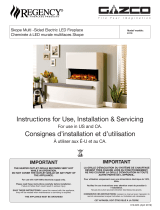
Instructions for Use, Installation & Servicing
For use in US (United States) and CA (Canada).
Consignes d’installation et d’utilisation
À utiliser aux É-U (États-Unis) et au Canada CA.
IMPORTANT
THE HEATER OUTLET GRILLE BECOMES VERY HOT
WHILE IN OPERATION.
DO NOT COVER THE OUTLET GRILLE OR ANY PART OF
THE APPLIANCE.
For use with 120V 60Hz electricity supply only.
Please read these instructions carefully before installation.
Failure to follow them could result in serious injury.
SAVE THESE INSTRUCTIONS: Leave this manual with the appliance,
they will be needed when maintenance or servicing is required.
THIS APPLIANCE MUST BE GROUNDED
IMPORTANT
LA GRILLE D'ÉVACUATION DU SYSTÈME DE CHAUFFAGE
DEVIENT TRÈS CHAUDE LORS DU FONCTIONNEMENT.
NE PAS COUVRIR LA GRILLE D'ÉVACUATION NI TOUTE
AUTRE PARTIE DE L'APPAREIL.
Pour utilisation uniquement avec une alimentation électrique de 120V,
60Hz.
Veuillez lire ces instructions avec attention avant de procéder à
l’installation.
Ne pas les suivre pourrait entraîner des blessures graves.
CONSERVEZ CES INSTRUCTIONS: Laissez ce manuel avec l'appareil, ils
seront nécessaires lorsque l'entretien ou l'entretien est nécessaire.
CET APPAREIL DOIT ÊTRE RELIÉ À LA TERRE
Skope Single Sided - Inset LED Fire
Skope Foyer à LED encastrable à une seule face Skope
Model/ modèle:
E105, E135, E195

2
User Instructions...................................................3
1. Important Information & Health and Safety........................3
2. Operating Instructions........................................................4
3. Maintenance.......................................................................9
Installation Instructions........................................11
Technical Specifications.........................................................11
Appliance Dimensions............................................................11
Installation..............................................................12
1. General...............................................................................12
Copy Of Certification Label...................................................12
2. Fitting the Appliance...........................................................12
3. Stud Installation...................................................................13
4. Wiring Kits...........................................................................14
5. Completing the Installation.................................................15
6. Removing the Exterior Glass..............................................16
7. Fuel Effect...........................................................................17
8. Completion of Assembly......................................................19
Servicing.................................................................20
1. Troubleshooting...................................................................20
2. Servicing Requirements......................................................20
3. Removing the Exterior Glass..............................................21
4. Removing the LED Light Bar..............................................22
5. Removing the Glass Side Panels.......................................22
6. Removing the Fuel Bed......................................................23
7. Replacing the Fuel Bed Effects Spindle.............................23
8. Replacing the Fuel Bed LED Boards..................................24
9. Removing the Interior Glass Screen...................................25
10. Removing the Effects Screen............................................25
11. Replacing the Flame Effects Spindle................................26
12. Replacing the Flame Effect LED Board...........................27
13. Replacing the Fuel Bed Motor..........................................27
14. Replacing the Flame Effect Motor....................................28
15. Replacing the Power Unit.................................................28
16. Replacing the Heater Assembly.......................................29
17. Pairing the Remote Control to the Appliance...................29
18. Resetting the Remote Control..........................................30
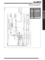
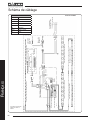
Wiring Diagram......................................................31
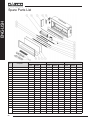
Spare Parts List.....................................................32
Contents
Covering the following models:
Recycle in accordance with Code of
Federal Regulations (CFR), Title 40,
Part 273. This device is classied as
electrical and electronic equipment
As such, it must not be disposed of
with household waste.
At the end of its useful life please
take this product to an appropriate
recycling center or collection point.
You can nd your nearest recycling
drop off point by contacting your
locality’s waste management ofce.
Safety Alert Key:
WARNING! Indicates a hazardous situation
which, if not avoided could result in death or
serious injury.
CAUTION! Indicates a hazardous situation which,
if not avoided, could result in minor or moderate
injury.
ENGLISH
Warranty
This product carries a 1 year warranty.
Please note that all warranties are effective from the date of
purchase.
Full terms and conditions are detailed in the Warranty Statement
on the Regency website www.regency-fire.com. In the event
of any conflict of information the wording on the website shall
prevail.
Important Note: Should any problems be experienced with your
product, claims must first be submitted to the Dealer where
the appliance was purchased from who will offer immediate
assistance or contact Regency on your behalf.
210-183 Skope 105R Inset Electric Fire (41"/1050 mm Fireplace) E105
210-174 Skope 135R Inset Electric Fire (53"/1350 mm Fireplace) E135
210-208 Skope 195R Inset Electric Fire (77"/1950 mm Fireplace) E195
Important : The hand-held transmitter is configured in the
factory with a unique signal code. The hand-held transmitter
is ready for use once the 2 AA batteries are installed.
If the handset loses it signal or needs to be replaced, see
section 17 in the servicing section for details.

3
1. IMPORTANT
INFORMATION AND HEALTH
AND SAFETY
WARNING: Improper installation, adjustment,
alteration, service or maintenance can cause
injury or property damage. Refer to this
manual. For assistance or additional
information, consult a qualified installer.
When using electrical appliances, basic precautions should
always be followed to reduce the risk of fire, electric shock,
and injury to persons, including the following:
1.1 Read all instructions before using this appliance.
1.2 Use this appliance only as described in this
manual. Any other use not recommended by the
manufacturer may cause fire, electric shock, or
injury to persons.
1.3 DO NOT use outdoors.
1.4 NEVER use this appliance in bathrooms, laundry
rooms, or any other location where the appliance
could fall into a bathtub or pool, become damp, or
come in contact with water.
1.5 For residential use only. NOT for commercial use!
Any commercial or public use of this appliance voids
all warranties, and could cause injury.
1.6 This product is not intended to be a primary heat
source. It is for supplemental heat only.
1.7 Do not locate the appliance immediately below a fixed
receptacle outlet.
Electrical Supply Circuit Requirements
Plan the location of the appliance so that it will have
adequate electric power. A 15 AMP, 60Hz circuit is
required for 120V installation. Additional appliances
on the same circuit as this appliance may exceed the
current rating of that circuit. A dedicated circuit is not
required, but is preferred to prevent circuit breaker trips
or fuse failure.
1.8 This appliance must be grounded.
1.9 DO NOT operate any appliance with a damaged cord
or plug or after the appliance malfunctions, has
been dropped or damaged in any manner. Discard
appliance, or return to authorized service facility for
examination and/or repair.
1.10 This appliance is hot when in use. To avoid burns,
DO NOT let bare skin touch hot surfaces. Keep
combustible materials, such as furniture, pillows,
bedding, papers, clothes, and curtains at least 3 feet
(0.9m) from the front of the appliance.
1.11 Extreme caution is necessary when any appliance is
used by or near children or invalids and whenever
the appliance is left operating and unattended.
User Instructions
1.12 DO NOT insert or allow foreign objects to enter any
ventilation or exhaust opening, as this may cause
electric shock or fire, or damage the appliance.
1.13 To prevent a possible fire, DO NOT block air intakes
or exhaust in any manner. Doing so could cause a
fire. DO NOT use on soft surfaces, like a bed, where
openings may become blocked.
1.14 As the appliance has hot and arcing or sparking
parts inside. DO NOT use it in areas where gasoline,
paint, or flammable liquids are used or stored.
1.15 AVOID FIRE! Regularly inspect all air vents to make
sure they are free from dust, lint, or other blockage.
Unplug the unit and clean with a vacuum ONLY. DO
NOT rinse or get wet.
1.16 DO NOT USE this appliance with any solid state
speed control devices.
1.17 Risk of electric shock! DO NOT OPEN! No user-
serviceable parts inside!
1.18 NEVER modify this appliance. Doing so could result
in personal injury or property damage. Modification of
this fireplace completely voids all warranties.
1.19 NEVER leave this appliance unattended. To
disconnect appliance, ALWAYS turn controls to
“OFF” then remove plug from outlet or turn off circuit
when not in use.
1.20 ALWAYS turn this appliance off before unplugging it
from the outlet.
1.21 To prevent a possible fire, do not burn wood or other
materials in this appliance.
1.22 ALWAYS disconnect this unit from the power supply
before performing any assembly or cleaning, or before
relocating the electric fireplace.
1.23 Always use properly grounded, fused and polarized
outlets.
1.24 Always use ground fault protection where required
by electrical code.
1.25 Avoid use of an extension cord because an
extension cord may overheat and cause a fire. If you
have to use an extension cord, the cord should be
N.14 AWG minimum size and rated to not less than
1875watts.
1.26 NEVER plug this appliance into an outlet that is old,
cracked, or has any loose wires or connections.
Plugging this appliance into a faulty outlet could result
in electric arcing within the outlet that could cause the
outlet to overheat or catch fire.
1.27 DO NOT run power cord under carpeting. DO NOT
cover power cord with throw rugs, runners, or similar
coverings. DO NOT route power cord under furniture
or appliances. Arrange power cord away from traffic
area, and where it will not be tripped over.
ENGLISH

4
Under Industry Canada regulations, this radio transmitter
may only operate using an antenna of a type and maximum
(or lesser) gain approved for the transmitter by Industry
Canada. To reduce potential radio interference to other users,
the antenna type and its gain should be so chosen that the
equivalent isotropically radiated power (e.i.r.p.) is not more
than that necessary for successful communication.
This appliance has been approved to the following
standards:
· ICES-003:Issue 6 - Information Technology Equipment
(Including Digital Apparatus) -- Limits and Methods of
Measurement
· ANSI C63.4:2014 - American National Standard for
Methods of Measurement of Radio-Noise Emissions
from Low-Voltage Electrical and Electronic Equipment
in the Range of 9 kHz to 40 GHz
· ANSI C63.10:2013 - American National Standard of
Procedures for Compliance Testing of Unlicensed
Wireless Devices
· 47 CFR Part 15, Subpart B - Radio Frequency
Devices
· 47 CFR Part 15, Subpart C 15.231 - Radio Frequency
Devices
· C22.2 No 46-13 - Electric Air Heaters
· UL 2021 (4th Edition) - Fixed and Location-Dedicated
Electric Room Heaters
· FCC Rules 15C - Federal Communication Commission
· RSP-100 - Labelling Requirements for IC
· RSS-102 Issue 5 (March 2015) - Radio Frequency
(RF) Exposure Compliance of Radiocommunication
Apparatus
· RSS-210 Issue 9 (November 2017) - Licence-Exempt
Radio Apparatus: Category I Equipment
· RSS-Gen Clause 4.6.1 - General Requirements for
Compliance of Radio Apparatus
2. OPERATING
INSTRUCTIONS
WARNING! Do not operate the appliance if it is
damaged or has malfunctioned. If you suspect
the appliance is damaged or has
malfunctioned call a qualified service
technician to inspect the appliance, and
replace any part of the electrical system if
necessary, before reuse.
Do not disconnect the power at the main supply
while the appliance is running. Use the functions on
the remote to turn the fire off and ensure the on/off
switch has been moved to the off position before
disconnecting.
1.28 ALWAYS check your appliance cord and plug
connections with each use!
A. MAKE SURE the plug fits tight in the outlet! Faulty
wall outlet connections or loose plugs can cause the
outlet to overheat.
B. Appliances draw more current than small
appliances. Overheating may occur even if it has not
occurred with the use of other appliances.
C. During use check frequently to see if the plug
outlet is HOT! If the outlet or faceplate is HOT,
discontinue use immediately and have a qualified
electrician inspect and/or replace the faulty outlets.
1.29 SAVE THESE
INSTRUCTIONS.
This device complies with Part 15 of the FCC Rules.
Operation is subject to the following two conditions:
(1) This device may not cause harmful interference,
and
(2) This device must accept any interference received,
including interference that may cause undesired
operation.
Note: This product has been tested and found to comply
with the limits for a Class B digital device, pursuant to Part
15 of the FCC Rules. These limits are designed to provide
reasonable protection against harmful interference in a
residential installation. This product generates, uses, and
can radiate radio frequency energy and, if not installed and
used in accordance with the instructions, may cause harmful
interference to radio communications. However, there is
no guarantee that interference will not occur in a particular
installation. If this product does cause harmful interference
to radio or television reception, which can be determined by
turning the equipment off and on, the user is encouraged to
try to correct the interference by one or more of the following
measures:
—Reorient or relocate the receiving antenna.
—Increase the separation between the equipment and
receiver.
—Connect the equipment into an outlet on a circuit
different from that to which the receiver is connected.
—Consult the dealer or an experienced radio/TV
technician for help.
Please take attention that changes or modification not
expressly approved by the party responsible for compliance
could void the user’s authority to operate the equipment.
This equipment should be installed and operated with a
minimum distance 8" (203 mm) between the radiator and your
body. Refer to page 12 for a copy of the serial decal.
This device complies with Industry Canada licence-
exempt RSS standard(s). Operation is subject to the
following two conditions:
(1) this device may not cause interference, and
(2) this device must accept any interference, including
interference that may cause undesired operation of the
device.
User Instructions
ENGLISH

5
GENERAL
2.1 The appliance can be operated by the remote control
handset or the manual controls which are on the right
hand side of the viewing window.
NOTE: To use both remote and manual
functions the manual on/off switch must be in
‘ON’ position. In order to prevent the product
becoming too hot, there is a 10s delay when
turning on the heater and a 10s delay when
turning off the heater fan.
The manual button controls basic functions, not
a full range of controls. Use the remote hand set
to carry out all functions.
PREPARATION BEFORE USE
Batteries:
2.2 Ensure that the handset batteries are new and inserted
correctly.
2.3 Dispose of old batteries at an appropriate recycling
facility.
LOCATION OF POWER SWITCH
2.4 The main power switch is located on the control panel
located on the right-hand side of the viewing window,
see Section 2a.
2.5 Switch ON (—) before operating either the remote or
manual controls.
2.6 A long beep is heard to indicate the fire is ready for
use.
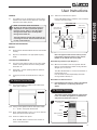
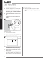
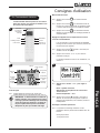
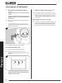
2a. Manual Control Panel
2a.1 The manual controls on appliance are located at the
upper right of appliance.
1
Front View
2a.2 Turning on the appliance with the main power switch
on ‘—‘ position. A long beep will be heard.
2a.3 Press “LIGHTS ON/OFF” to turn on or turn off both the
flame and fuel bed at the same time.
2a.4 There are 3 flame color options:
Press “FLAME” button to select the color of flame or
return to the OFF position.
2a.5 There are 14 fuel bed color options:
Press “FUEL BED” button to select the color of fuel bed
or return to the OFF position.
Main Power
(On/Off) Switch
Fuel bed
setting button
Flame setting
button
All Lights
On/ Off button
Reset Button for
Remote Control
Heater Running
Indicators
2
LAYOUT MAY VARY
Note: The appliance will lose the memory for the
light functions when the switch is set to the Off
Position or the remote runs out of power.
Heater Running Indicators (see Diagram 1)
2a.6 When the fan heater is used in conjunction with the
flame or fuel bed effects the heater running indicators
will light up for 10 seconds.
The LEDs will illuminate for 10 seconds if the flame or
fuel bed effect is On.
If the fan heater is used independently, the heater
running indicators will stay on.
Reset Button for Remote Control
2a.7 If the handset loses signal or needs to be replaced
then, see Section 17 in Servicing Section for
details.
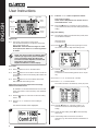
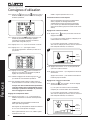
2b. Remote Controls
The remote control should be left on a flat surface
in the room where the appliance is installed and
away from any direct flow of hot air.
Timer in
Normal Mode
Flame
Power
Heating/ Advance
Mode
Temperature Sensor
Convection
Display
Fuel Bed
3
User Instructions
ENGLISH

6
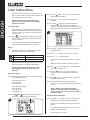
Heating
Period
Battery
Power
Actual Room
Temperature
Timer Mode
Advance
Temperature
Setting
Time and
Day
4
Comfort
Setting
Signal Code
2b.1 The remote control works by radio signal.
The handheld transmitter is configured in the factory
with a unique signal code.
IMPORTANT: If the handset loses signal or needs
to be replaced, see Section 17 in Servicing Section
for details.
NOTE: The remote control has a Battery Status
indicator (top right corner), after an extended
period of displaying empty the LED screen
will cease to function despite the handset still
being able to send commands.
Replace the batteries to restore display.
Turn on/off
2b.2 Press button to turn on the flame effect.
2b.3 Press button to turn off all the functions under the
normal heating control mode including flame effect and
fan heater.
2b.4 Press button to turn off the flame effect under
daily and week timer heating mode.
Week Days/ Time/ Comfort Temperature and change
between Celsius/Fahrenheit
On activation it is recommended that the clock is reset
to the correct time to ensure accuracy of the appliance
operation.
2b.5 Hold the button for 3 seconds to enter the setting
screen.
2b.6 Press the ‘’ or ‘’ button to choose setting to
change.
The selected character will be highlighted.
5
2b.7 Press the ‘+’ or ‘-’ button to adjust the number.
Time: 24-hour system.
Select Comfort temperature from 15-25℃/ 59-77℉.
Celsius/Fahrenheit : ℃/℉.
2b.8 Press the button for 3 seconds or wait 10 seconds
to save and exit the week, time and heating temperature
setting.
Daily Timer Heating
2b.9 The following heating periods have been preset, these
can be altered if desired:
06:00 until 08:00
17:00 until 22:00
2b.10 Press until shows at the upper right corner of
the screen to enter the daily timer heating mode.
6
2b.11 Hold the button for 6 seconds to enter the daily
heating setting.
A maximum of 3 timed heating periods can be set per
day.
2b.12 Press ‘’ or ‘’ to choose hour or minute.
2b.13 Press ‘+’ or ‘-’ to set the number.
The minute increment / decrement by 15min per press.
7
2b.14 Hold the button for 3 seconds or wait for 10
seconds to save and exit the heating time period
setting.
2b.15 Check the timer setting. Press to check the daily
timer mode.
2b.16 If the heating needs to be turned off, it will be
necessary to go back to the Normal Control Mode to it
turn off.
User Instructions
ENGLISH

7
User Instructions
When in Daily Timer Mode switching the appliance
off with the remote will stop the light output. The
heat output will continue according to the timer
settings.
Adjusting the Set Temperature
2b.17 Press the ‘+’ or ‘-’ button to increase or decrease the
temperature on the basis of COMF temperature.
COMF means the actual temperature is the same as
setting.
ECO means the actual temperature is 2℃/4℉ lower
than the setting temperature.
ECO- means 4℃/7℉ lower, COMF+ means 2℃/4℉
higher.
COMF++ means 4℃/7℉ higher.
Adaptive start control
According to room temperature and set-pointed
temperature, the heater will automatically determine
the appropriate time to heat to ensure that it will reach
the set-pointed temperature in the set time (up to 45
minutes prior to the set time).
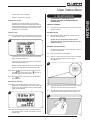
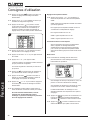
Flame Color Adjustment
2b.18 Press button to enter the flame adjustment
screen.
There are 3 flame color options, indicated by the
number shown in Diagram 7.
There are 6 levels of brightness, including off. This is
indicated by the bar, with the blank bar indicating off,
see Diagram 8.
8
Brightness
Level
Color
Option
2b.19 Press the ‘’ or ‘’ button to cycle through the flame
color options.
2b.20 Press the ‘+’ button to increase the flame brightness.
Press the ‘-’ button to decrease the flame brightness
until off.
Fuel Bed Color Adjustment
2b.21 Press to enter the fuel bed light adjustment
screen.
There are 14 fuel bed color options, indicated by the
number shown in Diagram 8.
There are 6 levels of brightness, including off. This is
indicated by the bar, with the blank bar indicating off,
see Diagram 9.
9
Brightness
Level
Color
Option
2b.22 Press the ‘’ or ‘’ button to cycle through the fuel
bed color options.
2b.23 Press the ‘+’ button to increase the fuel bed brightness.
Press the ‘-’ button to decrease the fuel bed brightness
until off.
Normal Control Mode
2b.24 Normal Control Mode is the default setting.
Alternatively press button until the logo is
shown at the upper right corner of the screen, see
Diagram 10.
10
2b.25 Press the ‘+’ or ‘-’ button to adjust the setting
temperature from 17℃ to 25℃/ 59℉ to 77℉.
2b.26 Press button to turn the heat on/off, ON
or OFF will show at the lower right corner of the
screen, see Diagram 11.
11
Note: It is normal for the fan heater to stop running for
periods of time. This happens if the room temperature
is higher than the temperature set on the control.
ENGLISH

8
User Instructions
The heater indicator will be turned off after 10s if the
flame is switched ON. The heater indicator will stay ON
if only the heating function is used.
When in Normal Control Mode switching the
appliance off with the remote will stop both the
light and heat output.
Count Down Timer
This setting is only in normal heating control mode. It
allows the appliance to be returned to Standby after a
set period of time. The heater must be switched on to
use this function.
2b.27 Press to cycle through the setting from Off and 0.5
hours to 9 hours. Timer logo and remaining time will
show on the screen.
The heater of appliance can be automatically run by
using daily timer and weekly timer on the remote.
Battery
The battery power level is indicated at the top right of
the remote control screen, see Diagram 4.
Battery Full No action required
Battery Half Power Ensure new batteries are available.
Battery Empty Replace batteries immediately
Battery replacement is recommended after 1 year. The
Remote requires two 1.5V alkaline AAA batteries.
Changing the batteries will not affect the Timer
Mode settings, however, the clock may need
adjusting.
Week Timer Heating
2b.28 The following heating periods have been preset, these
can be altered if desired:
From Monday to Friday
06:00 until 08:30
17:00 until 22:00
From Saturday to Sunday
06:30 until 09:30
11:00 until 13:00
17:00 until 22:00
2b.29 Press until shows at the upper right corner of
the screen to enter the week heating mode.
12
2b.30 Hold the button for 6 seconds to enter the week
timer heating mode setting.
2b.31 Press ‘’ or ‘’ to move the cursor (a flashing
underline).
2b.32 Press the button in the corresponding week
position to select (the character is highlighted) or
cancel (the character is displayed normally) the current
setting, the same time period can be selected together.
13
2b.33 Press the ‘’ button to move the cursor to the time
period setting area.
2b.34 Press ‘’ or ‘’ button to choose hour or minute.
2b.35 Press ‘+’ or ‘-’ to set the number.
A maximum of 3 timed heating periods can be set per
day.
Minute increment / decrement by 15min per press.
2b.36 Press to set the heating time for the selected day
and return to the week line.
2b.37 Hold the button for 3 seconds or wait for 10
seconds to save and exit the heating time period
setting.
2b.38 Press ‘’ or ‘’ to check the timer setting for the
week timer heating mode.
2b.39 If the heating needs to be turned off, it will be
necessary to go back to the Normal Control Mode to it
turn off.
When in Weekly Timer Mode switching the
appliance off with the remote will stop the light
output. The heat output will continue according to
the timer settings.
Adjusting the Set Temperature
2b.40 Press the ‘+’ or ‘-’ button to increase or decrease the
temperature on the basis of COMF temperature.
COMF means the actual temperature is the same as
setting.
ECO means the actual temperature is 2℃/ 4℉ lower
than the setting temperature.
ECO- means 4℃/ 7℉ lower.
ENGLISH

9
COMF+ means 2℃/ 4℉ higher.
COMF++ means 4℃/ 7℉ higher.
Adaptive start control
According to room temperature and set-pointed
temperature, the heater will automatically determine
the appropriate time to heat to ensure that it will reach
the set-pointed temperature in the set time (up to 45
minutes prior to the set time).
Advance mode
2b.41 The heating state can be advanced to the next period
is under both the daily and week timer heating mode.
14
If the heater is on in the current period, pressing the
button will turn the heater off.
If the heater is off in the current period, pressing the
button will turn the heater on.
Whether the actual heating will be on/off also depends
on the room temperature and setting temperature.
2b.42 Press to enter the Advance mode under the
daily and week timer heating mode, will show at
the upper right corner of the screen.
2b.43 Press again or timer period ends will exit the
Advance mode.
Window open detecting
2b.44 When the transmitter detects a rapid drop in room
temperature, it will be judged as an open window: the
warning icon will be displayed and the heating will be
turned off automatically.
15
2b.45 After indoor temperature rise or manual intervention
(by operating remote control), it will return to normal
working state.
User Instructions
3. MAINTENANCE
3.1 ALWAYS UNPLUG FROM MAIN SUPPLY
BEFORE CLEANING OR UNDERTAKING ANY
MAINTENANCE.
GENERAL CLEANING
3.2 Only clean the outer casing when it is cold. Do not use
abrasive cleaners.
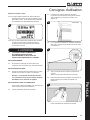
CLEANING GLASS
3.3 Wipe the glass viewing panel with a damp cloth and
buff with a lint free duster.
Caution: Do not use abrasive cleaners on the
glass panel. Do not spray liquids directly onto any
surface of the unit.
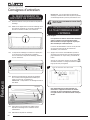
CLEANING THE FUEL EFFECT
To access the fuel effect it will be necessary to remove
the glass viewing panel.
3.4 Ensure the appliance is unplugged.
3.5 There is a clamp at the top of each corner of the glass
viewing panel that secure the glass in place,
see Diagram 15.
15
3.6 Supporting the glass, loosen and remove the 2 clamps.
These can be unscrewed using just finger tips.
3.7 Carefully tip the glass forward and lift out of the lower
tray to remove from the appliance, see Diagram 16.
16
ENGLISH

10
The fuel effect can now be accessed.
3.8 Remove and wash the fuel effect to remove any dust
particles. Alternatively clean with a lint free duster.
Ensure that the effect is dry before replacing.
Replace the fuel effect see Installation Instructions
Section 5 for layout.
3.9 Replace the glass following the instructions in reverse
order.
When replacing the clamps ensure that the tabs on
the clamps locate in the slots on the appliance, see
Diagram 17.
17
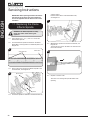
CLEANING AIR INLETS
3.10 Ensure the appliance is unplugged.
3.11 Clean the air inlet and outlet grilles regularly with a soft
cloth or the nozzle of a vacuum cleaner.
Air Outlets
18
Air Inlets
Air Inlets
Top
Front View
Dust build-up can inhibit efficient performance of
the fan and lead to the safety cut-out operating.
3.12 Keep the area around the appliance clean and free of
fluff, dust or pet hair.
3.13 In particular, build-up of dust etc. can occur around the
heater area. Take particular care to keep this area free
from such particles on a regular basis to prevent build-
up.
User Instructions
ENGLISH
BATTERY REPLACEMENT
3.14 When the remote battery is low it must be changed
immediately. Install correct replacement and dispose
of the old battery carefully at an appropriate recycling
facility.

11
Installation Instructions
ENGLISH
A 120V 12.5A 60Hz supply is required
Rated power consumption:
Skope Inset 105R: 1500 Watts
Skope Inset 135R: 1500 Watts
Skope Inset 195R: 1500 Watts
THIS APPLIANCE MUST BE GROUNDED
IMPORTANT: This appliance must be on its own
dedicated circuit with a minimum 15 amp electrical
supply.
FAILURE TO DO SO WILL VOID YOUR WARRANTY.
A 3 prong plug with 72" power lead and a separate
hard wiring kit are supplied.
2 x Remote control handset battery (AAA)
Note: The wiring from the appliance to the breaker must be
supplied by a qualified electrician. This is not supplied with
the appliance
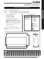
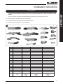
These instructions cover the following models:
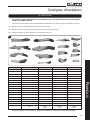
PACKING CHECKLIST
Appliance Description Fixing Kit containing:
Skope Inset 105R:
Skope Inset 135R
Skope Inset 195R
1 x Instruction Manual
1 x Remote Control
2 x AAA Batteries
4 x Fixing Brackets
8 x Screws ST4x8
4 x Screws ST4x12
1 x Wiring Plate
Box 1
Grey Pebble Effect
Clear Pebble Effect
Box 2
Small Glass-Effect Crystals
Large Glass-Effect Crystals
Box 3
1 x Log Set
Box 4
1 x Log Set
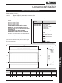
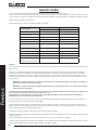
Model
A B C D E F G H
mm in mm in mm in mm in mm in mm in mm in mm in
Inset 105R 1100
43
3
/
16"
380
14
15
/
16
1120
44
560
22
1
/
16
270
10
5
/
8"
57
2
1
/
4"
1132
44
4
/
8"
250
9
7
/
8"
Inset 135R 1400
55
1
/
8"
380
14
15
/
16
1420
55
7
/
8"
560
22
1
/
16
270
10
5
/
8"
57
2
1
/
4"
1432
56
3
/
8"
250
9
7
/
8"
Inset 195R 2000
78
3
/
4"
380 14
15
/
16
2020
79
7
/
8"
560
22
1
/
16
270
10
5
/
8"
57 2
1
/
4"
2032
80
1
/
8"
250
9
7
/
8"
TECHNICAL SPECIFICATION
A E
H
G
C
D
B
F
Note: Box numbers will vary depending on appliance model.
210-183 Skope 105R Inset Electric Fire (41"/1050 mm Fireplace) E105
210-174 Skope 135R Inset Electric Fire (53"/1350 mm Fireplace) E135
210-208 Skope 195R Inset Electric Fire (77"/1950 mm Fireplace) E195

12
Installation Instructions
1. GENERAL
1.1 TOOLS REQUIRED
A Screwdriver, Spirit Level, Saw and Drill will be
needed.
1.2 UNPACKING THE FIREPLACE
WARNING! DO NOT use this appliance if any part
has been exposed to water.
Immediately call a qualified service technician to
inspect and to replace any part of the electrical system
if necessary.
1.3 Open the packaging carefully and remove the
polystyrene.
Remove and discard the plastic bag.
Keep plastic wrapping away from children.
Be responsible when handling the packing materials.
1.4 Check all parts and accessories are removed before
disposing of any packaging.
If necessary keep the original packaging for future
transport and/or storage.
1.5 Test the appliance before installation.
ENGLISH
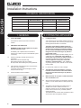
2. FITTING THE APPLIANCE
2.1 Locating the Skope
Your new Skope may be installed virtually anywhere in
your home. However, when choosing a location ensure
that the general instructions are followed.
The heater should ideally be fitted into/onto an
internal flat wall constructed from either stud and
drywall /brick. The fixings provided are intended
for use on brick walls Please ensure that suitable
fixings are used when securing to any hollow or
purpose built cavity.
NOTE: Should the appliance be fitted backing on to an
outside wall, into a Cavity Wall, open chimney or
opening that may be subject to damp and draft, it is
necessary that adequate precautions are taken to
avoid the appliance coming into contact with
moisture or excessive drafts. In such installations,
any existing chimney and/or external air vents should
be fully sealed.
2.2 For best results, install out of direct sunlight.
2.3 The appliance should be installed in a purpose
built stud enclosure. Please ensure that suitable
fixings are used when securing to any hollow or
cavity walls.
2.4 Make sure there are no pipes or cables behind the
area to be drilled or cut.
2.5 Always ensure the appliance is adequately supported
and sits on a firm structure when mounting above floor
level.
2.6 The appliance should ideally be located close to a
suitable main socket to enable connection. An
extension could be run from an existing socket outlet
but this must be carried out by a suitably qualified
electrical engineer.
The electrical socket must be easily accessible to allow
disconnection when the appliance is fitted.
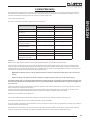
TECHNICAL SPECIFICATION
Control System Technical Data
Main Control Board Remote Receiver Board Remote Control
Hardware RC01-041A01 V2 RF290B V1.2 RF290A-TX V1.3
Software RC01-041A01 V2 - RF290C V06.0.HEX
Frequency - - ASK/OOK 433.92MHz
Maximum Transmit Power - - 10mW

13
2.7 Electrical Supply Circuit Requirements
Plan the location of the appliance so that it will have
adequate electric power. A 15 AMP, 60Hz circuit is
required for 120V installation. Additional appliances
on the same circuit as this appliance may exceed the
current rating of that circuit. A dedicated circuit is not
required, but is preferred to prevent circuit breaker trips
or fuse failure.
2.8 If the power cord is damaged, it must be repaired by
the manufacturer, its authorised service centre or
professional person.
2.9 Ensure that curtains and furniture are not positioned
close to the chosen position, as this would create a
potential fire hazard or block the heater outlet ducts.
WARNING! KEEP ALL COMBUSTIBLE MATERIALS
AT LEAST 3FT (0.9M) FROM THE FRONT OF THE
ELECTRIC FIREPLACE.
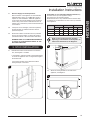
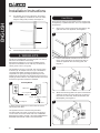
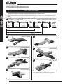
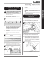
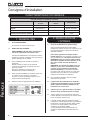
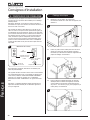
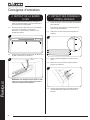
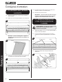
3. STUD INSTALLATION
3.1 Build the stud chase and enclosures to the desired
size, see Diagram 1 and table.
It is essential to include a header at the required height
to ensure the appliance does not support the weight of
the finished wall.
It is important to allow for the finished face when
setting the depth of the frame.
1
ENGLISH
Installation Instructions
Combustible or non-combustible building materials may
be used to finish up to the appliance casing.
The product is a zero clearance design.
Ensure that the stud or any materials used to seal the cavity
(if required) do not obstruct the air vents on the top and sides
of the appliance.
Model W D H
mm in mm in mm in
105R 1138
44
3
/
4"
270
10
5
/
8"
564
22
3
/
16
135R 1438
56
5
/
8"
270
10
5
/
8"
564
22
3
/
16
195R 2038
80
1
/
4"
270
10
5
/
8"
564
22
3
/
16
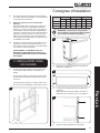
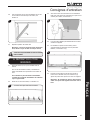
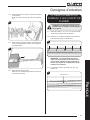
NOTE: 2 sets of holes have been provided
depending on the thickness of the drywall to be
used for the desired finish, see Diagram 2.
2
1
1
2
2
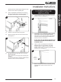
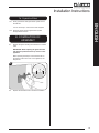
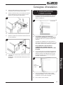
3.2 Attach the 4 fixing brackets to the sides of the
appliance, see Diagram 3.
3

14
3.3 The fireplace can now be positioned in the opening.
Level the appliance, and attach the unit to the frame
using the nailing holes provided, see Diagram 4.
4
3.4 Connect the power cable to the appliance.
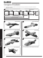
4. WIRING KITS
The Skope is supplied with a 3 prong plug with a 72" lead, it
will need to be modified for hard wiring.
Note: Must be plugged into a 3 prong receptacle which is
exposed and accessible. Do not under any circumstances,
cut the ground on the 3 prong plug.
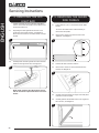
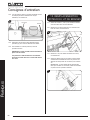
This appliance is for use on 120 Volts. The cord has a plug
as show in (A). An adapter as shown in (C) is available for
connecting three-blade grounding type plugs to two slot
receptacles. The green grounding lug extending from the
adapter must be connected to a permanent ground such as a
properly grounded outlet box. The adapter should not be used
if a three-slot grounded receptacle is available.
Grounding Methods
A
B
Cover of grounded
outlet box
Metal Screw
Grounding Pin
Adapter - Not allowed in Canada
Grounding means
C
5
To disconnect the appliance, turn the controls to off, then
remove plug from outlet.
This appliance must be connected and grounded in
accordance with local codes, if hard wired. In the absence
of local codes, the use the current CSA C22.1 CANADIAN
ELECTRICAL CODE in Canada or the current ANSI/NFPA 70
NATIONAL ELECTRICAL CODE in the United States.
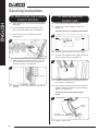
Hard Wiring
Note: The hard wiring from the appliance to the breaker must
be supplied by a qualified electrician. This is not supplied with
the appliance.
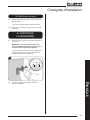
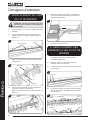
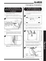
4.1 Remove the 2 screws securing the wiring plate on the
right hand side of the appliance, see Diagram 6.
6
4.2 Insert a small flathead screwdriver into the holes on
the top of the wiring block and press down firmly to
detach the appliance wires from wiring plate, see
Diagram 7.
7
Blue
Red
Yellow/
Green
4.3 Attach the hard wiring plate to the power unit inside the
appliance ensuring the correct wires are connected to
the power block Live Red), Earth (Green/Yellow) and
Neutral (Blue), see Diagram 8.
8
Blue
Red
Yellow/Green
Installation Instructions
ENGLISH

15
Installation Instructions
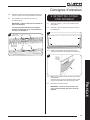
Feed the hard wire cable through the large hole in the
plate and secure with the supplied gland.
4.4 Insert a small flathead screwdriver into the holes on
the top of the wiring block to open the connectors for
Live (Black), Earth (Green) and Neutral (White).
9
White
Blue
Red
Green
Black
Yellow/Green
4.5 Insert the correct wires into the wiring block.
4.6 Replace the wiring plate and secure with the screws,
see Diagram 10.
10
4.7 The other end of the power cable can now be hard
wired into the main.
NOTE: Isolate the power supply when completing the
installation.
The breaker should also be marked to indicate electric
fireplace for ease of serving this appliance.
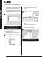
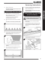
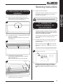
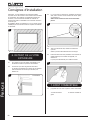
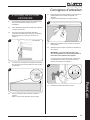
5. COMPLETING THE
INSTALLATION
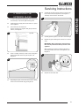
5.1 The decorative trim is held on by magnets. Pull gently
forward to remove, see Diagram 11.
11
Top View
5.2 Combustible or non-combustible building materials
may be used to finish up to the fireplace opening.
The product is a zero clearance design. Any insulation
and vapor barrier should be placed a minimum of 2”
(51mm) from the top of the firebox.
DO NOT PACK THE VOID AROUND OR ABOVE THE
APPLIANCE WITH INSULATION MATERIALS SUCH
AS MINERAL WOOL.
5.3 There is a return surrounding the decorative trim
attached to the front of the appliance. This allows
suitable boarding to be taken up to the edge and
finished off with an even
3
/
16
" (5mm) gap around of the
decorative trim, see Diagram 12.
12
Return;
Board up to
this edge
5.4 With the decorative trim removed, fit suitable boarding
to the wall above, below and to the sides of the
appliance.
ENGLISH

16
Installation Instructions
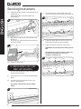
5.5 Finish the chase as desired.
Note: All finished facing material should butt up cleanly
to the flanges around the firebox opening. Rough
edges will be visible from the front view. To maintain
a clean finished edge – it is recommended to install
the combustible facing material with the finished edge
against the fireplace. Alternatively, you can use J style
trim or metal corner bead to cover cut edges of the
facing material.
13
Floor
6. REMOVING THE
EXTERIOR GLASS
6.1 To place the fuel effect it will be necessary to remove
the exterior glass panel.
6.2 First remove the decorative trim.
The trim is held on by magnets. Pull gently forward to
remove, see Diagram 14.
14
Top View
6.3 There is a clamp at the top of each corner of the glass
viewing panel that secure the glass in place, see
Diagram 15.
Take care to support the glass when removing
clamps.
15
6.4 Supporting the glass, loosen and remove the 2
clamps.
These can be unscrewed using just finger tips.
6.5 Carefully tip the glass forward and lift out of the lower
tray to remove from the appliance, see Diagram 16.
The clamp can be used to aid removal.
16
7. FUEL EFFECT
7.1 The appliance is supplied with 2 fuel effect options:
7a. Log Effect. 7b. Crystal Ice Effect.
ENGLISH

17
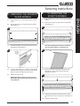
7a. Log Effect
LOGS MUST BE POSITIONED ACCORDING TO THE FOLLOWING INSTRUCTIONS TO GIVE THE CORRECT FLAME
EFFECT.
The logs for the fuel bed are NOT individually labelled, the numbers are for reference information only.
7a.1 Evenly spread the clear pebble effect across the fuel bed.
7a.2 Randomly space the grey pebble effect throughout the fuel bed.
7a.3 Identify the logs using Diagram 17 and the table below.
17
1
5 9
13
14
15
16
17
10
11
12
6
7
8
2
3
4
Log Size Skope Inset 105R Skope Inset 135R Skope Inset 195R
1 Large
2 Large
3 Large
4 Large
5 Large
6 Large
7 Large
8 Medium
9 Medium
10 Medium
11 Small
12 Small
13 Small
14 Small
15 Small
16 Small
17 Small
Total
3 Small
3 Medium
3 Large
5 Small
3 Medium
4 Large
7 Small
3 Medium
7 Large
Installation Instructions
ENGLISH

18
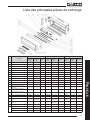
105R/ 135R/ 195R Layout
Please refer to Diagram 17 and table on page 16 to identify the logs for specific models.
7a.4 The logs are positioned in pairs. Working from left to right, place the logs onto the stone fuel effect following the layouts
below:
18
Diagram 19
Logs 6 & 8
Diagram 20
Logs 7 & 13
Diagram 22
Logs 9 & 10
Diagram 24
Logs 1 & 4
Diagram 21
Logs 2 & 17
Diagram 23
Logs 5 & 12
14
16
15
Diagram 25
Logs 3 & 11
See Diagram 19 - 25 for details of log pairs
Dotted Lines show the layouts for the different models
195R Layout
135R Layout
105R Layout
Installation Instructions
ENGLISH
19
6
8
USED ON ALL MODELS
20
13
7
USED ON ALL MODELS
21
17
2
USED ON ALL MODELS
22
9
10
USED ON ALL MODELS
23
12
5
USED ON 135R & 195R ONLY
24
1
4
USED ON 195R ONLY
25
11
3
USED ON 195R ONLY
7a.5 If desired the Crystal Ice Effect can be placed in
between the log layout, see Section 5b.

19
Installation Instructions
7b. Crystal Ice Effect
7b.1 Evenly spread the small glass-effect crystals across
the fuel bed.
It is not necessary to use all of the effect supplied.
7b.2 Randomly space the large glass-effect crystals
throughout the fuel bed.
8. COMPLETION OF
ASSEMBLY
8.1 Replace the glass following the instructions in reverse
order.
IMPORTANT: When replacing the glass the black
tabs must be positioned at the top corners of the
appliance.
When replacing the clamps ensure that the tabs on
the clamps locate in the slots on the appliance, see
Diagram 26.
26
8.2 Replace the decorative trim to finish the installation.
ENGLISH

20
1. TROUBLESHOOTING
No illumination or uneven lighting:
1.1 Check the circuit breaker and reset if necessary.
If the appliance does still not work, check the
receptacle by plugging in a working appliance. If this
too fails to operate, call in a competent electrician to
check the receptacle.
1.2 One or more of the LED boards will need replacing.
This must be undertaken by a suitably qualified person
(see Servicing Requirements).
Illumination but no heat:
1.3 The safety cut-out has operated to protect against
overheating (see User Instructions, Section 2). Ensure
the air inlet and outlet grilles are free of dust or any
other obstruction.
1.4 The thermostat control may be set too low. Increase
the setting by pressing the thermostat button on the
remote control until the heater turns on.
Remote control fails to work:
1.5 Check that the batteries are new and correctly fitted.
Replace if necessary.
1.6 Ensure that the handset is pointed towards the fire.
2. SERVICING
REQUIREMENTS
DURING SERVICING OF THIS APPLIANCE IT MAY
BE NECESSARY TO CUT CABLE TIES IN ORDER
TO ACCESS AND REMOVE SOME OF THE PARTS.
THESE MUST BE REPLACED WHEN
REASSEMBLING THE APPLIANCE.
CAUTION: The Effects Spindles are sharp, please
use caution when servicing this appliance.
NOTE: Due to the number of models covered
within this instruction manual the number
of screws that need to be removed during
servicing may vary.
PLEASE ENSURE NO WIRES ARE TRAPPED.
THIS APPLIANCE MUST ONLY BE SERVICED BY A
SUITABLY QUALIFIED PERSON.
ENGLISH
Servicing Instructions
BEFORE UNDERTAKING ANY WORK ON THE
APPLIANCE: SWITCH OFF THE APPLIANCE AND
ISOLATE THE POWER SUPPLY ENSURING THERE IS
NO POWER TO THE APPLIANCE.
2.1 CAUTION: Wait for at least 10 minutes until the
appliance has cooled down.
2.2 Remote Handset Battery Replacement
Replace with 2 AAA batteries. Make sure the batteries
are installed correctly in the remote control.
2.3 Maintenance of Motors
The motor used on the flame effect is pre-lubricated for
extended bearing life and requires no further
lubrication. However, periodic cleaning/vacuuming of
the heater unit is recommended.
2.4 Resetting the Thermal Cutout Switch
The appliance is fitted with an Electronic Safety Control
(E.S.). This is a safety device which switches off the
fire if, the appliance overheats for any reason e.g.
when covered.
If the heater stops operating while the flame effect
continues normally, this indicates that the E.S. Control
is in operation.
The E.S. Control can only be re-set after the appliance
has cooled down.
To re-set the E.S:
Switch off the appliance (Manual On/Off switch) and
leave for approximately 120 minutes.
Remove any obstruction to the fan heater outlet or
other internal parts.
Switch on appliance and the E.S. Control will re-set.
Ensure that the appliance is functioning correctly. If the
E.S. Control operates again, the appliance should be
checked by a qualified Electrician.
La page charge ...
La page charge ...
La page charge ...
La page charge ...
La page charge ...
La page charge ...
La page charge ...
La page charge ...
La page charge ...
La page charge ...
La page charge ...
La page charge ...
La page charge ...
La page charge ...
La page charge ...
La page charge ...
La page charge ...
La page charge ...
La page charge ...
La page charge ...
La page charge ...
La page charge ...
La page charge ...
La page charge ...
La page charge ...
La page charge ...
La page charge ...
La page charge ...
La page charge ...
La page charge ...
La page charge ...
La page charge ...
La page charge ...
La page charge ...
La page charge ...
La page charge ...
La page charge ...
La page charge ...
La page charge ...
La page charge ...
La page charge ...
La page charge ...
La page charge ...
La page charge ...
La page charge ...
La page charge ...
La page charge ...
La page charge ...
La page charge ...
La page charge ...
La page charge ...
La page charge ...
-
 1
1
-
 2
2
-
 3
3
-
 4
4
-
 5
5
-
 6
6
-
 7
7
-
 8
8
-
 9
9
-
 10
10
-
 11
11
-
 12
12
-
 13
13
-
 14
14
-
 15
15
-
 16
16
-
 17
17
-
 18
18
-
 19
19
-
 20
20
-
 21
21
-
 22
22
-
 23
23
-
 24
24
-
 25
25
-
 26
26
-
 27
27
-
 28
28
-
 29
29
-
 30
30
-
 31
31
-
 32
32
-
 33
33
-
 34
34
-
 35
35
-
 36
36
-
 37
37
-
 38
38
-
 39
39
-
 40
40
-
 41
41
-
 42
42
-
 43
43
-
 44
44
-
 45
45
-
 46
46
-
 47
47
-
 48
48
-
 49
49
-
 50
50
-
 51
51
-
 52
52
-
 53
53
-
 54
54
-
 55
55
-
 56
56
-
 57
57
-
 58
58
-
 59
59
-
 60
60
-
 61
61
-
 62
62
-
 63
63
-
 64
64
-
 65
65
-
 66
66
-
 67
67
-
 68
68
-
 69
69
-
 70
70
-
 71
71
-
 72
72


Regency E105 Le manuel du propriétaire
- Catégorie
- Cheminées
- Taper
- Le manuel du propriétaire
- Ce manuel convient également à
dans d''autres langues
- English: Regency E105 Owner's manual
Documents connexes
Autres documents
-
Stovax eReflex 70W Guide d'installation
-
-
-
-
-
GAZCO Arosa & Cerreto 140 LED Electric Stove Manuel utilisateur
-
-
-
-