Tetra Stick LED Signage Guide d'installation
- Taper
- Guide d'installation

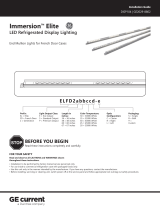
Stick
Fluorescent Box Sign Retrot
LED Lighting System
Installation Guide
SIGN220 | A-1001149
RETROFIT SIGN CONVERSION LED KIT FOR USE ONLY IN
ACCORDANCE WITH KIT INSTRUCTIONS.
KIT IS COMPLETE ONLY WHEN ALL PARTS REQUIRED BY
THE INSTRUCTIONS ARE PRESENT.
TROUSSE DE CONVERSION À DEL POUR LA
MODERNISATION DES ENSEIGNES
À UTILISER CONFORMÉMENT AU GUIDE D’INSTALLATION.
Electrical Requirements
• Limited to use in dry and damp locations.
• The grounding and bonding of the LED Driver shall be done
in accordance with National Electric Code (NEC) Article 600.
• Follow all National Electric Codes (NEC) and local codes.
• These products are only suitable for connection to a circuit
from a Class 2 power source.
• These products have not been evaluated for use when
connected to a power source that does not comply with
Class 2 voltage and energy limited supplies.
Save These Instructions
Use only in the manner intended by the manufacturer. If
you have any questions, contact the manufacturer.
WARNING / AVERTISSEMENT
RISK OF ELECTRIC SHOCK
∙ Turn power off before inspection, installation or removal.
∙ Properly ground power supply enclosure.
RISK OF FIRE
∙ Use only UL approved wire for input/output connections.
Minimum size 18 AWG (0.82mm2)
∙ Follow all NEC and local codes.
∙ Not to be submerged or used in a marine environment.
RISK OF FIRE OR ELECTRIC SHOCK
∙ LED Retrofit Kit installation requires knowledge of
sign electrical systems. If not qualified, do not attempt
installation. Contact a qualified electrician.
∙ Install this kit only in host signs that have been identified in
the installation instructions and where the input rating of the
retrofit kit does not exceed the input rating of the sign.
∙ Installation of this LED retrofit kit may involve drilling or
punching of holes into the structure of the sign. Check for
enclosed wiring and components to avoid damage to wiring
and electrical parts.
∙ Do not make or alter any open holes in an enclosure of
wiring or electrical components during kit installation.
RISQUES DE DÉCHARGES ÉLECTRIQUES
∙ Coupez l’alimentation avant l’inspection, l’installation ou le déplacement.
∙ Assurez-vous de correctement mettre à terre l’alimentation électrique.
RISQUES D’INCENDIE
∙ N’utilisez que des fils approuvés par UL pour les entrées/sorties de connexion.
Taille minimum 18 AWG (0.82mm2)
∙ Respectez tous les codes NEC et codes locaux.
∙ Ne pas submerger ou installer dans un environnement marin.
RISQUE D’INCENDIE OU DE CHOC ÉLECTRIQUE
∙ L’installation de l’équipement de remplacement DEL exige Ia connaissance des
systèmes électriques pour enseignes. Si non qualifié, ne tentez pas d’installation.
Veuillez contacter un électricien qualifié.
∙ Risque d’incendie ou de choc Électrique. Installez cet ensemble seulement dans des
enseignes hôtes qui ont été identifiés dans les instructions d’installation et dont la
capacité d’entrée de l’ensemble ne dépasse pas la capacité d’entrée de l’enseigne.
∙ L’installation de cet équipement de remplacement DEL peut impliquer le perçage
ou le poinçonnage de trous dans la structure du panneau Vérifiez le câblage et
les composants inclus pour éviter d’endommager le câblage et les composants
électriques.
∙ Ne pas faire ou modifier les trous ouverts dans une enceinte de câblage
ou de composants électriques pendant l’installation de cet équipement de
remplacement DEL.
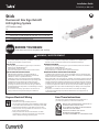
Prepare Electrical Wiring
2424
Volt
(GETSaabbcccdde)*
*key
aa PM = PowerMax or PH = PowerMax High Output
bb SS = Single Sided or DS = Double Sided
ccc 018=18’’; 024=24’’; 030=30’’; 036=36’’; 042=42’’; 048=48’’; 060=60’’;
064=64’’; 072=72’’; 084=84’’; 096=96’’; 108=108’’; 117=117’’; 120=120’’
dd 71 = 7100K CCT; 57 = 5700K CCT
e A=3’ Whip Length or B=6’ Whip Length
BEFORE YOU BEGIN
Read these instructions completely and carefully.

TC Measure Point
Tetra® Stick Installation Guide
2
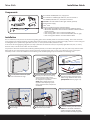
Installation
Turn off power and remove panel
from fluorescent box sign. Read the product labels to determine
Tetra Stick length required to span
width of sign based on table in the
Specications section (pages 4-5).
Old Fluorescent
tube
Remove old
components F48T12HO
or F48T8HO
Remove old fluorescent tubes, ballast
and wiring. DO NOT remove existing
fluorescent lamp holders. Inspect
existing sockets and replace as needed.
De-energize the lamp holders.
NOTE:
Follow all federal and local
regulations when disposing of neon
tubing, uorescent tubes, transformers
and ballasts.
Prior to installation, survey the site for information regarding power and accessibility inside and outside the building. Ensure that the branch
circuit supplying the existing transformer or ballast will be within the voltage ratings of the new LED power supply, and have a current rating not
exceeding 20A, or that permitted by applicable local, state, or country electrical codes (whichever is less).
If removal of the existing lighting equipment (see Step 2) eliminates the disconnect switch, as required by applicable local, state, or country
electrical codes; a new disconnect switch must be installed.
If required, the disconnect switch shall be installed by qualified personnel, in accordance with applicable local, state, and country electrical codes.
Repair and seal any unused openings in the electrical enclosure. Openings greater than 12.7-mm (1/2-in) diameter require a metal patch
secured by screws or rivets and caulked with non-hardening caulk. Smaller openings may be sealed with non-hardening caulk.
GETSAABBCCC71-6-1
Tetra Stick
UL certified 18 AWG (0.82 mm2) supply wire
UL certified 22-14 AWG (0.33-2.08 mm2) wire connectors or
22-18 AWG (0.33-0.82 mm2) inline/IDC connectors
93020091 LFL-LED Sockets LineFit Light Sockets (optional)
24 Volt Power Supply
Tetra® Stick
Electrical grade RTV silicone. Examples below:
• Momentive RTV 6700 Series Silicone Rubber Adhesive Sealant
• Momentive White Blanc RTV 162 Silicone Rubber Adhesive Sealant-
Electrical Grade
• Dow Corning 3140 - Non-Corrosive Flowable (clear)
• Dow Corning 3145 - Non-Corrosive Nonflowable (clear or gray)
• Dow Corning RTV 748 Non-Corrosive Sealant-White
Push Tetra Stick into existing
fluorescent lamp holders. Continue installing Tetra Stick fixtures.
NOTE: For horizontal installations
greater than 6ft in length, the Tetra
Stick(s) should be centrally supported.
Orient Tetra Stick so LEDs are facing
front of sign.
See Note about support
LEDs face
front of sign
Existing socket should
be push-in double
contact lamp holder
1
2
3
4
5
6
Components
123
4
5
6
1
4
2
5
3
6

+
+
Tetra® Stick Installation Guide
3
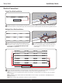
Connect the red wire (+) of the Tetra Stick to the red wire (+) of the power supply. Connect the black wire (-) of the Tetra Stick to
the black or blue wire (-) of the power supply. Seal all connections that could be exposed to water with electrical grade RTV silicone
Electrical Connections
Single Tetra Stick Installation
Power Supply
Add up total number of Tetra Sticks to determine the
appropriate number of 24VDC Class 2 Tetra LED drivers
to use based on the Specications Charts for Tetra
Stick chosen (see pages 4-5).
Multiple Tetra Stick Installation
Connect the red wire (+) of the Tetra Stick to the red
wire (+) of the power supply. Connect the black wire (-)
of the Tetra Stick to the black or blue wire (-) of the
power supply.
AC line GEPS24-180
Connect Tetra Stick using twist-on wire connectors or in-line (IDC) connectors. Join black wires together and red wires
together. Seal all connections that could be exposed to water with electrical grade RTV silicone.
NOTE: Make sure not to exceed LED driver power limits (see Step 1). Drawing above is for reference only; your lighting
layout may differ.
NOTE: All drivers except GEPS24-180U and GEPS24-300U must be enclosed or provided with a GEPSJB60 LED driver
extended enclosure.
NOTE: Refer to Power Supply Installation Guide for AC driver installation.
Power supply To Tetra Sticks
Red (+)
Red (+) Black (-)
Black or blue (-)
Power supply To Tetra Sticks
Red (+)
Red (+) Black (-)
Black or blue (-)
1
1
3
2

Tetra® Stick Installation Guide
4
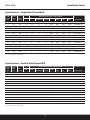
T-12
Length
(in)
Actual
Length
(in)
Watts
per Stick
Sticks per Power Supply - Total (per Bank)
Part Number
60W 80W 100W
GLX/UVSI/NA
100W
GLX2/TT 180W 200W
GLX2
300W
GL
300W
GLX2
18 15.91 1.70 28 38 47 51 86(43) 102(51) 141(47) 153(51) GETSPMSS18**#1
24 21.91 2.50 19 26 32 34 58(29) 68(34) 96(32) 102(34) GETSPMSS24**#1
30 27.91 2.50 19 26 32 34 58(29) 68(34) 96(32) 102(34) GETSPMSS30**#1
36 33.91 3.40 14 19 24 25 42(21) 50(25) 72(24) 75(25) GETSPMSS36**#1
42 39.91 4.20 12 15 19 20 34(17) 40(20) 57(19) 60(20) GETSPMSS42**#1
48 45.91 5.00 10 13 16 17 30(15) 34(17) 48(16) 51(17) GETSPMSS48**#1
60 57.91 5.90 8 11 14 14 24(12) 28(14) 42(14) 42(14) GETSPMSS60**#1
64 61.91 6.70 7 10 12 12 22(11) 24(12) 36(12) 36(12) GETSPMSS64**#1
72 69.91 7.60 6 8 11 11 20(10) 22(11) 33(11) 33(11) GETSPMSS72**#1
84 81.91 8.40 6 8 10 10 18(9) 20(10) 30(10) 30(10) GETSPMSS84**#1
96 93.91 10.10 5 6 8 8 14(7) 16(8) 24(8) 24(8) GETSPMSS96**#1
108 105.91 10.90 4 6 7 7 14(7) 14(7) 21(7) 21(7) GETSPMSS108**#1
117 114.91 11.80 4 5 7 7 12(6) 14(7) 21(7) 21(7) GETSPMSS117**#1
120 117.91 12.60 4 5 6 6 12(6) 12(6) 18(6) 18(6) GETSPMSS120**#1
T-12
Length
(in)
Actual
Length
(in)
Watts
per Stick
Sticks per Power Supply - Total (per Bank)
Part Number
60W 80W 100W
GLX/UVSI/NA
100W
GLX2/TT 180W 200W
GLX2
300W
GL
300W
GLX2
18 15.91 3.40 14 19 24 25 42(21) 50(25) 72(24) 75(25) GETSPMDS18**#1
24 21.91 5.00 10 13 16 17 30(15) 34(17) 48(16) 51(17) GETSPMDS24**#1
30 27.91 5.00 10 13 16 17 30(15) 34(17) 48(16) 51(17) GETSPMDS30**#1
36 33.91 6.80 7 9 12 12 22(11) 2(12) 36(12) 36(12) GETSPMDS36**#1
42 39.91 8.40 6 8 10 10 18(9) 20(10) 30(10) 30(10) GETSPMDS42**#1
48 45.91 10.00 5 6 8 8 14(7) 16(8) 24(8) 24(8) GETSPMDS48**#1
60 57.91 11.80 4 5 7 7 12(6) 14(7) 21(7) 21(7) GETSPMDS60**#1
64 61.91 13.40 4 5 6 6 10(5) 12(6) 18(6) 18(6) GETSPMDS64**#1
72 69.91 15.20 3 4 5 5 10(5) 10(5) 15(5) 15(5) GETSPMDS72**#1
84 81.91 16.80 3 4 5 5 8(4) 10(5) 15(5) 15(5) GETSPMDS84**#1
96 93.91 20.20 2 3 4 4 6(3) 8(4) 12(4) 12(4) GETSPMDS96**#1
108 105.91 21.80 2 3 3 3 6(3) 6(3) 9(3) 9(3) GETSPMDS108**#1
117 114.91 23.60 2 2 3 3 6(3) 6(3) 9(3) 9(3) GETSPMDS117**#1
120 117.91 25.20 2 2 3 3 6(3) 6(3) 9(3) 9(3) GETSPMDS120**#1
Specifications – Single Sided PowerMAX
Specifications – Double Sided PowerMAX
**71 = 7100K CCT; 57 = 5700K CCT
# A = 3 foot whip; B = 6 foot whip
**71 = 7100K CCT; 57 = 5700K CCT
# A = 3 foot whip; B = 6 foot whip

Tetra® Stick Installation Guide
5
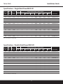
Specifications – Single Sided PowerMAX HO
Specifications – Double Sided PowerMAX HO
T-12
Length
(in)
Actual
Length
(in)
Watts per
Stick
Sticks per Power Supply - Total (per Bank)
Part Number
60W 80W 100W
GLX/UVSI/NA
100W
GLX2/TT 180W 200W
GLX2
300W
GL
300W
GLX2
18 15.91 2.40 20 26 33 36 58(29) 72(36) 99(33) 108(36) GETSPHSS18**#1
24 21.91 3.60 13 17 22 24 40(20) 48(24) 66(22) 72(24) GETSPHSS24**#1
30 27.91 3.60 13 17 22 24 40(20) 48(24) 66(22) 72(24) GETSPHSS30**#1
36 33.91 4.80 10 13 16 18 30(15) 36(18) 48(16) 54(18) GETSPHSS36**#1
42 39.91 6.00 8 10 13 14 24(12) 28(14) 39(13) 42(14) GETSPHSS42**#1
48 45.91 7.20 7 9 11 12 20(10) 24(12) 33(11) 36(12) GETSPHSS48**#1
60 57.91 8.40 6 7 9 10 18(8) 20(10) 27(9) 30(10) GETSPHSS60**#1
64 61.91 9.60 5 7 8 9 14(7) 18(9) 24(8) 27(9) GETSPHSS64**#1
72 69.91 10.80 4 6 7 8 14(7) 16(8) 21(7) 24(8) GETSPHSS72**#1
84 81.91 12.00 4 5 7 7 12(6) 14(7) 21(7) 21(7) GETSPHSS84**#1
96 93.91 14.40 3 4 6 6 10(5) 12(6) 18(6) 18(6) GETSPHSS96**#1
108 105.91 15.60 3 4 5 5 10(5) 10(5) 15(5) 15(5) GETSPHSS108**#1
117 114.91 16.80 3 4 5 5 8(4) 10(5) 15(5) 15(5) GETSPHSS117**#1
120 117.91 18.00 3 3 4 4 8(4) 8(4) 12(4) 12(4) GETSPMSS120**#1
T-12
Length
(in)
Actual
Length
(in)
Watts per
Stick
Sticks per Power Supply - Total (per Bank)
Part Number
60W 80W 100W
GLX/UVSI/NA
100W
GLX2/TT 180W 200W
GLX2
300W
GL
300W
GLX2
18 15.91 4.80 10 13 16 18 30(15) 36(18) 48(16) 54(18) GETSPHDS18**#1
24 21.91 7.20 7 9 11 12 20(10) 24(12) 33(11) 36(12) GETSPHDS24**#1
30 27.91 7.20 7 9 11 12 20(10) 24(12) 33(11) 36(12) GETSPHDS30**#1
36 33.91 9.60 5 7 8 9 14(7) 18(9) 24(8) 27(9) GETSPHDS36**#1
42 39.91 12.00 4 5 7 7 12(6) 14(7) 21(7) 21(7) GETSPHDS42**#1
48 45.91 14.40 3 4 5 6 10(5) 12(6) 15(5) 18(6) GETSPHDS48**#1
60 57.91 16.80 3 4 5 5 8(4) 10(5) 15(5) 15(5) GETSPHDS60**#1
64 61.91 19.20 2 3 4 4 8(4) 8(4) 12(4) 12(4) GETSPHDS64**#1
72 69.91 21.60 2 3 4 4 6(3) 8(4) 12(4) 12(4) GETSPHDS72**#1
84 81.91 24.00 2 2 3 3 6(3) 6(3) 9(3) 9(3) GETSPHDS84**#1
96 93.91 28.80 2 2 3 3 4(2) 6(3) 9(3) 9(3) GETSPHDS96**#1
108 105.91 31.20 2 2 2 2 4(2) 4(2) 6(2) 6(2) GETSPHDS108**#1
117 114.91 33.60 1 2 2 2 4(2) 4(2) 6(2) 6(2) GETSPHDS117**#1
120 117.91 36.00 1 1 2 2 4(2) 4(2) 6(2) 6(2) GETSPMDS120**#1
**71 = 7100K CCT; 57 = 5700K CCT
# A = 3 foot whip; B = 6 foot whip
**71 = 7100K CCT; 57 = 5700K CCT
# A = 3 foot whip; B = 6 foot whip

Tetra® Stick Installation Guide
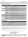
Wattage Power Supply Long Description
60W
GELP24-60U-GL Power Supply (24VDC / 60W), Input Voltage: 108-305VAC; Damp Rated; Remote or
Raceway; 1 Output Bank; Class 2
GEPS24D-60U-GLX 0-10V Dimming Power Supply (24VDC/60W), Input Voltage: 108-305VAC; Damp Rated;
Remote or Raceway; 1 Output Bank; Class 2
80W
GEPS24D-80U 0-10V Dimming Power Supply (24VDC/80W), Input Voltage: 90-305VAC; Damp Rated;
Remote or Raceway; 1 Output Bank; Class 2
GEPS24W-80 Power Supply (24VDC/80W), Input Voltage: 90-264VAC; Wet Location Rated;
1 Output Bank; Class 2
100W
GEPS24-100U-GLX
USVI-100024FBA
USVI-100024FE
Power Supply (24VDC / 96W), Input Voltage: 108-305VAC; Damp Rated;
Remote or Raceway; 1 Output Bank; Class 2
GEPS24D-100U-NA 0-10V Dimming Power Supply (24VDC/100W), Input Voltage: 108-305VAC; Damp Rated;
Remote or Raceway; 1 Output Bank; Class 2
GEPS24-100U-GLX2/TT Power Supply (24VDC/100W), Input Voltage: 108-305VAC; Damp Rated;
Remote or Raceway; 1 Output Bank; Class 2
180W GEPS24-180U Power Supply (24VDC/180W), Input Voltage: 90-305VAC; Damp Rated;
Integrated junction box, Remote or Raceway; 2 Output Banks of 90W each; Class 2
200W GEPS24-200U-GLX2 Power Supply (24VDC/200W), Input Voltage: 108-305VAC; Damp Rated;
Integrated junction box, Remote or Raceway; 2 Output Banks of 100W each; Class 2
300W
GEPS24-300U-GL Power Supply (24VDC/288W), Input Voltage:108-305VAC; Damp Rated;
Integrated junction box, Remote or Raceway; 3 Output Bank; Class 2
GEPS24-300U-GLX2 Power Supply (24VDC/300W), Input Voltage:108-305VAC; Damp Rated;
Integrated junction box, Remote or Raceway; 3 Output Banks of 100W each; Class 2
Power Supply Specifications
Troubleshooting
This product is intended solely for the use of non-residential signage lighting and is not intended for use in any other applications.
Conforms to the following standards:
III
This device complies with part 15 of the FCC Rules. Operation is subject to the following two conditions: (1) This device may not cause harmful interference,
and (2) this device must accept any interference received, including interference that may cause undesired operation.
Note: This equipment has been tested and found to comply with the limits for a Class A digital device, pursuant to part 15 of the FCC Rules. These limits
are designed to provide reasonable protection against harmful interference when the equipment is operated in a commercial environment. This equipment
generates, uses, and can radiate radio frequency energy and, if not installed and used in accordance with the instruction manual, may cause harmful interference
to radio communications. Operation of this equipment in a residential area is likely to cause harmful interference in which case the user will be required to
correct the interference at his own expense.
This Class [A] RFLD complies with the Canadian standard ICES-005. Ce DEFR de la classe [A] est conforme à la NMB-005 du Canada.
Symptom Solution
Row of fixtures does not light • Check wire connections to power supply to ensure red stripe-to-red and white-to-black connections.
• Check row-to-row polarity connections.
Sign does not light • Check input and output voltage and check power supply input/output connections.
• Check polarity connections.
Individual fixture does not light • Remove fixture and replace with another working fixture.
LED.com
© 2023 Current Lighting Solutions, LLC. All rights reserved. Information and specifications subject to change
without notice. All values are design or typical values when measured under laboratory conditions.
Page 6 of 6
(Rev 06/19/23)
SIGN220 | A-1001149
-
 1
1
-
 2
2
-
 3
3
-
 4
4
-
 5
5
-
 6
6


Tetra Stick LED Signage Guide d'installation
- Taper
- Guide d'installation
dans d''autres langues
Documents connexes
-
Tetra 24V GEPS24D-80U Signage Power Supply Guide d'installation
-
-
-
-
-
-
-
-
-