ELICA EVL436S3 Guide d'installation
- Catégorie
- Hottes
- Taper
- Guide d'installation

1
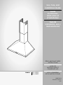
Use, Care, and
Installation Guide
Guide
d’utilisation,
d’entretien et
d’installation
Guía de
instalación, uso y
mantenimiento
READ AND SAVE THESE
INSTRUCTIONS
LISEZ CES
INSTRUCTIONS ET
CONSERVEZ-LES
LEA Y CONSERVE
ESTAS INSTRUCCIONES
LIB0178328
Printed in Mexico
11/21
Models: EVL430S3
EVL436S3

2
Contenido
ENGLISH �������������������������������������������������������������������������������������������������������������������������������������������������������2
Important Safety Notice ��������������������������������������������������������������������������������������������������������������������������������������������������������������������������������������������������������������� 3
Electrical & Installation Requirements ������������������������������������������������������������������������������������������������������������������������������������������������������������������������������������4
Product Dimensions �����������������������������������������������������������������������������������������������������������������������������������������������������������������������������������������������������������������������4
List of Materials ��������������������������������������������������������������������������������������������������������������������������������������������������������������������������������������������������������������������������������5
Parts no supplied�����������������������������������������������������������������������������������������������������������������������������������������������������������������������������������������������������������������������5
Ducting Options ������������������������������������������������������������������������������������������������������������������������������������������������������������������������������������������������������������������������������6
Ducting version ��������������������������������������������������������������������������������������������������������������������������������������������������������������������������������������������������������������������������6
Ductless (Recirculating) ���������������������������������������������������������������������������������������������������������������������������������������������������������������������������������������������������������6
Installation �����������������������������������������������������������������������������������������������������������������������������������������������������������������������������������������������������������������������������������������6
Install Range Hood �������������������������������������������������������������������������������������������������������������������������������������������������������������������������������������������������������������������������7
Electrical Connection ��������������������������������������������������������������������������������������������������������������������������������������������������������������������������������������������������������������������8
Complete Installation ���������������������������������������������������������������������������������������������������������������������������������������������������������������������������������������������������������������������9
Description of the Hood ���������������������������������������������������������������������������������������������������������������������������������������������������������������������������������������������������������������9
Control ������������������������������������������������������������������������������������������������������������������������������������������������������������������������������������������������������������������������������������������� 9
CFM Reduction System ��������������������������������������������������������������������������������������������������������������������������������������������������������������������������������������������������������������10
Mainteinance ����������������������������������������������������������������������������������������������������������������������������������������������������������������������������������������������������������������������������������� 10
Warranty �������������������������������������������������������������������������������������������������������������������������������������������������������������������������������������������������������������������������������������������� 11
ENGLISH
Contents
IAPPROVED FOR RESIDENTIAL APPLIANCES
FOR RESIDENTIAL USE ONLY
READ AND SAVE THESE INSTRUCTIONS
PLEASE READ ENTIRE INSTRUCTIONS BEFORE PROCEEDING.
INSTALLATION MUST COMPLY WITH ALL LOCAL CODES.
IMPORTANT: Save these Instructions for the Local Electrical Inspector’s use�
INSTALLER: Please leave these Instructions with this unit for the owner�
OWNER: Please retain these instructions for future reference�
Safety Warning: Turn o power circuit at service panel and lock out panel, before wiring this appliance�

3
Important Safety Notice
I CAUTION
FOR GENERAL VENTILATING USE ONLY� DO NOT USE TO
EXHAUST HAZARDOUS OR EXPLOSIVE MATERIALS OR
VAPOURS�
IWARNING
TO REDUCE THE RISK OF FIRE, ELECTRIC SHOCK, OR
INJURY TO PERSONS, OBSERVE THE FOLLOWING:
A� Use this unit only in the manner intended by the
manufacturer� If you have questions, contact the
manufacturer�
B� Before servicing or cleaning the unit, switch power o at
service panel and lock service panel disconnecting means
to prevent power from being switched on accidentally�
When the service cannot be locked, securely fasten a
prominent warning device, such as a tag, to the service
panel�
C� Installation work and electrical wiring must be done by
qualified person(s) in accordance with all applicable codes
& standards, including fire-rated construction�
D� Sucient air is needed for proper combustion and
exhausting of gases through the flue (Chimney) of fuel
burning equipment to prevent back- drafting�
Follow the heating equipment manufacturers guideline and
safety standards such as those published by the national
fire protection association (NFPA), the american society
for heating, refrigeration and air conditioning engineers
(ASHRAE), and the local code authorities�
E� When cutting or drilling into wall or ceiling, do not damage
electrical wiring and other hidden utilities�
F� Ducted fans must always be vented to the outdoor�
I CAUTION
To reduce risk of fire and to properly exhaust air, be sure to
duct air outside - do not vent exhaust air into spaces within
walls, ceilings, attics, crawl spaces, or garages�
IWARNING
TO REDUCE THE RISK OF FIRE, USE ONLY METAL DUCT
WORK�
Install this hood in accordance with all requirements specified�
IWARNING
To reduce the risk of fire or electric shock, do not use this
hood with any external solid state speed control device�
IWARNING
TO REDUCE THE RISK OF A RANGE TOP GREASE FIRE�
a) Never leave surface units unattended at high settings�
Boilovers cause smoking and greasy spillovers that may
ignite� Heat oils slowly on low or medium settings�
b) Always turn hood ON when cooking at high heat or when
flambeing food (I�e� Crepes Suzette, Cherries Jubilee,
Peppercorn Beef Flambe’)�
c) Clean ventilating fans frequently� Grease should not be
allowed to accumulate on fan or filter�
d) Use proper pan size� Always use cookware appropriate for
the size of the surface element�
e) Suitable for use in household cooking area�
IWARNING
TO REDUCE THE RISK OF INJURY TO PERSONS, IN THE
EVENT OF A RANGE TOP GREASE FIRE, OBSERVE THE
FOLLOWING:a
a) SMOTHER FLAMES with a close-fitting lid, cookie sheet, or
other metal tray, then turn o the gas burner or the electric
element� BE CAREFUL TO PREVENT BURNS� If the flames
do not go out immediately, EVACUATE AND CALL THE
FIRE DEPARTMENT�
b) NEVER PICK UP A FLAMING PAN - you may be burned�
c) DO NOT USE WATER, including wet dishcloths or towels -
a violent steam explosion will result�
d) Use an extinguisher ONLY if:
1) You know you have a class ABC extinguisher, and you
already know how to operate it�
2) The fire is small and contained in the area where it
started�
3) The fire department is being called�
4) You can fight the fire with your back to an exit�
aBased on “Kitchen Fire Safety Tips” published by NFPA�
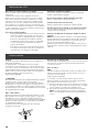
OPERATION
Always leave safety grills and filters in place� Without these
components, operating blowers could catch onto hair, fingers
and loose clothing�
The manufacturer declines all responsibility in the event of
failure to observe the instructions given here for installation,
maintenance and suitable use of the product�
The manufacturer further declines all responsibility for injury
due to negligence and the warranty of the unit automatically
expires due to improper maintenance�
ICAUTION
Automatically Operated Device - To Reduce The Risk Of
Injury Disconnect From Power Supply Before Servicing�

4
Electrical & Installation Requirements
IMPORTANT
Observe all governing codes and ordinances�
It is the customer’s responsibility:
• To contact a qualified electrical installer�
• To assure that the electrical installation is adequate and in
conformance with National Electrical Code, ANSI/NFPA
70 — latest edition*, or CSA Standards C22�1-94, Canadian
Electrical Code, Part 1 and C22�2 No�0-M91-latest edition**
and all local codes and ordinances�
• If codes permit and a separate ground wire is used, it is
recommended that a qualified electrician determine that
the ground path is adequate�
• Do not ground to a gas pipe�
• Check with a qualified electrician if you are not sure range
hood is properly grounded�
• Do not have a fuse in the neutral or ground circuit�
IMPORTANT
• Save Installation Instructions for electrical inspector’s use�
• The range hood must be connected with copper wire only�
• The range hood should be connected directly to the fused
disconnect (Or circuit breaker) box through metal electrical
conduit�
• Wire sizes must conform to the requirements of the
National Electrical Code ANSI/NFPA 70 — latest edition*,
or CSA Standards C22�1-94, Canadian Electrical Code Part
1 and C22�2 No� 0-M91 - latest edition** and all local codes
and ordinances�
• A U�L�- or C�S�A�-listed conduit connector must be provided
at each end of the power supply conduit (at the range
hood and at the junction box)�
Copies of the standards listed may be obtained from:
* National Fire Protection Association Batterymarch Park Quincy, Massachusetts
02269
** CSA International 8501 East Pleasant Valley Road Cleveland, Ohio 44131-5575
BEFORE INSTALLING THE HOOD
1 For the most ecient air flow exhaust, use a straight run
or as few elbows as possible�
CAUTION: Vent unit to outside of building, only�
2 At least two people are necessary for installation�
3 Fittings material is provided to secure the hood to most
types of walls/ceilings, consult a Qualified Installer, check
if they perfectly fit with your cabinet/wall�
4 Do not use flex ducting�
5 COLD WEATHER installations should have an additional
backdraft damper installed to minimize backward cold
air flow and a nonmetallic thermal break to minimize
conduction of outside temperatures as part of the
ductwork� The damper should be on the cold air side of
the thermal break�
The break should be as close as possible to where the
ducting enters the heated portion of the house�
Make up air: Local building codes may require the use of
Make-Up Air Systems when using Ducted Ventilation Systems
greater than specified CFM of air movement� The specified
CFM varies from locale to locale� Consult your HVAC profes-
sional for specific requirements in your area��
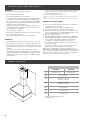
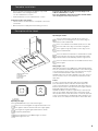
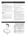
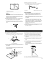
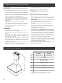
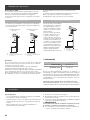
Product Dimensions
A
B
C
D
E
G
F
Models
EVL430S3 EVL436S3
A30” (76�2 cm) 36” (91�4 cm)
B1911⁄16” (50 cm)
C* Max: 421⁄8” (107 cm)
Min: 286⁄16” (72 cm)
D** Max: 383⁄16” (97 cm)
Min: 286⁄16” (72 cm)
E6” (15�24 cm)
F73⁄16” (18�3 cm)
G83⁄16” (20�8 cm)
* Ductless (Recirculating) version
** Ducted version

5
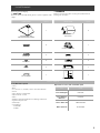
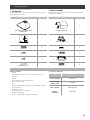
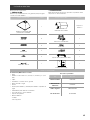
List of Materials
Removing the packaging�
I CAUTION
Remove carton carefully, Wear gloves to protect against sharp
edges�
I WARNING
Remove the protective film covering the product before
putting into operation�
Supplied Part Pieces Supplied Part Pieces
Hood assembly and
LED lamps already installed
1
Duct covers
2
5x45 mm 6
6” round air transition
1
5.4x75 mm 4
8x40 mm
2
3.5x9.5 mm 2
10x60 mm
4
4x8 mm 2
Duct cover bracket
1
Torx 10 adapter 1
Mounting template
1
Parts no supplied
Tools/Materials required
• Level
• Drill
• 11⁄4” (3�2 cm), 1⁄8” (3�2 mm), and 1⁄16” (4�8 mm) drill bits
• Pencil
• Wire stripper or utility knife
• Tape measure or ruler
• Pliers
• Caulking gun and weatherproof caulking compound
• Jigsaw or keyhole saw
• Metal snips
• Screwdrivers:
- Flat-blade
- Phillips
Optional accessories and consumable parts
KIT # Part
Recirculating Kit KIT02766
Long Chimney
Extension KIT02762
Grease Filters Kit GRI0009219B
Make up Air Kit KIT0148906

6
Ducting Options
CFM reduction kit
If required o desired this hood is to be used only in
conjunction with CFM reduction kit model KIT0175561�
Consult your HVAC professional and local building codes for
specific requirements in your area�
Ducting version
Closely follow the instructions set out in this manual�
All responsability, for any eventual inconveniences, damages
or fires caused by not complying with the instructions in this
manual, is declined�
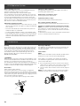
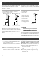
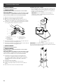
Ductless (Recirculating)
The hood is equipped with a 6” (15�2 cm) round transition
for discharge of fumes to the outside�
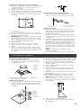
Roof Venting Wall Venting
A
B
A
B
A. Roof cap
B. 6” (15.2 cm) round vent
A. Wall cap
B. 6” (15.2 cm) round vent
In cases where it should not
be possible to discharge
cooking fumes and vapour
to the outside�
Attach a charcoal filter and
the deflector on the duct
cover support bracket�
Fumes and vapours are
recycled through the top
grille by means of a duct
connected to the transition
and the transition mounted
on the deflector�
For this version only:
purchase the Ductless
Recirculating Kit�
Minimum Duct Size:
6” Round Pipe�
B
A
A. Deector
B. 6” (15.2 cm) round vent
Preparation
Do not cut a joist or stud unless absolutely necessary� If a
joist or stud must be cut, then a supporting frame must be
constructed�
Fittings material is provided to secure the hood to most types
of walls/ceilings�
However, a qualified technician must verify suitability of the
materials in accordance with the type of wall/ceiling�
Before making cutouts, make sure there is proper clearance
within the ceiling or wall for exhaust vent�
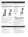
Recommended installation height:
Hood installation height above cooktop is the users preference�
The lower the hood is above the cooktop, the more ecient
the capturing of cooking odors, grease and smoke�
I CAUTION
Installation Heights
GAS cooktops 30″ (76�2 cm)
ELECTRIC cooktops 24″ (61 cm)
There is no maximum mounting height, however, we
recommend mounting the hood no greater than 36” (91�4
cm) above the cooking surface� For every inch (2�54 cm)
above 36” (91�4 cm), fume and moisture capture eciency
diminishes at an increasing rate and may not deliver an
acceptable level of ventilating performance�
This hood is intended for household use�
PLEASE READ THE INSTALLATION MANUAL FOR SPECIFIC
APPLICATION� Check your ceiling height and hood height
before selecting your hood�
Installation
Prepare location
• It is recommended that the vent system be installed before
hood is installed�
• Before making cutouts, make sure there is proper clearance
within the ceiling or wall for exhaust vent�
• Check your ceiling height and the hood height maximum
before you select your hood�
1 Disconnect power�
2 Determine which venting method to use: roof, wall, or
nonvented�
3 Select a flat surface for assembling the range hood�
Place covering over that surface�
I WARNING
TO REDUCE THE RISK OF FIRE, ELECTRIC SHOCK, OR
INJURY TO PERSONS, OBSERVE THE FOLLOWING�
4 Using 2 or more people, lift range hood onto covered
surface�
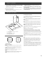
Mounting the duct cover bracket
1 Determine and mark the centerline on the wall where the
canopy hood will be installed� Disconnect power�
2 Select a mounting height from the Installation Heights
chart� Mark a reference line on the wall�
3 Tape template in place, aligning the template centerline
and bottom of template with hood bottom line and with
the centerline marked on the wall�

7
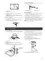
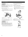
A
C
B
A. Centerline
B. Fastener locations
C. Mounting height reference (hood bottom line)
4 Mark centers of the fastener locations through the
template to the wall�
IMPORTANT: All screws must be installed into wood�
If there is no wood to screw into, additional wall framing
supports may be required�
5 Remove the template�
6 Drill 3⁄16” (4�8 mm) pilot holes at all locations where screws
are being installed into wood�
7 Install the 2 - 5 x 45 mm mounting screws� Leave a 1⁄4”
(6�4 mm) gap between the wall and the back of the screw
head to slide range hood into place�
1⁄4”
(6�4 mm)
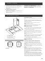
Vent cover bracket installation
1 Attach vent cover bracket to wall flush to the ceiling using
2 - 5 x 45 mm screws�
AC
D
B
A. 8 x 40 mm anchors
B. Centerline on wall
C. Vent cover support bracket
D. 5 x 45 mm screws
Complete preparation
1 Determine and make all necessary cuts in the wall for the
vent system� Install the vent system before installing the
hood� See “Venting Requirements” section�
2 Determine the required height for the home power supply
cable and drill a 1¼” (3�2 cm) hole at this location�
3 Run the home power supply cable according to the
National Electrical Code or CSA Standards and local codes
and ordinances� There must be enough ½” conduit and
wires from the fused disconnect (or circuit breaker) box to
make the connection in the hood’s electrical terminal box�
NOTE: Do not reconnect power until installation is complete�
4 Use caulk to seal all openings�
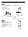
Install Range Hood
Connect Vent System
1 Install transition on top of hood (if removed for shipping)
with 2 - 3�5 x 9�5 mm screws using the Torx 10 adapter�
A
B
A. Vent transition
B. 3.5 x 9.5 mm screw
2 Remove protective film from hood and duct covers�
Install Range Hood
1 Using 2 or more people, hang range hood on 2 mounting
screws through the mounting slots on back of hood�
A
B
C
A. Mounting screws
B. Mounting slots
C. Lower mounting
screws
2 Mark with a pencil the lower mounting holes location�
3 Uninstall the hood assembly, and drill 3⁄16” (4�8 mm) pilot
holes at marked locations�
4 Hang the range hood again on 2 upper mounting screws�
5 Level the range hood and tighten upper mounting screws�
6 Install 2 - 5 x 45 mm lower mounting screws and tighten�
Use the optional wall anchors if needed�
7 Remove styrofoam protection from inside the hood�
For vented installations only:
1 Fit vent system over the exhaust outlet�
2 Measure from the bottom of the air deflector to the
bottom of the hood outlet� Cut the ductwork at the
measured dimension�
Dimension
to measure
Roof outlet
Wall
outlet
3 Seal connection with clamps�
4 Check that back draft dampers work properly�

8
Electrical Connection
I WARNING
ELECTRICAL SHOCK HAZARD�
I WARNING
DISCONNECT POWER BEFORE SERVICING�
REPLACE ALL PARTS AND PANELS BEFORE OPERATING�
FAILURE TO DO SO CAN RESULT IN DEATH OR
ELECTRICAL SHOCK�
1 Disconnect power�
2 Remove terminal box cover�
3 Remove the knockout in the terminal box cover and install
a UL listed or CSA approved 1⁄2” strain relief�
4 Run home power supply cable through strain relief, into
terminal box�
A
B
C
D
E
A. Home power supply cable
B. UL listed or CSA approved strain
relief
C. Black wires
D. UL listed wire connectors
E. White wires
F. Green (or bare) and yellow-green ground
wires
5 Use UL listed wire connectors and connect black wires (C)
together�
6 Use UL listed wire connectors and connect white wires (E)
together�
I WARNING
ELECTRICAL SHOCK HAZARD�
I WARNING
ELECTRICALLY GROUND BLOWER�
CONNECT GROUND WIRE TO GREEN AND YELLOW
GROUND WIRE IN TERMINAL BOX� FAILURE TO DO SO CAN
RESULT IN DEATH OR ELECTRICAL SHOCK�
7 Connect green (or bare) ground wire from home power
supply to yellow-green ground wire (F) in terminal box
using UL listed wire connectors�
8 Tighten strain relief screw�
9 Install terminal box cover�
10 Check that all light bulbs are secure in their sockets�
11 Reconnect power�
Install duct covers
• When using both upper and lower vent covers, push lower
cover down onto hood and lift upper cover to ceiling and
install with two mounting screws�
NOTE: For vented installations, the upper vent cover may
be reversed to hide slots�
C
A
B
C
D
A. Upper vent cover
B. Lower vent cover
C. 4 x 8 mm screws
D. Bracket
NOTE: To prevent scratches, lay paper or a kitchen towel over
the edges of the lower flue duct to protect the surface�

9
Complete Installation
• For non-vented (recirculating) installations only, install
charcoal filters over metal grease filter�
See the “Mainteinance” section�
• Install metal filters� See the “Mainteinance” section�
If range hood does not operate:
• Check that the circuit breaker is not tripped or the house
fuse blown�
• Disconnect power supply� Check that wiring is correct�
To get the most ecient use from your new range hood,
read the “Mainteinance” section.
Keep your Installation Instructions and Use and Care Guide
close to range hood for easy reference.
Description of the Hood
5
4
1
3
2
1. Blower and light controls
2. LED lamps
3. Grease lter handle
4. Grease lters
5. Duct covers
Control
A B
A. Light button
B. Blower button
Operating the light
The Light On/O button (A) controls both lights�
Press once for turning On soft light and the button sun
icon lightens with the bottom half of the edge slightly�
Press again for regular light and the button will be
completely illuminated�
Press a third time to turn O the light, the whole
button light turns o�
Operating the blower
Press the button (B) to turn On the hood on low
speed, the icon and right low corner of the edge on
button will be illuminated�
Press a second time for medium speed, the icon and
the lower half of the edge on the button enlightens�
Press again to high speed and ¾ of the edge on the
button will illuminate�
Press the button a fourth time to activate Boost speed
for five minutes (the full icon and edge will be illumi-
nated) and then, automatically switch to high speed�
Press the button a fifth time to turn Off the blower and
button lights�
Change light color
With lights and motor turned O, press and hold light button
for 3 sec, both buttons will fully illuminate on the current light
color� The buttons can be used to select desired color (Light
<< button backwards, Blower button forward >>)
Available light colors are white (default color), blue, green or
red� To set color, choose one and press both buttons at the
same time�
Sound
To enter sound mode, with lights and motor turned O
press both buttons at the same time and the upper left
corner of the light button will illuminate with white light� The
buttons can be used to select desired sound (Light <<button
backwards, Blower button forward>>)�
Available feedback sounds are regular beep, soft beep and
mute� As the regular and soft beep are selected, the hood
will reproduce each sound� When mute is selected, upper left
corner of the light button will illuminate with red light� To set
sound, choose one and press both buttons at the same time�

10
CFM Reduction System
Before operating your hood:
Some States and Provinces of the US & Canada restrict the
maximum exhausting airflow of range hoods�
Airflow is measured as cubic feet per minute (CFM)�
These maximum levels allowed are detailed in the local code
of your area� Please check local codes to find out if you need
to restrict the maximum airflow of your hood� If your local
code mandates a maximum airflow level below the maximum
airflow of this hood (i�e� 400 CFM), please execute the proce-
dure below to reduce the maximum airflow�
With blower and light turned O
• Press and hold both buttons at the same time for 3 sec you
will hear a beep and the icon lights (no edge) will illuminate
for 3 seconds�
• This action will disable speed 4 and eectively lower the
maximum airflow to > 300 CFM�
• Locate the CFM certification sticker in the hardware pack�
• Peel and Ax this sticker to a visible area in the blower�This
sticker provides ocial certification to your local inspector
that this hoods maximum airflow has been reduced to >
300 CFM�
Indicators of filter saturation:
At regular time intervals, the hood indicates the need of
performing filter maintenance�
Blower button icon blink (no edge):
Perform grease filter maintenance�
Light button blink (no edge):
Perform activated charcoal filter maintenance�
Reset of filter saturation indicators:
With blower Off press and hold the blower button for 3 sec�
Activation of saturation indicator activated charcoal filter:
NOTE: This operation must be performed with the hood off�
This indicator is normally deactivated; press and hold the
blower button for 3 sec� to activate the function: the button
blinks for 1 sec�
To deactivate the function, press and hold the blower button
for 3 sec�, the button blinks for half a sec�
Mainteinance
Cleaning
Do not spray cleaners directly to the control while cleaning the
Hood� The cooker hood should be cleaned regularly (at least
with the same frequency with which you carry out maintenance
of the fat filters) internally and externally� Clean using the
cloth dampened with neutral liquid detergent� Do not use
abrasive products� Do not use chlorine base cleaners�
DO NOT USE ALCOHOL!
I WARNING:
Failure to carry out the basic cleaning recommendations of the
cooker hood and replacement of the filters may cause fire risks�
Therefore, we recommend oserving these instructions�
The manufacturer declines all responsibility for any damage to
the motor or any fire damage linked to inappropriate maintenance
or failure to observe the above safety recommendations�
Grease Filter
Traps cooking grease particles�
This must be cleaned once a month using non aggressive
detergents, either by hand or in the dishwasher, which must be
set to a low temperature and a short cycle� When washed in
a dishwasher, the grease filter may discolour slightly, but this
does not affect its filtering capacity�
To remove the grease filter, pull the spring release handle�
A
A. Spring release handle
Replacing a LED Lamp
The LED lights are replaceable by a service technician only�
See “Who to contact” section in the warranty for service
contact information�
Charcoal filter
NOTE
When used in recirculation mode, To Reduce the Risk of Fire
and Shock use only conversion kit model KIT02766�
If the model is not vented to the outside, the air will be
recirculated through disposable charcoal filters that help
remove smoke and odors�
1 Cover the grill that protects the suction motor with the
carbon filter so that the slots on the filter correspond to
the pins on the sides of the motor protection grill�
2 Turn the carbon filter clockwise to block them (bayonet
fixing)�
NOTE: The charcoal filters cannot be cleaned� It should be
replaced every 4-6 months (depending on hood usage)�
ELICA North America
TWO-YEAR LIMITED WARRANTY
TO OBTAIN SERVICE UNDER WARRANTY
Owner must present proof of original purchase date. Please keep a copy of your dated proof of purchase (sales slip) in
order to obtain service under warranty.
PARTS AND SERVICE WARRANTY
For the period of two (2) years from the date of the original purchase, Elica will provide free of charge, non consumable
parts or components that failed due to manufacturing defects. During these two (2) years limited warranty, Elica will also
provide free of charge, all labor and in-home service to replace any defective parts.
WHAT IS NOT COVERED
• Damage or failure to the product caused by accident or act of God, such as, flood, fire or earthquake.
• Damage or failure caused by modification of the product or use of non-genuine parts.
• Damage or failure to the product caused during delivery, handling or installation.
• Damage or failure to the product caused by operator abuse.
• Damage or failure to the product caused by dwelling fuse replacement or resetting of circuit breakers.
• Damage or failure caused by use of product in a commercial application.
• Service trips to dwelling to provide use or installation guidance.
• Light bulbs, metal or carbon filters and any other consumable part.
• Normal wear of finish.
• Wear to finish due to operator abuse, improper maintenance, use of corrosive or abrasive cleaning products/pads and
• When the product has not been operated in accordance with the accompanying instructions for use.
oven cleaner products.
WHO IS COVERED
This warranty is extended to the original purchaser for products purchased for ordinary residential use in North America
(Including the United States, Guam, Puerto Rico, US Virgin Islands & Canada).
This warranty is non-transferable and applies only to the original purchaser and does not extend to subsequent owners of
the product. This warranty is made expressly in lieu of all other warranties, expressed or implied, including, but not limited
to any implied warranty of merchantability or fitness for a particular purpose and all other obligations on the part of Elica
North America, provided, however, that if the disclaimer of implied warranties is ineective under applicable law, the dura-
tion of any implied warranty arising by operation of law shall be limited to two (2) years from the date of original purchase
at retail or such longer period as may be required by applicable law.
This warranty does not cover any special, incidental and/or consequential damages, nor loss of profits, suered by the
original purchaser, its customers and/or the users of the Products.
WHO TO CONTACT
To obtain service under warranty or for any service related question:
USA & CANADA - Western Provinces
SERVICE POWER
888 732 8018
CANADA - Ontario Province
AGI Services
888 651 2534
CANADA - Quebec & Atlantic Provinces
Ateliers G. Paquette
800 463 0119
•
•
To ensure prompt after-sales service, when you call we will kindly ask you to provide the following information indicated
on the nameplate inside the hood: hood model, 12 NC and date of purchase on original invoice.To access the nameplate,
all you have to do is remove the grease filters.
•
Register your product in
elica.com
and earn a 3rd year of factory
warranty, covering all parts
plus in-home labor.
12NC:
Hood model:
Serial No:
Date of purchase on original invoice:

11
Warranty
ELICA North America
TWO-YEAR LIMITED WARRANTY
TO OBTAIN SERVICE UNDER WARRANTY
Owner must present proof of original purchase date. Please keep a copy of your dated proof of purchase (sales slip) in
order to obtain service under warranty.
PARTS AND SERVICE WARRANTY
For the period of two (2) years from the date of the original purchase, Elica will provide free of charge, non consumable
parts or components that failed due to manufacturing defects. During these two (2) years limited warranty, Elica will also
provide free of charge, all labor and in-home service to replace any defective parts.
WHAT IS NOT COVERED
• Damage or failure to the product caused by accident or act of God, such as, flood, fire or earthquake.
• Damage or failure caused by modification of the product or use of non-genuine parts.
• Damage or failure to the product caused during delivery, handling or installation.
• Damage or failure to the product caused by operator abuse.
• Damage or failure to the product caused by dwelling fuse replacement or resetting of circuit breakers.
• Damage or failure caused by use of product in a commercial application.
• Service trips to dwelling to provide use or installation guidance.
• Light bulbs, metal or carbon filters and any other consumable part.
• Normal wear of finish.
• Wear to finish due to operator abuse, improper maintenance, use of corrosive or abrasive cleaning products/pads and
• When the product has not been operated in accordance with the accompanying instructions for use.
oven cleaner products.
WHO IS COVERED
This warranty is extended to the original purchaser for products purchased for ordinary residential use in North America
(Including the United States, Guam, Puerto Rico, US Virgin Islands & Canada).
This warranty is non-transferable and applies only to the original purchaser and does not extend to subsequent owners of
the product. This warranty is made expressly in lieu of all other warranties, expressed or implied, including, but not limited
to any implied warranty of merchantability or fitness for a particular purpose and all other obligations on the part of Elica
North America, provided, however, that if the disclaimer of implied warranties is ineective under applicable law, the dura-
tion of any implied warranty arising by operation of law shall be limited to two (2) years from the date of original purchase
at retail or such longer period as may be required by applicable law.
This warranty does not cover any special, incidental and/or consequential damages, nor loss of profits, suered by the
original purchaser, its customers and/or the users of the Products.
WHO TO CONTACT
To obtain service under warranty or for any service related question:
USA & CANADA - Western Provinces
SERVICE POWER
888 732 8018
CANADA - Ontario Province
AGI Services
888 651 2534
CANADA - Quebec & Atlantic Provinces
Ateliers G. Paquette
800 463 0119
•
•
To ensure prompt after-sales service, when you call we will kindly ask you to provide the following information indicated
on the nameplate inside the hood: hood model, 12 NC and date of purchase on original invoice.To access the nameplate,
all you have to do is remove the grease filters.
•
Register your product in
elica.com
and earn a 3rd year of factory
warranty, covering all parts
plus in-home labor.
12NC:
Hood model:
Serial No:
Date of purchase on original invoice:

12
FRANÇAIS ������������������������������������������������������������������������������������������������������������������������������������������������� 12
Avis de Sécurité Important ������������������������������������������������������������������������������������������������������������������������������������������������������������������������������������������������������� 13
Exigences électriques et d’installation ���������������������������������������������������������������������������������������������������������������������������������������������������������������������������������14
Dimensions du Produit ����������������������������������������������������������������������������������������������������������������������������������������������������������������������������������������������������������������14
Liste des pièces ���������������������������������������������������������������������������������������������������������������������������������������������������������������������������������������������������������������������������� 15
Pièces non fournies ��������������������������������������������������������������������������������������������������������������������������������������������������������������������������������������������������������������� 15
Méthodes d’évacuation ��������������������������������������������������������������������������������������������������������������������������������������������������������������������������������������������������������������� 16
Version sans conduit (Recyclage) ������������������������������������������������������������������������������������������������������������������������������������������������������������������������������������ 16
Version à conduit �������������������������������������������������������������������������������������������������������������������������������������������������������������������������������������������������������������������� 16
Installation ��������������������������������������������������������������������������������������������������������������������������������������������������������������������������������������������������������������������������������������� 16
Installation de la hotte ���������������������������������������������������������������������������������������������������������������������������������������������������������������������������������������������������������������� 17
Connexion électrique ������������������������������������������������������������������������������������������������������������������������������������������������������������������������������������������������������������������� 18
Achever l’installation �������������������������������������������������������������������������������������������������������������������������������������������������������������������������������������������������������������������� 19
Description de la hotte ��������������������������������������������������������������������������������������������������������������������������������������������������������������������������������������������������������������� 19
Commandes ������������������������������������������������������������������������������������������������������������������������������������������������������������������������������������������������������������������������������ 19
Système de Réduction CFM �����������������������������������������������������������������������������������������������������������������������������������������������������������������������������������������������������20
Entretien ������������������������������������������������������������������������������������������������������������������������������������������������������������������������������������������������������������������������������������������20
Garantie �������������������������������������������������������������������������������������������������������������������������������������������������������������������������������������������������������������������������������������������� 21
FRANÇAIS
Table des matières
APPROUVÉ POUR LES APPAREILS DE TYPE RÉSIDENTIEL
POUR UNE UTILISATION RÉSIDENTIELLE SEULEMENT
LISEZ CES INSTRUCTIONS ET CONSERVEZ-LES
VEUILLEZ LIRE CES INSTRUCTIONS AU COMPLET AVANT DE COMMENCER.
L’INSTALLATION DE L’APPAREIL DOIT RESPECTER TOUS LES CODES EN VIGUEUR.
IMPORTANT : Conservez ces instructions afin de pouvoir les remettre à l’inspecteur-électricien de votre région�
INSTALLATEUR : Veuillez laisser ces instructions avec l’appareil pour le propriétaire�
PROPRIÉTAIRE : Veuillez conserver ces instructions pour pouvoir vous y référer plus tard�
Avertissement de sécurité : Coupez l’alimentation du circuit dans le panneau électrique et verrouillez le
panneau avant de raccorder les fils de cet appareil�
Exigence : 120 V c�a�, 60 Hz circuit de dérivation de 15 V c�a�, 20 Hz, de 15 ou 20 A�

13
Avis de Sécurité Important
I ATTENTION
UTILISER CET APPAREIL À DES FINS DE VENTILATION
GÉNÉRALE SEULEMENT� NE PAS UTILISER CET APPAREIL
POUR ÉVACUER DES MATÉRIAUX OU DES VAPEURS
DANGEREUX OU EXPLOSIFS�
I AVERTISSEMENT
POUR RÉDUIRE LES RISQUES D’INCENDIE, DE CHOC
ÉLECTRIQUE ET DE BLESSURE, RESPECTER LES DIRECTIVES
SUIVANTES:
A� Utiliser cet appareil uniquement aux fins prévues par le
fabricant� Si vous avez des questions à propos de l’appareil,
communiquez avec le fabricant�
B� Avant de faire l’entretien de l’appareil ou de le nettoyer,
coupez l’alimentation dans le panneau électrique et
verrouillez le panneau en bloquant le dispositif permettant
d’empêcher d’activer l’alimentation accidentellement� S’il
n’est pas possible de verrouiller l’accès au panneau, fixez
une étiquette très voyante au panneau électrique�
C� Une personne qualifiée doit eectuer l’installation et le
câblage des fils électriques en conformité avec tous les
codes et toutes les normes, y compris la cote de résistance
au feu�
D� Il est important de prévoir susamment d’air pour assurer
une bonne combustion de l’équipement de chaue et
l’évacuation adéquates des gaz par le conduit de cheminé
afin de prévenir les refoulements d’air� Respectez les
directives et les normes de sécurité des fabricants de
l’équipement de chauage, comme celles publiées par la
National Fire Protection Association (NFPA), la American
Society for Heating, Refrigeration and Air Conditioning
Engineers (ASHRAE) et le code des autorités de votre
région�
E� Au moment de couper ou de percer un mur ou un plafond,
assurez-vous de ne pas endommager la filerie électrique ou
tout autre accès à un service publique�
F� Il faut toujours évacuer à l’extérieur les systèmes conduit�
I ATTENTION
Pour réduire les risques d’incendie et évacuer l’air correctement,
assurez-vous que le conduit mène à l’extérieur; il ne faut pas
évacuer l’air dans l’espace entre les murs, dans les plafonds, dans
les greniers, les vides sanitaires ou les garages�
I AVERTISSEMENT
POUR RÉDUIRE DES RISQUES D’INCENDIE, UTILISEZ UNI-
QUEMENT DES CONDUITS EN MÉTAL�
Installez cette hotte en respectant toutes les exigences
mentionnées�
I AVERTISSEMENT
Pour réduire les risques d’incendie et de choc électrique,
n’utilisez pas cette hotte avec un contrôleur de vitesse à
semi-conducteurs�
I ATTENTION
Dispositif à commande automatique - pour réduire le risque
de Blessure Débrancher de l’alimentation électrique avant la
maintenance�
I AVERTISSEMENT
POUR RÉDUIRE LES RISQUES D’INCENDIE DE GRAISSE SUR
LES CUISINIÈRES�
a) Ne laissez jamais la cuisinière sans surveillance lorsqu’elle
est réglée à une haute température� Les débordements par
bouillonnement causent de la fumée et des débordements
de gras qui peuvent s’enflammer� Faites chauer l’huile
lentement, à une température basse ou moyenne�
b) Faites toujours fonctionner la hotte lorsque vous utilisez
la cuisinière à une haute température ou que vous faites
flamber des aliments (P� ex�: crêpes Suzette, cerises
jubilées, boeuf au poivre flambé)�
c) Nettoyez les hélices de ventilation fréquemment� Il ne faut
pas que la graisse s’accumule sur les filres ou les hélices�
d) Utilisez le bon format de casserole� Utilisez toujours un
chaudron de taille approprié à l’élément de la cuisinière�
e) Convient pour utilisation dans la zone de cuisson domestique�
I AVERTISSEMENT
POUR ÉVITER DE BLESSER QUELQU’UN LORS D’UN IN-
CENDIE DE GRAISSE SUR LA CUISINIÈRE, SUIVRE LES CON-
SEILS SUIVANTS:a
a) ÉTOUFFER LES FLAMMES avec un couvercle aux
dimensions de la taque de cuisson, une tôle à biscuit
ou tout autre plateau métallique, puis couper le gaz ou
l’alimentation électrique de la cuisinière� FAIRE ATTENTION
A NE PAS SE BRÛLER� Si les flammes ne s’éteignent pas
immédiatement, QUITTER LA PIÈCE ET APPELER LES
POMPIERS�
b) NE JAMAIS PRENDRE EN MAIN UNE CASSEROLE N FEU,
vous pourriez vous blesser�
c) NE PAS UTILISER D’EAU, y compris les essuies de vaisselle
ou les serviettes humides – une violente explosion due à la
vapeur formée pourrait survenir�
d) Utiliser un extincteur SEULEMENT si:
1) Vous êtes sûr d’avoir un extincteur de classe ABC que
vous savez utiliser�
2) Le feu est petit et confiné à la zone où il s’est formé�
3) Les pompiers ont été appelés�
4) Vous pouvez lutter contre le feu avec une sortie de-
rrière vous�
a Recommandations tirées des conseils de sécurité en cas d’incendie de cuisine
publiés par la NFPA��
MODE OPÉRATOIRE
Toujours laisser les grilles de sécurité et les filtres à leurv
place� Sans la présence de ces derniers, les parties aspirantes
pourraient attirer les cheveux, les doigts ou les vêtements�
Le fabricant décline toute responsabilité si les informations
détaillées dans ce manuel pour l’installation, l’entretien et
l’utilisation adéquate du produit ne sont pas observées� Le
fabriquant décline en outre toute responsabilité pour
d’éventuelles blessures dues à des négligences; en outre, la
garantie de l’appareil sera annulée suite à des conditions
d’entretien inappropriées� Cet appareil est fabriqué pour un
usage interne� Ne pas utiliser cet appareil à l’extérieur�

14
Exigences électriques et d’installation
IMPORTANT
Respectez tous les codes et les ordonnances en vigueur�
Le client a la responsabilité de :
• Contacter un électricien-installateur�
• Vérifier que l’installation électrique est adéquate et
conforme avec le Code national de l’électricité, ANSI/
NFPA 70 (la plus récente édition*), ou les normes C22�1-94,
Code canadien de l’électricité, Partie 1 et C22�2 No�0-M91
(La plus récente édition**) de la CSA, ainsi que tous les
codes et les ordonnances de votre région�
• Si le code le permet et que vous utilisez un fil de mise à la
tere distinct, il est recommandé de faire vérifier le chemin
du fil par un électricien�
• Ne pas mettre l’appareil à la terre sur une conduite de gaz�
• Consultez un électricien qualifié si vous n’êtes pas certain
que la hotte est mise à la terre correctement�
• N’installez pas un fusible dans le circuit neutre ou le circuit
de mise à la terre�
IMPORTANT
• Conservez ces instructions afin de pouvoir les remettre à
l’inspecteur-électricien�
• La hotte doit être câblée uniquement à l’aide de fils de
cuivre�
• Il faut raccorder la hotte directement à une boîte à fusible
ou à un disjoncteur par l’entremise d’une canalisation
électrique en métal�
• Le calibre de fil doit être conforme aux exigences du
Code national de l’électricité, ANSI/NFPA 70 (La plus
récente édition*), ou les normes C22�1-94, Code canadien
de l’électricité, Partie 1 et C22�2 0-M91 (La plus récente
édition**) de la CSA, ainsi que tous les codes et les
ordonnances de votre région�
• Il faut prévoir un connecteur de canalisation approuvé
par l’UL ou la CSA à chaque extrémité de la canalisation
d’alimentation (À la hotte et à la boîte de jonction)�
Vous pouvez obtenir un exemplaire des normes indiquées en vous adressant à:
* La National Fire Protection Association, Batterymarch Park Quincy, Massachuse-
tts, 02269
** La CSA International, 8501 East Pleasant Valley Road, Cleveland, Ohio, 44131-
5575
AVANT D’INSTALLER LA HOTTE
1 Pour assurer la ventilation la plus ecace possible,
installez la conduite en ligne droite ou avec le moins de
coudes possibles�
ATTENTION : La sortie de la conduite de ventilation doit
donner sur l’extérieur�
2 Deux personnes sont nécessaires pour eectuer
l’installation�
3 La quincaillerie fournie permet de fixer la hotte à la
plupart des murs et des plafonds; consultez un installateur
qualifié pour vous assurer que la quincaillerie fournie est
adaptée à votre type de mur ou d’armoire�
4 N’utilisez pas de conduit flexible�
5 Dans le cas des endroits sujets aux TEMPÉRATURES
FROIDES, il faut installer un clapet de contre-tirage
supplémentaire afin de minimiser le retour d’air froid et
un isolant thermique non métallique afin de minimiser la
conduction de la température extérieur dans le conduit�
Il faut placer le clapet du côté de l’air froid de l’isolant
thermique�L’isolant doit être placé le plus près possible de
l’endroit où le conduit entre dans la partie chauée de la
maison�
6 Air d’appoint : Le code du bâtiment de votre région
peut exiger l’utilisation d’un système d’air d’appoint si
vous utilisez un système de ventilation à conduit dont le
mouvement d’air dépasse un certain nombre de CFM�
Le nombre de pi3/min varie d’une région à l’autre�
Consultez un professionnel de CVC pour connaître les
exigences précises de votre région�
Dimensions du Produit
A
B
C
D
E
G
F
Models
EVL430S3 EVL436S3
A30” (76�2 cm) 36” (91�4 cm)
B1911⁄16” (50 cm)
C* Max: 421⁄8” (107 cm)
Min: 286⁄16” (72 cm)
D** Max: 383⁄16” (97 cm)
Min: 286⁄16” (72 cm)
E6” (15�24 cm)
F73⁄16” (18�3 cm)
G83⁄16” (20�8 cm)
* Seulement avec la version sans conduit (à recyclage)
** Seulement avec la version version à conduit

15
Liste des pièces
Retirer les pièces de leur emballage�
I ATTENTION
Enlever délicatement le carton, porter des gants pour se pro-
téger des bords coupants�
I AVERTISSEMENT
Enlever le film de protection recouvrant le produit avant de
commencer l’opération�
Pièces Fournies Quantité Pièces Fournies Quantité
Assemblage hotte avec souferie
et lampes DEL
1
Conduits de cheminée
2
Gabarit de montage
1
Transition ronde de 6”
1
5,4x75 mm 4
8x40 mm
2
3,5x9,5 mm 2
10x60 mm
4
4x8 mm 2Bride de support du
cache-conduit
1
Adaptateur Torx 10 15x45 mm 6
Pièces non fournies
Outils nécessaires
• Niveau
• Perceuse avec forets de 1¼” (3,2 cm), 1⁄8” (3,2 mm), y 1⁄16”
(4,8 mm)
• Crayon
• Pince à dénuder ou couteau utilitaire
• Mètre-ruban ou règle
• Pince
• Pistolet à calfeutrage et composé de calfeutrage résistant
aux intempéries
• Brides de conduit
• Scie sauteuse ou scie à guichet
• Cisaille de ferblantier
• Tournevis à lame plate et Phillips (Pozidrive)
Accessoires optionnel
KIT # Pièce
Kit de recyclage KIT02766
Caché Conduit
Extension Kit KIT02762
Filtre à graisse GRI0009219B
Kit d’air
conditionné KIT0148906

16
Méthodes d’évacuation
Kit de réduction CFM
Si nécessaire ou souhaité, cette hotte doit être utilisée unique-
ment avec le kit de réduction CFM modèle KIT0175561�
Consultez votre professionnel des installations de chauage
et les codes du bâtiment locaux pour connaître les exigences
spécifiques de votre région�
Version sans conduit (Recyclage)
Suivez à la lettre les directives présentées dans ce manuel�
Le fabricant refuse toute responsabilité en ce qui a trait à tout
préjudice, dommage ou incendie causé par la non observation
des directives contenues dans le présent manuel�
Version à conduit
La hotte est dotée d’une transition 6” (15,2 cm) afin
d’évacuer les vapeurs à l’extérieur�
Décharge à travers le toit Décharge à travers le mur
A
B
A
B
A� Bouche de décharge sur toit
B� Conduit rond de 6” (15,2 cm)
A� Bouche de décharge sur le mur
B� Conduit rond de 6” (15,2 cm)
S’il s’avère impossible
d’évacuer la fumée et
les vapeurs de cuisson à
l’extérieur, il est possible
de transformer la hotte
en version sans conduit
(Recyclage)� Fixer un filtre
au charbon et le déflceteur
sur le support de couvercle
de conduit� La fumée et la
vapeur sont recyclées�
Dans le cas de la version
sans conduit (à recyclage)
seulement: procurez-vous
la trousse de conversion en
hotte à recyclage�
B
A
A� Deflécteur
B� Conduit rond de 6” (15,2 cm)
Préparation
Ne coupez pas une solive ou un montant à moins qu’il soit
absolument nécessaire de le faire� Si vous devez couper une
solive ou un montant, vous devez construire un cadre de soutien�
La quincaillerie fournie permet de fixer la hotte à la plupart des
murs et des plafonds�
Vous devez cependant demander à un technicien qualifié de
vérifier la solidité des matériaux selon le type de mur ou de
plafond�
Avant de couper, assurez-vous qu’il y a un dégagement susant
dans le plafond ou le mur pour passer la conduite de sortie�
I ATTENTION
Hauteurs d’installation
Cuisinieres à gaz 30″ (76,2 cm)
Cuisinieres électriques 24″ (61 cm)
Il est recommandé d’installer cette hotte plus de 36” (91,4 cm)
au-dessus de la surface de cuisson� Par pouce (2,54 cm) supérieure
à 36” (91,4 cm) diminuera l’ecacité de la capture de la fumée et
de l’humidité, et la performance de ventilation�
S’IL VOUS PLAÎT LIRE L’INSTALLATION POUR UNE
INSTALLATION SPÉCIFIQUE� Avant de choisir la hotte, vérifiez la
hauteur du plafond et la hauteur maximale de la hotte�
Installation
Préparation de l’emplacement
• Il est recommandé d’installer le circuit d’évacuation avant de
procéder à l’installation de la hotte�
• Avant d’exécuter les découpages, vérifier la disponibilité
d’un dégagement susant dans le plafond ou le mur pour le
conduit d’évacuation�
• Avant d’installer la hotte, mesurer la hauteur libre sous
plafond et la hauteur maximum disponible sous la hotte�
1 Déconnecter la source de courant électrique�
2 Déterminer la méthode d’évacuation à utiliser: décharge à
travers le mur ou le toit, ou recyclage�
3 Sélectionner une surface plane pour l’assemblage de la
hotte� Placer le matériau de protection sur cette surface�
AVERTISSEMENT
POUR RÉDUIRE LE RISQUE D’INCENDIE, CHOC ÉLECTRIQUE
OU DOMMAGES CORPORELS, RESPECTER LES INSTRUCTIONS
SUIVANTES:
4 À l’aide de deux personnes ou plus, soulever la hotte et la
poser sur la surface couverte�
Installation des vis de montage de la hotte
1 Déterminer et marquer la position de l’axe central sur le
mur où la hotte sera installée�
2 Sélectionnez une hauteur de montage dans le tableau
Hauteurs d’Installation� Marquer la ligne de repérage sur
le mur�
3 Fixer le gabarit en place avec du ruban adhésif; aligner
l’axe central du gabarit et le bas du gabarit avec la ligne
correspondant au bas de la hotte, et avec l’axe central
déjà tracé sur le mur�

17
A
C
B
A� Axe central
B� Emplacements des attaches
C� Ligne de référence pour la hauteur de montage (bas de la hotte)
4 À l’aide du gabarit, marquer sur le mur le centre des
attaches�
IMPORTANT: Toutes les vis de montage de la hotte en îlot
doivent être vissées dans du bois où cela est possible� Si
l’on ne peut pas visser les vis de montage de la hotte dans
du bois, des tasseaux supplémentaires pour accrochage
mural seront peut-être nécessaires�
5 Retirer le gabarit�
6 Pour bois, percer des avant-trous de 3⁄16” (4,8 mm) à tous
les emplacements de pose des vis dans du bois�
7 Pour bois, installer les 2 vis de montage de 5 x 45 mm�
Laisser un espace de 1⁄4” (6,4 mm) entre le mur et l’arrière
de la tête de vis pour faire glisser la hotte et la mettre en
place�
1⁄4”
(6,4 mm)
Installation de la bride de cache-conduit
1 Fixer la bride du cache-conduit au mur en aeurement
avec le plafond à l’aide de 2 vis de 5 x 45 mm�
AC
D
B
A� 8 x 40 mm
B� Axe central
C� Bride de support du cache-conduit
D� Vis de 5 x 45 mm
Achever la Préparation
1 Déterminer et eectuer tous les découpages nécessaires
dans le mur pour le passage du circuit d’évacuation�
Installer le circuit d’évacuation avant la hotte� Voir la
section “Exigences concernant l’évacuation”�
2 Déterminer la hauteur appropriée pour le cordon
d’alimentation du domicile et percer un trou de 11⁄4” (3,2 cm)
à cet endroit�
3 Acheminer le câble d’alimentation du domicile selon
les prescriptions du Code national de l’électricité, des
normes CSA et des codes et règlements locaux� Il faut
que la longueur du conduit de 1⁄2” et des conducteurs soit
susante depuis le tableau de distribution (avec fusibles
ou disjoncteurs) pour réaliser le raccordement dans le
boîtier de connexion de la hotte�
REMARQUE: Ne pas mettre le système sous tension avant
d’avoir complètement terminé l’installation�
4 Utiliser un calfeutrant pour assurer l’étanchéité au niveau
de chaque ouverture�
Installation de la hotte
Raccordement du circuit d’évacuation
1 Installer le raccord de transition au sommet de la hotte (s’il
a été enlevé pour expédition), avec 2 vis de 3,5 x 9,5 mm�
A
B
A� Raccord de transition
B� Vis 3,5 x 9,5 mm
2 Retirer le film de protection des couvertures de la hotte et
des conduits
Installation de la hotte
1 À deux personnes au moins, suspendre la hotte aux 2
crochets de montage, à travers les encoches de montage
à l’arrière de la hotte� A
B
C
A� Vis de montage
B� Encoches de
montage
C� Vis de montage
inférieures
2 Mark avec un crayon les emplacements des trous inférieurs�
3 Désinstaller l’ensemble de la hotte et percer des trous
pilotes de 3⁄16 “(4,8 mm) aux emplacements marqués�
4 Remplacer le capot sur 2 haut les vis de montage�
5 Mettre la hotte de niveau et serrer les vis de montage
supérieures�
6 Installer les 2 vis de montage de 5 x 45 mm et serrer�
Utiliser les pièces d’ancrage mural facultatives si nécessaire�
7 Retirez la protection en polystyrène de l’intérieur de la
hotte
Pour les installations avec décharge à l’extérieur uniquement:
1 Le circuit d’évacuation doit être installé par dessus la
sortie d’évacuation�
2 Mesurer la distance entre le bas du déflecteur et le bas
de la sortie de la hotte� Couper le conduit à la dimension
mesurée�
Dimension
Déflecteur d’air
Prise
murale
3 Serrer le raccord avec des brides de serrage�
4 Vérifier que les clapets anti-retour fonctionnent correctement�

18
Connexion électrique
I AVERTISSEMENT
RISQUE DE CHOC ÉLECTRIQUE
I AVERTISSEMENT
DÉCONNECTER LA SOURCE DE COURANT ÉLECTRIQUE
AVANT L’ENTRETIEN�
REPLACER PIÈCES ET PANNEAUX AVANT DE FAIRE LA REM-
ISE EN MARCHE� LE NON-RESPECT DE CES INSTRUCTIONS
PEUT CAUSER UN DÉCÈS OU UN CHOC ÉLECTRIQUE�
1 Déconnecter la source de courant électrique�
2 Retirer le couvercle du boîtier de connexion�
3 Ôter l’opercule arrachable du boîtier de connexion et
installer un serre-câble de ½” (homologation UL ou CSA)�
4 Acheminer le cordon d’alimentation du domicile à travers
le serre-câble, dans le boîtier de connexion�
C
D
B
E
A
A� Câble d’alimentation électrique
du domicile
B� Conducteurs noirs
C� Connecteurs de fils
(homologation UL)
D� Conducteurs blancs
E� Conducteurs verts (ou
nus) ou vert-jaune de
liaison à la terre
5 Connecter ensemble les conducteurs noirs (B) à l’aide de
connecteurs de fils (homologation UL)�
6 Connecter ensemble les conducteurs blancs (D) à l’aide de
connecteurs de fils (homologation UL)�
I AVERTISSEMENT
RISQUE DE CHOC ÉLECTRIQUE
I AVERTISSEMENT
DÉCONNECTER LA SOURCE DE COURANT ÉLECTRIQUE
AVANT L’ENTRETIEN�
REPLACER PIÈCES ET PANNEAUX AVANT DE FAIRE LA REM-
ISE EN MARCHE� LE NON-RESPECT DE CES INSTRUCTIONS
PEUT CAUSER UN DÉCÈS OU UN CHOC ÉLECTRIQUE�
7 À l’aide des connecteurs de fils (homologation UL),
connecter le conducteur de liaison à la terre (vert ou
nu) du câble d’alimentation du domicile au conducteur
vertjaune de liaison à la terre (E) dans le boîtier de
connexion�
8 Serrer la vis du serre-câble�
9 Installer le couvercle du boîtier de connexion�
10 Vérifier que chaque ampoule est bien insérée dans sa
douille�
11 Reconnecter la source de courant électrique�
Installation des Cache-conduits
• En cas d’utilisation des sections supérieure et inférieure du
cache-conduit, pousser la section inférieure vers le bas, sur
la hotte et soulever la section supérieure vers le plafond et
installer avec 2 vis de montage�
REMARQUE: Pour les installations avec décharge à
l’extérieur, le cache-conduit supérieur peut être inversé
pour dissimuler les fentes�
C
A
B
C
D
A� Supérieure du cache-conduit
B� Inférieure du cache-conduit
C� Vis de 4,2 x 8 mm
D� Support
REMARQUE: Pour éviter les rayures, déposer du papier ou
une serviette de cuisine sur les bords du conduit de cheminée
inférieur pour protéger la surface�

19
Achever l’installation
• Pour les installations sans décharge à l’extérieur (recyclage)
uniquement, installer les filtres à charbon sur le filtre à graisse
métallique� Voir la section “Entretien”�
• Installer les filtres métalliques� Voir la section “Entretien”�
Si la hotte ne fonctionne pas :
• Vérifiez que le disjoncteur n’est pas déclenché ou que le
fusible de la maison n’est pas grillé�
• Débranchez l’alimentation électrique� Vérifiez que le
câblage est correct�
Pour tirer le meilleur parti de votre nouvelle hotte, lisez la
section “Entretien”.
Conservez les instructions d’installation et le guide d’utilisa-
tion et d’entretien à proximité de la hotte pour pouvoir les
consulter facilement.
Description de la hotte
5
4
1
3
2
1 Commandes du ventilateur et lampes
2 Lampes DEL
3 Poignée du filtre à graisse
4 Filtre à graisse
5 Conduits de cheminée
Commandes
A B
A. Bouton de l’éclairage
B. Bouton du ventilateur
Utilisation de la lumière
Le bouton Light On/O (A) permet de contrôler les deux
lumières�
Appuyez une fois pour allumer la lumière douce et
l’icône du bouton soleil s’illumine avec la moitié in-
férieure du bord légèrement�
Appuyez à nouveau pour une lumière normale et le
bouton sera complètement éclairé�
Appuyez une troisième fois pour éteindre la lumière,
l’ensemble de la lumière du bouton s’éteint�
Fonctionnement de la hotte
Appuyez sur le bouton (B) pour allumer la hotte en
basse vitesse, l’icône et le coin inférieur droit du bord
sur le bouton s’allument�
Appuyez une deuxième fois pour la vitesse moyenne,
l’icône et la moitié inférieure du bord sur le bouton
s’allument�
Appuyez une nouvelle fois sur le bouton pour la vites-
se élevée et les ¾ du bord sur le bouton s’allument�
Appuyez une quatrième fois sur le bouton pour activer
la vitesse Boost pendant cinq minutes (l’icône et le
bord complet s’illuminent), puis, passez automatique-
ment à la vitesse élevée�
Appuyez sur le bouton une cinquième fois pour étein-
dre la soufflerie et les lumières du bouton�
Changer la couleur de la lumière
Avec les lumières et le moteur éteints, appuyez et mainte-
nez le bouton de lumière pendant 3 sec, les deux boutons
s’allument complètement sur la couleur de lumière actuelle�
Les boutons peuvent être utilisés pour sélectionner la couleur
désirée (bouton Lumière << vers l’arrière, bouton Ventilateur
vers l’avant >>)�
Les couleurs de lumière disponibles sont le blanc (couleur par
défaut), le bleu, le vert ou le rouge� Pour définir la couleur,
choisissez-en une et appuyez sur les deux boutons en même
temps�
Son
Pour entrer en mode son, avec les lumières et le moteur
éteints, appuyez sur les deux boutons en même temps et le
coin supérieur gauche du bouton lumière s’illuminera d’une
lumière blanche� Les boutons peuvent être utilisés pour
sélectionner le son désiré (Lumière <<bouton vers l’arrière,
souffleur vers l’avant>>)�
Les sons de retour disponibles sont le bip régulier, le bip doux
et la sourdine� Lorsque le bip régulier et le bip doux sont sé-
lectionnés, la hotte reproduit chaque son� Lorsque la sourdine
est sélectionnée, le coin supérieur gauche du bouton lumi-
neux s’allume en rouge� Pour régler le son, choisissez-en un et
appuyez sur les deux boutons en même temps�

20
Système de Réduction CFM
Avant d’utiliser votre hotte:
Certains États et certaines provinces des États-Unis et du
Canada limitent le
le débit d’air maximum des hottes de cuisine�
Le débit d’air est mesuré en pieds cubes par minute (CFM)�
Ces niveaux maximums autorisés sont détaillés dans le code
local de votre région� Veuillez vérifier les codes locaux pour
savoir si vous devez restreindre le débit d’air maximal de votre
hotte� Si votre code local impose un niveau de débit d’air
maximum inférieur au débit d’air maximum de cette hotte
(c’est-à-dire 400 CFM), veuillez exécuter la procédure ci-des-
sous pour réduire le débit d’air maximum�
Avec le ventilateur et la lumière éteints
• Appuyez sur les deux boutons en même temps et mainte-
nez-les enfoncés pendant 3 secondes ; vous entendrez
un bip et les lumières de l’icône (sans bord) s’allumeront
pendant 3 secondes�
• Cette action désactivera la vitesse 4 et réduira eective-
ment le débit d’air maximum à > 300 CFM�
• Trouvez l’autocollant de certification CFM dans l’emballa-
ge du matériel�
• Cet autocollant fournit une certification ocielle à votre
inspecteur local que le débit d’air maximum de cette
hotte a été réduit à > 300 CFM�
Indicateurs de la saturation du filtre:
A intervalles réguliers, la hotte indique la nécessité de
d’effectuer l’entretien du filtre�
L’icône du bouton de la ventilation clignote (pas de bord):
Effectuez l’entretien du filtre à graisse�
Le bouton lumineux clignote (pas de bord):
Effectuez l’entretien du filtre à charbon actif�
Remise à zéro des indicateurs de saturation des filtres:
Lorsque le ventilateur est éteint, appuyez sur le bouton du
ventilateur et maintenez-le enfoncé pendant 3 secondes�
Activation de l’indicateur de saturation du filtre à charbon
actif:
NOTE: Cette opération doit être effectuée avec la hotte étein-
te�
Cet indicateur est normalement désactivé ; pour activer la
fonction, appuyez sur le bouton de soufflage pendant 3 se-
condes : le bouton clignote pendant 1 seconde�
Pour désactiver la fonction, appuyez sur le bouton de sou-
fflage pendant 3 secondes, le bouton clignote pendant une
demi-seconde�
Entretien
Nettoyage
Ne pas vaporiser de nettoyants directement sur le panneau
de contrôle lors du nettoyage de la Hotte La hotte doit être
régulièrement nettoyée à l’intérieur et à l’extérieur (au moins
à la même fréquence que pour l’entretien des filtres à graisse)�
Pour le nettoyage, utiliser un chion humidifié avec un
détergent liquide neutre� Ne pas utiliser de produit contenant
des abrasifs�
Ne pas utiliser de nettoyants à base de chlore�
NE PAS UTILISER D’ALCOOL!
I ATTENTION
Il y a risque d’incendie si vous ne respectez pas les
instructions concernant le nettoyage de l’appareil et le
remplacement ou le nettoyage du filtre�
La responsabilité du constructeur ne peut en aucun cas être
engagée dans le cas d’un endommagement du moteur ou
d’incendie liés à un entretien négligé ou au non respect des
consignes de sécurité précédemment mentionnées�
Filtre à graisse
Il retient les particules de graisse issues de la cuisson� Le
filtre doit être nettoyé une fois par mois avec des détergents
non agressifs, à la main ou dans le lave-vaisselle à faibles
températures et cycle rapide�
Le lavage du filtre anti-graisse métallique au lave-
vaisselle peut en provoquer la décoloration� Toutefois, les
caractéristiques de filtrage ne seront en aucun cas modifiées�
Pour démonter le filtre anti-graisse, tirer la poignée de
décrochement à ressort�
A
A� Poignée à ressort
Remplacement de la lampe à DEL
Les lumières DEL sont remplaçables par un technicien de
service seulement� Voir les informations de contact de service:
“Qui contacter”�
Filtres à charbon
REMARQUE
En mode de recirculation, pour réduire le risque d’incendie et
de choc, utilisez seulement des kits de conversion:
Kit de Recyclage: KIT02766
Si le système n’a pas d’évacuation vers l’extérieur, l’air va
circuler à travers des filtres à charbon jetables qui vont aider à
éliminer fumée et odeurs�
1 Posez le filtre à charbon comme couverture de la grille
qui protège le moteur aspirant de manière que les fentes
présentes sur le filtre correspondent aux pivots sur les
côtés de la grille protège-moteur�
2 Tournez le filtre à charbon dans le sens des aiguilles d’une
montre pour le bloquer (fixation à baïonnette)�
REMARQUE: Les filtres à charbon ne peuvent pas être
nettoyés� Il doit être remplacé tous les 4-6 mois (selon
l’utilisation de la hotte)�
La page est en cours de chargement...
La page est en cours de chargement...
La page est en cours de chargement...
La page est en cours de chargement...
La page est en cours de chargement...
La page est en cours de chargement...
La page est en cours de chargement...
La page est en cours de chargement...
La page est en cours de chargement...
La page est en cours de chargement...
La page est en cours de chargement...
La page est en cours de chargement...
-
 1
1
-
 2
2
-
 3
3
-
 4
4
-
 5
5
-
 6
6
-
 7
7
-
 8
8
-
 9
9
-
 10
10
-
 11
11
-
 12
12
-
 13
13
-
 14
14
-
 15
15
-
 16
16
-
 17
17
-
 18
18
-
 19
19
-
 20
20
-
 21
21
-
 22
22
-
 23
23
-
 24
24
-
 25
25
-
 26
26
-
 27
27
-
 28
28
-
 29
29
-
 30
30
-
 31
31
-
 32
32


ELICA EVL436S3 Guide d'installation
- Catégorie
- Hottes
- Taper
- Guide d'installation
dans d''autres langues
- English: ELICA EVL436S3 Installation guide
- español: ELICA EVL436S3 Guía de instalación

