
Signify Classified - Internal
www.lightolier.compage7/13/2021 1
442295520871
Installation Instruction
Calculite 2”
⚠WARNING & IMPORTANT
•This luminaire must be installed in accordance with National Electrical Code and local electrical and
construction regulations.
•To assure full compliance with local codes and regulations, check with your local electrical inspector before
installation.
To prevent electrical shock, turn off electricity at fuse box before installation.
•Product with no frame or installed with non-IC 2RN/2SN frames is not rated for insulation contact and
insulation must be kept 3 inches away from fixture sides and driver sides.
•Product is IC rated when installed with the 2RA/2SA frames only.
•Do not install if luminaire, parts or connectors are damaged.
•Product must be installed with provided or specified drivers and housing only. Use of other manufacturers'
components will void.
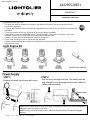
Light Engine Kit
Power Supply
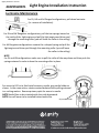
STEP 1
Remove knockout from frame with cover
STEP 2
Pass the wires through the hole. The cables must be
long enough for the dimming and the main cables (6
inches recommended).
NOTE: For the frame with no cover go to step 3 If you want to access the cable management,
please do it from the frame's rear door.
NOTE: For fully compliance apply silicon around to the perimeter of the bottom flanged
aperture.
REV .4 6/24/2021

Signify Classified - Internal
page7/13/2021 2
Light Engine Installation Instruction
442295520871
www.brandwebaddress.com
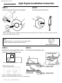
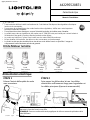
STEP 3
Remove knockout from driver assembly Pass the wires thru the hole
STEP 4
⚠WARNING
Before continuing with the installation make sure the driver assembly cover is in place, it is necessary to have a physical
ground and avoid any electric shock
STEP 6
Run wires to remote driver assyUse the hole cutout guide that comes
in the box to make ceiling cutout
STEP 5
Hole Cutout Guide Image Reference
Make ceiling cutout
NOTE:
For metal conduit, a 2‐1 connector can be used to allow
for daisy‐chaining multiple luminaires in series.
Flex‐Conduit Connector
Round: min 3.0” (76mm), max 3.2” (81mm)
Square: min 3.0”x3.0” (76x76mm), max 3.2”x3.2” (81x81mm)

Signify Classified - Internal
page7/13/2021 3
Light Engine Installation Instruction
www.brandwebaddress.com
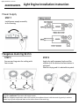
Power Supply
Flangeless mud-ring & trim
STEP 1
Secure mud ring onto the ceiling with
four screws
STEP 2
Apply dry wall compound and sand the
surface until the desired surface texture is
achieved.
Wait for drying and it is advisable to patch.
STEP 7
Install power supply assembly
to the housing
442295520871
NOTE: For flangeless application it is recommended to use #4 flat head wood screw with minimum length of 12mm
or 15/32in. Important: Contractor will supply screws.
NOTE: for flangeless application make sure to place the cardboard insert inside the mud ring cavity in order to
protect any dry wall compound leaks to the interior faces of the mud ring.
Cardboad insert

Signify Classified - Internal
page7/13/2021 4
Light Engine Installation Instruction
442295520871
7/13/2021
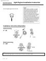
Push the light engine thru the hole
Rotational aiming
0° - 360°
Installation Instruction (Adjustable)
Vertical aiming
0° - 40°
NOTE:
For the adjustable light engines –An allen wrench (1.5mm) it’s provided by Signify

Signify Classified - Internal
page7/13/2021 5
Light Engine Installation Instruction
www.signify.com
7/13/2021
442295520871
Luminaire Maintenance
For DL, LW and AA flanged configurations, pull down luminaire
(i.e. reverse of installation).
For DL and LW flangeless configurations, pull the two springs inward on
the inside of the light engine and pull the light engine and driver pod
through the mounting collar (you will leave the collar in the ceiling)
For AA flangeless configurations remove the c-shaped spring and pull the
light engine and driver pod through the mounting collar (you will leave
the collar in the ceiling)
NOTE
For DL and LW configurations make sure to pull the collar all the way down and then push the
springs outward in order to have the mounting collar in place.
For access to LED or to field install accessory media, grip media holder as
shown. In the same action, rotate counterclockwise while pulling outward
in a rocking motion. Remove primary optic for access to media.
NOTE Media films to be oriented with shiny side downward.
NOTE Hex cell louver to be installed below media film. Grip media holder

Signify Classified - Internal
www.lightolier.compage7/13/2021 6
442295520871
Manuel d’installation
Calculite de 2po
⚠ATTENTION
•Cette luminaire doit être installé conformément le Code National Electrique et des régulations électriques
locales et de construction.
•Pour assurer la conformité avec des codes locales et des régulations, vérifier avec votre inspecteur
électrique local avant d’installer.
• Pour prévenir des chocs électriques, coupez l’électricité au boîter de fusibles avant d’installer.
•Le produit sans cadre ou installé avec des cadres non-IC 2RN/2SN n'est pas évalué pour contact isolant et
l'isolation doir être gardé à 3po des côtes du luminaire et des drivers.
•Le produit est évalué en IC quand il est installé avec les cadres 2RA/2SA seulement.
•Ne pas installer si la luminaire, des pièces ou des connecteurs sont endommagé.
• Le produit ne doit pas être installé qu’avec des drivers et de boîtier fournis ou spécifiés. L’usage de
composants d’autres fabricants annulera la garantie.
Kit de Moteur lumière
Alimentation électrique
ÉTAPE 1
Enlever l’entrée défonçable du cadre
avec couverture.
ÉTAPE 2
Faire passer les câbles dans le trou. Les câbles
doivent être suffisamment longs pour la gradation et
les câbles principaux (6po sont recommandés)
Bordure
rond Rond
Sans bordure Bordure
carré Carré
sans bordure Driver
NOTE: For the frame with no cover go to step 3 If you want to access the cable management,
please do it from the frame's rear door.
REMARQUE: Pour une conformité totale, appliquez du silicone autour du périmètre de la
bride inférieure.

Signify Classified - Internal
page7/13/2021 7
Manuel d’installation de Moteur lumière
www.brandwebaddress.com
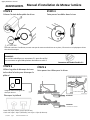
ÉTAPE 3
Enlever l’entrée defonçable du driver. Faire passer les câbles dans le trou
ÉTAPE 4
⚠ATTENTION
Avant de continuer l’installation, assurez-vous que la couverture du driver est en place, il faut avoir un sol physique et éviter
des chocs électriques.
ÉTAPE 6
Faire passer les câbles pour le driver
Utiliser la guide de découpe de trous
inclus dans la boite pour découper le
plafond
ÉTAPE 5
Image de référence de guide de
découpe de trous
Découper le plafond Connecter
Connecter
Noir
Vert
(sol)
Violet
Grise
(Si nécessaire)
Blanc
Boîtier IC
Kit Cadre Non-IC
REMARQUE:
Pour conduit métallique, un connecteur 2-1 peut être utilisé
pour connecter en guirnalde plusieurs luminaires en série 2. Connecteur de conduit flexible 2-1
442295520871
Rond: min 3.0po (76mm), max 3.2po (81mm)
Carré: min 3.0po x 3.0po (76x76mm), max 3.2po x 3.2po (81x81mm)

Signify Classified - Internal
page7/13/2021 8
Manuel d’installation de Moteur lumière
www.brandwebaddress.com
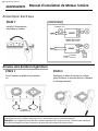
Alimentation électrique
Anneau sans bordure et garniture
ÉTAPE 1
Fixer l’anneau au plafond avec quatre
vis
ÉTAPE 2
Appliquer le plâtre et poncer la surface
jusqu’a obtenir la texture désirée. Attendre
le séchage complet.
ÉTAPE 7
Installer l’alimentation
électrique au boîtier.
Rouge
DEL
Bleu
Bleu
Violet
Grise
DEL
Rouge
Gradateur ELV
Gradateur
Schéma de câblage
442295520871
REMARQUE: Pour application sans bordure, il est recommandé d'utiliser le vis à bois à tête plate #4 avec longueur
minimale de 12mm ou 15/32po. Important: Les vis seront fournis par un consultant externe.
REMARQUE: Pour l'application sans bordure, assurez-vous de placer l'insert en carton à l'intérieur de la boîte en
métal afin de protéger leurs faces intérieures de toute fuite de composé de cloison sèche.
Cardboad insert

Signify Classified - Internal
page7/13/2021 9
Manuel d’installation de Moteur lumière
442295520871
7/13/2021
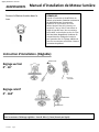
Pousser le Moteur lumière dans le
trou.
Réglage rotatif
0° - 360°
Instruction d’installation. (Réglable)
Réglage vertical
0° - 40°
Fixer l’angle
Fixer la position
Rotation de 360°
Inclination de 40°
REMARQUE:
Quand un luminaire est installé dans un
endroit qui a besoin d’entretien en dessous
du plafond à travers l’ouverture du
luminaire, les connections du circuit
doivent pouvoir être tirés à travers cet
ouverture. Pour ce faire, il faut utiliser un
câble de type NM avec des connecteurs
enfichables, un boucle de service de 12po
doit être laissé disponible à l’extérieur du
compartiment de câblage du luminaire
pour permettre tirer le câblage additionnel
avec les connecteurs enfichables à travers
l’ouverture du plafond.
REMARQUE:
Pour les moteurs d'éclairage réglables - Une clé Allen (1,5 mm) fournie par Signify

Signify Classified - Internal
page7/13/2021 10
Manuel d’installation de Moteur lumière
www.signify.com
442295520871
7/13/2021
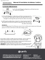
Luminaire Maintenance
For DL, LW and AA flanged configurations, pull down luminaire
(i.e. reverse of installation).
For DL and LW flangeless configurations, pull the two springs inward on
the inside of the light engine and pull the light engine and driver pod
through the mounting collar (you will leave the collar in the ceiling)
For AA flangeless configurations remove the c-shaped spring and pull the
light engine and driver pod through the mounting collar (you will leave
the collar in the ceiling)
REMARQUE
Pour les configurations DL et LW assurez-vous de tirer le collier tout le chemin vers le bas, puis
pousser les ressorts afin d’avoir le collier de montage en place.
Pour accéder au DEL ou installer l'accessoire optique, saisir le support de
média comme indiqué. Dans la même action, tourner dans le sens
antihoraire en tirant vers l'extérieur avec un mouvement de balancement.
Retirez l'optique principale pour accéder au média.
REMARQUE Les films doivent être orientés avec le côté brillant vers le bas
REMARQUE La grille de cellule hexagonale doit être installé sous le film.
saisir le support de média
-
 1
1
-
 2
2
-
 3
3
-
 4
4
-
 5
5
-
 6
6
-
 7
7
-
 8
8
-
 9
9
-
 10
10


Lightolier Calculite LED 2" Round Downlights, Wall Wash and Accents Install Instructions
- Taper
- Install Instructions
- Ce manuel convient également à
dans d''autres langues
Documents connexes
-
Lightolier Calculite LED 2" Round Downlights, Wall Wash and Accents Install Instructions
-
-
Lightolier Calculite LED 4" square gen 3 Install Instructions
-
Lightolier Calculite LED 3" Square Downlights, Wall Wash and Accents Install Instructions
-
-
-
-