
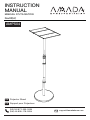
INSTRUCTION
MANUAL
MANUEL D'UTILISATION
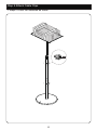
Projector Stand
Support pour Projecteur
EN
FR
Rev00(A)
AMPS04
(US/CA) 877-200-3259
(UK) 44-808-178-0934 [email protected]

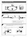
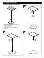
Min: 33.9″ (860mm)
Max: 45.1″ (1145mm)
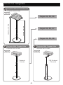
• Choisissez votre configuration
• Projecteur sans trou fileté
• Projecteur avec trou fileté • Projecteur avec trou fileté
A
Projector Without Threaded Hole
B
Projector With Threaded Hole
Choose Your Configuration
Page 06
C
Projector With Threaded Hole
Pages 04, 05, 06
Pages 04, 05, 07
Pages 04, 05, 08
NOT Included
Non inclus
NOT Included
Non inclus
NOT Included
Non inclus
· Centered
· Centrée
· Off Centered
· Décentré
Page 07 Page 08
02

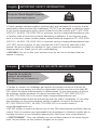
• Check package contents against supplied parts and hardware list to ensure that all
components were received and undamaged. DO NOT use damaged or defective parts.
lf you require replacement parts, please contact technical support at 877-200-3259
(US/CA) / 44-808-178-0934 (UK) or customer service at [email protected].
• Carefully read all instructions before attempting installation. If you have any ques-
tions or concerns, please contact please contact technical support at 877-200-3259
(US/CA) / 44-808-178-0934 (UK) or customer service at [email protected].
• DO NOT use this product for any purpose that is NOT explicitly specified in this
manual. We are not liable for damage or injury caused by incorrect assembly or
inappropriate use. Thank you for your understanding.
• WARNING: For use on flat, level surfaces only. Do not use on surfaces that are
uneven or sloping.
11 lbs
(5kg)
• Vérifiez le contenu de l'emballage par rapport aux pièces fournies et à la liste de
matériel pour vous assurer que tous les composants ont été reçus et en bon état. NE
PAS utiliser de pièces endommagées ou défectueuses. Si vous avez besoin de pièces
de rechange, veuillez contacter le support technique au 877-200-3259 (US/CA) /
44-808-178-0934 (UK) ou le service client à [email protected].
• Lisez attentivement toutes les instructions avant de tenter l'installation. Si vous avez
des questions ou des préoccupations, veuillez contacter le support technique au
877-200-3259 (US/CA) / 44-808-178-0934 (UK) ou le service client à
• NE PAS utiliser ce produit à des fins qui ne sont PAS explicitement spécifiées dans ce
manuel. Nous ne sommes pas responsables des dommages ou blessures causés par un
montage incorrect ou une utilisation inappropriée. Merci pour votre compréhension.
• AVERTISSEMENT: Pour une utilisation sur des surfaces planes et de niveau unique-
ment. Ne pas utiliser sur des surfaces inégales ou en pente.
Projector Stand Weight Capacity
Do not exceed weight capacity.
English IMPORTANT SAFETY INFORMATION
Français INFORMATIONS DE SÉCURITÉ IMPORTANTE
11 livres
(5kg)
Capacité de poids du
support de projecteur
Ne dépassez pas la capacité de
charge.
03

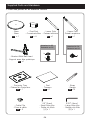
Supplied Parts and Hardware
· Base
· Base
· Foot Pad
· Coussinets Bas
5/32″ (4mm)
· Large Allen Key
· Grande clé Allen
[B] x 1
· Cable Clip
· Pince à câble
· Bracket With Ball Head
· Support avec tête sphérique
· Lower Pole
· Poteau inférieur
· Upper Pole
· Poteau supérieur
1/8″ (3mm)
· Small Allen Key
· Petite clé Allen
[A] x 1
• Liste des pièces et du matériel fournis
x 1
01 x 4
02 x 1
03 x 1
04
x 1
05
· Strap
· Sangle
x 2
08
x 2
09
· Projector Tray
· Plateau du Projecteur
x 1
06
· Pad
· Tampon
x 1
07
a
c
b
Attached to 03
Rattaché au 03 Attached to 04
Rattaché au 04
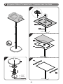
04

5/32″
(4mm)
Step 1 Attach Foot Pads to Base
• Étape 1 Fixer les patins à la base
01
02
Step 2 Connect Poles to Base and Attach Other Parts to Pole End
b
c
B
a
1
2
· Twist the lock to extend upper pole, then
twist to fasten.
· Tourner le verrou pour déployer le mât
supérieur, puis le tourner pour le fixer.
· Unscrew parts on two ends of pole assembly and save for later use.
· Dévissez les pièces aux deux extrémités du mât et conservez-les
pour une utilisation ultérieure.
03 04
• Étape 2 Connecter les poteaux à la base et attacher les autres pièces à
l'extrémité du poteau
05

NOT Included
Non inclus
B5/32″
(4mm)
06
07
1
2
3
4
08
08
06
04
a
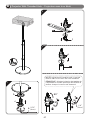
A
Projector Without Threaded Hole · Projecteur sans trou fileté
c
b
01
06

NOT Included
Non inclus
1/8″
(3mm)
d
e
f
90°
· NOTE: Adjust the tilt tension bolt if the ball
head is hard to tilt with the lock loosened.
· REMARQUE : Ajustez le boulon de tension de
l'inclinaison si la tête sphérique est difficile à
incliner lorsque le verrou est desserré.
A
2
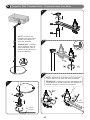
B
Projector With Threaded Hole · Projecteur avec trou fileté
2
3
d
04
B5/32″
(4mm)
1
c
b
01
05
07

· NOTE: Adjust the tilt tension bolt if the ball
head is hard to tilt with the lock loosened.
· REMARQUE : Ajustez le boulon de tension de
l'inclinaison si la tête sphérique est difficile à
incliner lorsque le verrou est desserré.
90°
1/8″
(3mm)
C
Projector With Threaded Hole · Projecteur avec trou fileté
· NOTE: Position the
bracket with ball head
toward the center of
base for stability.
· REMARQUE : Position-
nez le support avec la
tête sphérique vers le
centre de la base pour
plus de stabilité.
05
04
a
2
3
4
NOT Included
Non inclus
B5/32″
(4mm)
1
c
b
01
A
08

· NOTE: Remove the projector before
height adjustment.
· REMARQUE : Retirer le projecteur
avant de procéder au réglage de la
hauteur.
1
2
3
Step 3 Adjust the Height
• Étape 3 Réglage de la hauteur
NOT Included
Non inclus
09

Step 4 Attach Cable Clips
• Étape 4 Fixer les attaches de câble
09
NOT Included
Non inclus
10


-
 1
1
-
 2
2
-
 3
3
-
 4
4
-
 5
5
-
 6
6
-
 7
7
-
 8
8
-
 9
9
-
 10
10
-
 11
11
-
 12
12


dans d''autres langues
- English: Amada AMPS04 User manual
Autres documents
-
BenQ LU935ST Manuel utilisateur
-
BenQ LU951ST Guide d'installation
-
Epson BrightLink Pro 1410Wi Guide d'installation
-
Epson PowerLite 580 for SMART Guide d'installation
-
Epson BrightLink 595Wi Guide d'installation
-
Optoma OWM3000ST Manuel utilisateur
-
-
AVF PP703-A Guide d'installation
-
Peerless Industries PRG-UNV Manuel utilisateur