Castorama Cuisine toute équipée All in Basic Assembly Instructions
- Taper
- Assembly Instructions

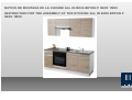
NOTICE DE MONTAGE DE LA CUISINE ALL IN BOIS BETON P INOX 1M90
INSTRUCTION FOR THE ASSEMBLY OF THE KITCHEN ALL IN BOIS BETON P
INOX 1M90

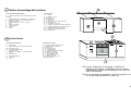
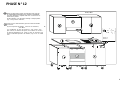
La cuisine est présentée dans sa configuration avec l' évier à
droite, il est possible d'inverser cet élément et de le monter à
gauche:
- porte meuble haut 60 (1)
- porte meuble bas 60 1 tiroir + 1 porte (2)
- plan de travail réversible (3)
- évier réversible (4)
Les portes sont réversibles; des pré-perçages pour les
poignées sont présentes en partie haute et basse sur les 2
côtés, ceci afin de permettre une ouverture à gauche ou à
droite.
F
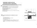
ASSEMBLY INTRODUCTION
INTRODUCTION AU MONTAGE
1
2
3
4
Pg. A
In this leaflet, the kitchen is presented in its right version with the
sink to the right side.
However, the elements are all reversible to allow assembly of the
kitchen either on the left or right side, and consequently all the
elements of the kitchen:
-Reversible wall unit front door (1)
-Reversible front of the base unit 1 drawer+1 front 60cm (2)
-Reversible worktop (3)
-Reversible sink (4)
All front doors are reversible, they all have pre-drilled holes to allow
left or right opening
KITCHEN CONFIGURATION L+R / CONFIGURATION DE LA CUISINE
EN

F
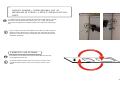
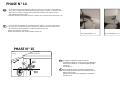
- Que ce soit pour la porte du meuble bas 60 (1 tiroir+1 porte) ou pour le
meuble haut 60, dévisser les vis des bases des charnières des portes
(photo 25), inverser le côté des charnières puis revisser les bases des
charnières (photo 26).
F
- Le plan de travail est fourni avec le chant sur le 2 cotés, mais il
peut être monté soit avec le trous pour l'évier à gauche, soit à
droite.
FOTO/PHOTO 25 FOTO/PHOTO 26
Pg. B
EN
- For both the base unit 60 (1 drawer+1 front) and the wall unit 60 unscrew
the base of the hinges from the cabinet (pic. 25) , rotate and position
the front to the right, then screw the hinges to the right of the cabinet (pic.
26)
2.
- BASE 60 1 DRAWER + 1 DOOR AND WALL UNIT 60
- MEUBLE BAS 40 1 TIROIR + 1 PORTE ET MEUBLE HAUT 40 1
PORTE
EN
-The worktop can be fitted on the kitchen either with the sink hole
on the right and on the left. .
3. WORKTOP / PLAN DE TRAVAIL

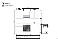
Meuble s
Oven base 60 cm
1 Tiroir - 1 Porte
Base 40
1 Drawer - 1 Door
Wall unit 40
72
EN
Hotte /Hood
80
Wall Unit 80
4
Fireresisitqantworktop 4 cm
Plinth
80 cm
Instructions
Notice
56
216
Meuble bas 40
Meuble bas
Sink base unti
190 cm
80 cm
Pg.1
200 cm
40 cm
40 cm

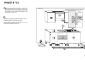
LISTE DES ELEMENTS PRÉ-ASSEMBLÉS :
B - Rails de suspension pour meubles hauts de 2m à
recouper
C - Meuble haut 60 cm. (intégré dans le meuble K)
D - Meuble haut 60 cm. avec hotte intregree
E - Meuble haut 80 cm.
I - Meuble bas 60 cm. 1 tiroir - 1 porte
J - Four
K - Meuble sous-évier
L - Plan de travail
M - Mitigeur
N - Evier
QUINCAILLERIE
N° 4
Pieds
N° 7 Poignée + 20 vis
N° 60 Cache-vis
N° 14 Vis de liaison
N° 3 Equerres
N° 6 Vis 4x18 mm pour Plan de travail
N° 18 Vis 3x35 mm
N° 1 Evacuation pour évier
N° 1 Crochets et bande de silicone pour évier
N° 2 Profilé de finition pour plan de travail
N° 2 Profilé de finition pour plinthe
N° 1 Elément de liaison pour plinthe
Notice de montage
F
Notice demontagedelacuisine
M
EN
Instructions
LISTAOGGETTI DELL’IMBALLO:
B.- Hanging Bar
C.- Wall unit 60 cm. (in the sink base unit K)
with reversibile door
D.- Wall unit 60 with hood
E - Wall unit 80 cm.
I - Base 60 cm.-1 drawer - 1 reversible door
J - Oven
K.- Sink base unit
L.- Reversible worktop
M. - Mixer tap
N.- Sink
Pg.2
HARDWARE INCLUDED:
N° 3 set of 4 supports for base units
N° 8 Handles with 16 screws
N° 60 hole caps
N° 14 coupling screws
N° 3 L shaped plates
N° 6 screws 4x18 mm for worktop
N° 18 screws 3,5x35 mm
N° 1 Siphon pipe for sink
N° 1 Set of hooks for sink
N° 2 Back splash end
N° 2 Work top finishing end
Instruction manual
N.B. Avant d'effectuer le montage, contrôler la
présence des pièces. Aménagez-vous un espace
suffisamment important et préparer tous tous les
outils nécessaires.
N.B. Prior starting the assembly check the presence of
all above listed elements in the box

Wall/ Mur
F
Particular 4 / Detail 4
Section Mur avec ø8 mm. perçage Wall Section with ø8 mm hole
Screws 6x50 Vis 6x50
Dowels Fischer type MKZ 8
Cheville MKZ 8
Pg.3
EN
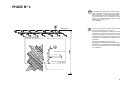
210
Tracer sur le mur une droite à une hauteur de
210 cm d'une longueur de 200cm.
Positionner le haut de la cornière de suspension
murale (B) le long de cette droite, puis marquer
tous les perçages sur le mur (tous les 30cm
maximum). Percer les trous à l'aide d'un foret de
diamètre 8 mm (adapter au diamètre de vos
chevilles).
Placer les chevilles dans ces trous :
ATTENTION UTILISER LES CHEVILLES
ADAPTER A LA NATURE DE VOTRE MUR.
Et visser la cornière avec les vis de 6x50mm
(Voir détail 4)
To position the hanging bar, please sign on the
wall from flooring a line at 210cm height , and
200 cm lenght . Lean the hanging bar on the
sign of the wall, (B) then make the holes every
30 cm of the bar . Use a drill bit ø mm. 8; use
Fischer type dowels MKZ8, then fix then bar
with screws mm. 6 x 50.
- See detail 4
PHASE N° 1

Adjust the hooks (g) of the wall units (they should hang
out of the furniture 1 cm) then hook the wall unit to the
hanging bar (B)in the following order (C-E) see page 2.
To regulate the position of the wall unit, operate the
regulator (r).
Attention! During the regulation of the height of the wall
unit , lift the furniture and operate the regulator (r)
EN
Attention! Pendant le réglage des meubles hauts,
soutenir légèrement le meuble afin de faciliter la mise à
niveau .
Pg.4
F
2 vis sont présentes sur les boîtiers de suspension des
meubles hauts :
-1 vis permettant le réglage de profondeur du meuble
-1 vis permettant le réglage de hauteur du meuble
Extraire les crochets (g) des suspensions murales des
meubles hauts, de 10mm. Accrocher
les meubles hauts à la cornière dans l'ordre C/D/E
(configuration page 2)
Pour régler la position des meubles hauts,
visser et dévisser les 2 vis présentent sur les boîtiers.
There are 2 screws on the inside of the wall unit (R)
-One screw adjusts the height of the wall unit
-One screw adjusts the depth of the wall unit
PHASE N° 2

Accrocher le meuble haut 60 (C ) à la
cornière (B). Aligner le haut du meuble (C)
Utiliser les réglages des boîtiers de suspension
(voir phase 4).
F
Bubble Level / Niveau Wall
210
216
Pg.5
Hook the wall unit 60 (C) to the hanging bar
(B). Level the top part of the wall unit (C)
regulating the hooks as explained in phase 4
EN
PHASE N° 3
Bubble level / Niveau

F
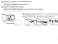
PHASE NO. 4 - MONTAGE DE LA HOTTE (D)
Attention : notice d'utilisation de la hotte dans le colis de la HOTTE
Parts to be aligned
Parties à aligner
Put on the floor the hood wall unit (D) with the top part upside down (Pic 1) Allign the filter with the front part
of the wall unit.(D). Lift the cover of the hood (p). See picture 1-2. Fix the filter with 4
screws mm.3,5x15. See picture 3.
EN
F
Pg.6
Picture/Dessin1 Picture /Dessin2
Picture /Dessin3
PHASE NO. 4B - ASSEMBLY OF THE HOOD WALL UNIT
Please refer to the instruction manual of the hood
/
PHASE NO. 4B - MONTAGE MEUBLE HAUT SUR HOTTE AVEC HOTTE INTEGREE
Attention : notice d'utilisation de la hotte dans le colis de la HOTTE
Mettre au sol le meuble hotte (D) sur la partie supérieure (retourné).Addosser et aligner la hotte avec l ecôté
antérieur du meuble de la hotte (D). Décrocher et lever le couvercle de la hotte en pressant sur
les pommeaux (p). Voir dessins 1 et 2. Fixer la hotte avec 4 vis 3.5x15mm. Voir dessin 3.
EN
PHASE NO. 4 – ASSEMBLY OF THE FREE STANDING HOOD
Please refer to the instruction manual of the hood

Wall / Mur
Pg.7
Accrocher le meuble haut 60 avec hotte integree(D) à la cornière
Accrocher le meuble haut 80 (E) à la cornière
(B). Aligner le haut du meuble 80
(E) avec la partie haute de la hotte (D) et la traverse haute du
meuble C .
Utiliser les réglages des boîtiers de suspension
(voir phase 4)
F
210
216
EN
Hook the wall unit 60(D) and he wall unit 90 (E)
to the hanging bar (B). Then level the wall unit 90
(E) and 60 (D) adjusting the hooks as shown in
phase 4.
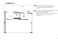
PHASE N° 5

Wall / Mur
Montage des étagères pour meubles
hauts
Emboîter un des côté dans les perçages prévus
à cet effet, puis baisser délicatement la tablette
jusqu'à l'emboîtement du côté opposé
(voir détail des taquets à ressort).
F
Detail/ Détail
Pg.8
EN
Assembly of the shelves
Position one side of the shelf , inserting the shelf support
into the hole as shown in the detail pictures (p)
Then push down the opposite side of the shelf to hook
the other shelf support to the furniture. See detail p .
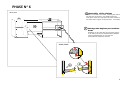
PHASE N° 6

Wall / Mur
Detail 2 / Détail 2
F
BottomView / Vue de la traverse basse
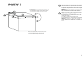
Coucher le meuble bas (I) sur le côté ou sur le dos.
Emboîter les pieds sous la traverse basse (voir détail 2).
Mettez le meuble de niveau. Utiliser les pieds pour le
réglage.
Pg.9
EN
Lean the base (I) on the side , then insert
the supports to the bottom of the furniture as
shown in detail 2 . Now stand up the base ,
and level the height (operating on the
supports as shown in phase 2)
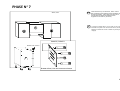
PHASE N° 7
Bubble level / Niveau

Wall / Mur
Bubble level / Niveau
Enlever le four du meuble bas four, sous le four se trouve une niche fermée par une
porte (fi). Coucher le meuble (J) sur le côté ou sur le dos, emboîter les pieds sur la
traverse basse.
Relever le meuble four sur ses pieds et le positionner.
Mettre de niveau le meuble. Aligner le dessus des meubles bas ainsi que les chants
arrières et avants.
Assembler ensuite les caissons à l'aide des vis de liaison (vt) dans les trous (6)
prévues à cet effet.
Attention, certaines vis sont déjà montées dans les meubles (J-A).
Attention, n'installez le four que lorsque l'ensemble de la cuisine est montée.
F
Pg.10
EN
Take out the oven from its compartment . Lean the base unit on the side
and insert the supports as done before ( see pag 9 detail 2)
Stand up the base unit, and pulli t together with the next base (I )
Level the base unit operating the supports as shown in phase 2 (page 4)
Insert the coupling screw (6), then scew tightly paying attention to the
screws already fitted in the furniture.
Once finished the fitting of the oven base unit, please re-insert the oven.
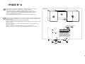
PHASE N° 8

Wall / Mur
Bubble level / Niveau
Coucher le meuble sous-évier (K) sur le côté ou sur le
dos, emboîter les pieds sous la traverse basse.
Relever le meuble sous-évier sur
ses pieds et le positionner sur le côté du meuble four (J),
mettre à niveau le meuble (en réglant les pieds voir,
phase 2), pour les parties hautes ainsi que les chants
avants et arrières
des caissons (J).
Assembler ensuite les caissons à l'aide des vis de liaison
(vt) dans les trous (7) prévues à cet effet.
Attention, certaines vis sont déjà montées dans le meuble
(J).
Monter les étagères comme pour les meubles hauts.
F
Pg.11
EN
Lean the sink base unit (K) and insert the support as done
previously ( see page 9 detail 2)
Stand up the base unit then pull it together with the oven
base unit (J), then level it with the oven base unit base
operating on the supports as done in phase 2 (page 4)
Now insert the coupling screw into the hole (7), the screw
tightly paying attention to the screw already fitted in the
furniture (J) Assemble the shelves as shown in phase 8
detail 6.
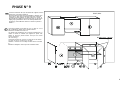
PHASE N° 9

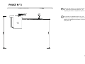
Place the worktop on sawhorse as shown (L) Place the fixing hooks (gl) on the
internal edge of the sink (N). See detail 14.
EN
F
Pg.12
Poser le plan de travail (L) déjà percé sur
deux tréteaux.
Appliquer les
bandes de silicone autour de l'évier (voir détail 13).
Monter les crochets (gl), qui se trouvent dans l’emballage de l'évier, sur
les perçages se trouvant sur les bords de l'évier (N).
Voir détail 14.
PHASE N° 10

Position the sink (L), into the biggest hole as shown in the picture, then rotate the hooks towards the
outside of the sink (N) . Tighten the hooks as shown in detail 15 .
NOTE: we strongly recommend to involve a plumber in the fitting of the mixer tap and the drain pipe
EN
F
Pg.13
Clsmp the screws Serrer tous les crochets
Bottom of the wporktop/ Envers du plan de travai
Detail/ Détail 15
M
Mettre l’évier sur le plan de travail (L), tourner les crochets vers l’extérieur de l’évier (N) . Il sera fixé, en
mettant en tension les crochets (gl). CONSEIL : s'adresser à un plombier pour monter le mitigeur (M) et
l'évacuation de l'évier
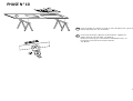
PHASE N° 11

Detail 21
Détail 21
Wall / Mur
Visser sur les côtés intérieurs gauche et droit du meuble
sous-évier
(K) les 2 équerres de fixation (avec les vis 4x18 mm.).
Voir détail
21. Positionner le plan de travail (L) avec l’évier et le
plan cuisson, au dessus des joues, en le collant au mur et à
la colonne réfrigérateur (A). Fixer le plan de travail (L) aux
joues à l'aide des équerres de fixation (sq) et les vis 4x18
mm.
de
F
Pg.14
EN
Apply on both internal edge left and right of the sink (K)
2 L shaped plates(sq) through screws 4x18 mm .Look detail 21
Lean the worktop (L) complete with sink on the bases as
shown in the picture
Fix the worktop (L) to the bases through L shaped plates
(sq) using screws 4x18 mm.,
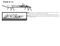
PHASE N° 12

Wall / Mur
Kickplatesectionwithhook/ Section du plinthe aveccrochet
Detail22/Détail 22
F
Introduire les clips dans la rainure de la plinthe (gm) et
les positionner face aux pieds des meubles.
Relever les plinthes et les fixer aux pieds
(pour les plinthes latérales (R), introduire les clips (gm)
retournés dans la rainure). Voir détail 22.
Positionner les profilés de finition (tz).
Hook
postion on
the kickplate
(P) and (R)
Position des
clips sur
plinthe (P)-
(R)
Pg.15
EN
Position the kick plate (P), (Q) and(R), in front of the
base .Slide the spring hooks(gm) into its housing . Lift
the long kick plate (P) mt. 1,9 and push to clip it to the
base supports . For the side kick plates (R) the hooks
(gm) must be insert up side down See detail 22. Then
insert terminal elements (tz).
PHASE N° 13

EN
- To fix the handle on the base 60 (1 drawer +1 pull out ) and that of the wall unit
60 1 front, complete the handle holes applying a piece of wood to exterior of the
front door as shown in picture 20 to protect the finishing, then pierce the pre-
pierced holes from the inside.
To fix the handles of the other furniture, tighten the screws from the inside (pic. 21)
- Pour monter les poignée sur le meuble bas 60 (1 tiroir + 1 porte) et le meuble
haut 60, percer à travers des pré-percages en utilisant une cale de bois sur la
face extérieure de la porte afin d'éviter les éclats (photo 20)
Monter les poignées (photo 21).
Monter les poignées des autres meubles (photo 21).
F
PICTURE/PHOTO 20
Pg.16
PICTURE/PHOTO 21
PHASE N° 14
To adjust the position of the front doors,
Top/bottom tighten or ease screws (z) positioning
the hinges as desired. To regulate depth operate
screw (w)
See picture 9.
WallUnit/ Meublehaut
Picture 9
Dessin9
EN
F
Pour régler les portes en hauteur, désserrer les
vis (z) et pousser les bases de charnières vers le
haut ou vers le bas.
Utiliser les vis (W) pour le réglage de profondeur
Voir dessin 9.
PHASE N° 15

Pg.21
Marinelli Cucine S.r.l.
Marinelli Cucine S.r.l.
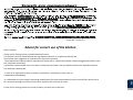
Advice for correct use of the kitchen
Dear Customer,
Thank you for having chosen a product Marinelli Cucine .
This kitchen has been manufactured with top quality materials, in compliance with EU law.
Here below some suggestion to maximize life- span of this product:
-The predominant material used to manufacture this kitchen is a particular wooden melamine agglomerate which has a
low tolerance to humidity.
Is therefore recommended not to use water to clean up the kitchen, but use specific products for washable surfaces.
The worktop is waterproof.
-In case of an high concentration of steam in the kitchen, ventilate the room a dry up
condensation immediately.
-It is advisable to use the hood in aspirating mode (look at the instruction attached to the charcoal filter) which has to
be connected through an whole on the wall to maximize the emission of steam.
Thank you for having chosen one of our products, we wish you all the best.
-
 1
1
-
 2
2
-
 3
3
-
 4
4
-
 5
5
-
 6
6
-
 7
7
-
 8
8
-
 9
9
-
 10
10
-
 11
11
-
 12
12
-
 13
13
-
 14
14
-
 15
15
-
 16
16
-
 17
17
-
 18
18
-
 19
19
-
 20
20


Castorama Cuisine toute équipée All in Basic Assembly Instructions
- Taper
- Assembly Instructions
dans d''autres langues
Autres documents
-
LAZER CADRE MODULAIRE OZ Le manuel du propriétaire
-
Proline FBI 1249 DWP Operating Instructions Manual
-
Bertazzoni PROF304CEMXE Guide d'installation
-
Bertazzoni MAST304INMXE Installation Manual for Induction Ranges
-
Bertazzoni PROF366QBXT Le manuel du propriétaire
-
Bertazzoni MAST365DFMXE Installation Manual Electric oven ranges