
Eective: 04-28-23
Replaces: 11-15-22
P/N: 100-10000111 Rev. 05
This manual should be maintained in legible condition and kept adjacent to the heater or in a safe place for future
reference.
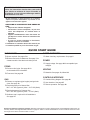
WARNING: If the information is not followed exactly, a re or explosion may result causing property
damage, personal injury or death.
— Do not store or use gasoline or other flammable vapors and liquids or other combustible materials
in the vicinity of this or any other appliance. To do so may result in an explosion or fire.
— WHAT TO DO IF YOU SMELL GAS
• Do not try to light any appliance.
• Do not touch any electrical switch; do not use any phone in your building.
• Immediately call your gas supplier from a neighbor’s phone. Follow the gas supplier’s instructions.
• If you cannot reach your gas supplier, call the fire department.
— Installation and service must be performed by a qualified installer, service agency or the gas supplier.
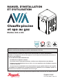
INSTALLATION AND
OPERATION MANUAL
Gas-Fired Pool
and Spa Heater
Models 264 and 404
SCAN WITH QR EQUIPPED SMART
DEVICE FOR ONLINE MANUAL.
SEE PAGE 94 FOR QR CODE.
NOTICE

2
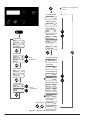
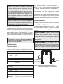
QUICK START GUIDE
CLEARANCES
Space required: See pages 7-9.
Minimum and service clearances: See page 7 for
clearances table. Note that local codes prevail.
PIPING
Pressure relief valve: See page 21 for
recommended PRV orientation.
Flow rates: See page 19.
GAS
Distance to regulator (pipe lengths) and gas inlet
sizes: See page 19.
Required pressure for Natural Gas:
Min = 3.5" WC (Dynamic), Max = 10.5" WC (Static)
Required pressure for Propane Gas:
Min = 8.0" WC (Dynamic), Max = 13" WC (Static)
Sediment trap is required for all installations:
See page 18.
WATER CHEMISTRY
Water chemistry requirements: See page 5.
POWER
Supply voltage: See page 24 for acceptable input
voltages.
VENTING
Materials: See pages 13, 15 and 16.
CONTROLS INTERFACE
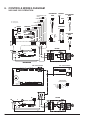
Controls Wiring diagram: See page 26.
User interface: See page 27.
Remote operation: See page 36.
Revision 5 reflects the following changes: Warranty removed from manual. Global warranty (100-10000378) replaces the old
warranty. Added "Gas Regulator Best Practices" to page 19. Added "or Z-Flex 2SVSNA04.5" to note in Table H. Removed "Level
0 through Level 2 Flow" call outs for item 7-H in IPL.
AAVERTISSEMENT: Assurez-vous de bien
suivre les instructions données dans cette notice
pour réduire au minimum le risque d’incendie ou
d’explosion ou pour éviter tout dommage matériel,
toute blessure ou la mort.
Ne pas entreposer ni utiliser d’essence ou ni d’autres
vapeurs ou liquides inammables à proximité de cet
appareil ou de tout autre appareil.
QUE FAIRE SI VOUS SENTEZ UNE ODEUR DE
GAZ:
• Ne pas tenter d’allumer d’appareil.
• Ne touchez á aucun interrupteur; ne pas vous
servir des téléphones se trouvant dans la
bâtiment.
• Appelez immédiatement votre fournisseur de
gaz depuis un voisin. Suivre les instructions du
fournisseur.
• Si vous ne pouvez rejoindere le fournisseur,
appelez le service es incendies.
L’installation et l’entretien doivent être assurés par
un installeur qualié ou par le fournisseur de gaz.

3
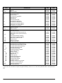
TABLE OF CONTENTS
1. WARNINGS ............................................................. 4
Pay Attention to These Terms ................................. 4
General Safety ........................................................5
2. WATER CHEMISTRY ............................................. 5
Automatic Chlorinators and Chemical Feeders.......5
3. BEFORE INSTALLATION ...................................... 6
Receiving equipment...............................................6
Rating and certications ..........................................6
Elevation ................................................................. 6
Required Power Supply .......................................... 6
Ambient Temperature Rating .................................. 6
4. INSTALLATION ....................................................... 6
Installation Codes ...................................................7
Clearances ..............................................................7
Outdoor Heater Installation .....................................7
Combustion and Ventilation Air .............................10
Direct Vent and Ducted Combustion Air Systems..10
Venting .................................................................. 13
Gas Supply Connections.......................................18
Flow Rates ............................................................19
ProTek Shield Assembly........................................ 20
Unitherm Governor Operation ...............................20
Internal Automatic Bypass Valve ...........................21
External Auxiliary Bypass Valve ............................ 21
Auxiliary Bypass Valve Adjustment ....................... 21
Pressure Relief Valve Installation .......................... 21
Plumbing Diagram.................................................23
Water/Flue Connection Reversal .......................... 24
5. ELECTRICAL WIRING ......................................... 24
Electrical Power Draw ...........................................24
Transformer Wiring ...............................................25
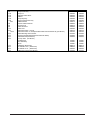
6. CONTROLS WIRING DIAGRAM ........................ 26
7. CONTROLS ........................................................... 27
Heater Top Removal ............................................. 27
Control Adjustments ............................................. 27
Operation .............................................................. 28
Service Menus ...................................................... 28
Program Menu ...................................................... 31
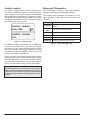
Control Lockout .....................................................34
Status and Diagnostics ......................................... 34
Remote Mode Selector - Installation
and Operation ..............................................36
Time Clock/Fireman’s Switch ................................38
8. OPERATING INSTRUCTIONS ............................ 44
Before Start-Up .....................................................44
Start-Up Procedures ............................................. 44
9. MAINTENANCE AND CARE ............................... 47
Cold Weather Operation ....................................... 47
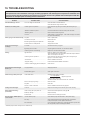
10. TROUBLESHOOTING ......................................... 48
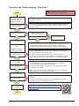
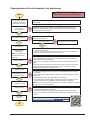
Operation and Troubleshooting - Flow Chart ........ 49
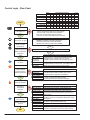
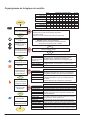
Control Logic - Flow Chart .................................... 50
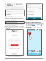
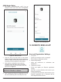
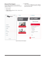
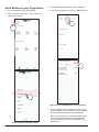
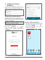
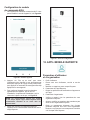
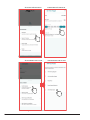
11. CONNECT TO WI-FI WITH RAYMOTE .............. 51
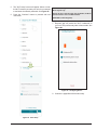
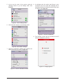
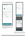
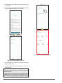
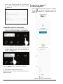
Preparing the Unit for Connection .........................52
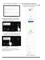
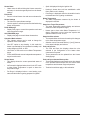
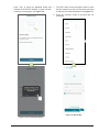
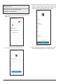
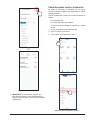
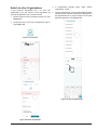
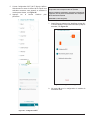
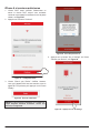
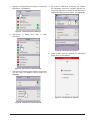
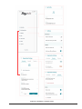
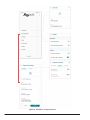
Add a New Heater to Raymote ............................. 52
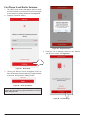
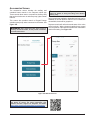
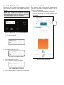
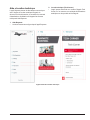
For iPhone 6 and Earlier Versions ........................ 56
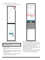
AVIA Heater Setup ................................................58
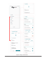
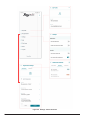
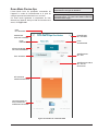
12. RAYMOTE MOBILE APP ..................................... 58
User and Organization Settings ............................58
Help and Tech Support ......................................... 61
Main View ..............................................................62
Automation ............................................................63
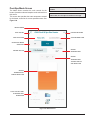
Pool-Spa Mode Screen .........................................65
Accessories Screen .............................................. 67
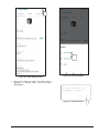
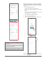
Reset Wi-Fi Credentials ........................................68
Reconnect to Wi-Fi................................................68
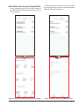
Add a New User to your Organization...................73
Client Accounts: Invite a Contractor ...................... 75
Partner Accounts: Invite New Clients .................... 77
Switch to other Organizations ...............................79
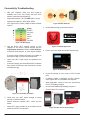
Connectivity Troubleshooting ................................ 80
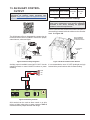
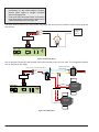
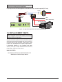
13. AUXILIARY CONTROL OUTPUT ...................... 81
14. REPLACEMENT PARTS ..................................... 83
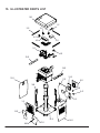
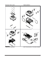
15. ILLUSTRATED PARTS LIST .............................. 84
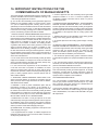
16. IMPORTANT INSTRUCTIONS FOR THE
COMMONWEALTH OF MASSACHUSETTS ... 93
17. QR CODES ............................................................ 94

4
AWARNING: Gasoline, as well as other ammable
materials and liquids (adhesives, solvents, etc.), and
the vapors they produce, are extremely dangerous. Do
not handle, use, or store gasoline or other ammable or
combustible materials in the vicinity of a heater.
AWARNING: Improper installation, adjustment,
alteration, service, or maintenance can cause property
damage, personal injury or loss of life. Installation
and service must be performed by a qualied installer,
service agency, or the gas supplier.
AWARNING: Do not install within 3 feet (0.9 m) of
a heat pump or an outdoor condensing unit. Strong
air intake from this type of equipment can disturb the
combustion process and cause damage or personal
injury.
AWARNING: UL-recognized fuel gas detectors are
recommended in all enclosed propane and natural
gas applications wherein there is a potential for an
explosive mixture of fuel gas to accumulate and their
installation should be in accordance with the detector
manufacturer’s recommendations and/or local laws,
rules, regulations, or customs.
AWARNING: The heater shall not be located in an
area where water sprinklers, or other devices, may cause
water to spray through the cabinet louvers and into the
heater. This could cause internal rusting or damage
electrical components, causing damage which will not
be covered under warranty.
1. WARNINGS
Pay Attention to These Terms
ADANGER Indicates the presence of immediate hazards which will cause severe personal injury, death or
substantial property damage if ignored.
AWARNING Indicates the presence of hazards or unsafe practices which could cause severe personal injury,
death or substantial property damage if ignored.
ACAUTION Indicates the presence of hazards or unsafe practices which could cause minor personal injury
or product or property damage if ignored.
CAUTION CAUTION used without the warning alert symbol indicates a potentially hazardous condition
which could cause minor personal injury or product or property damage if ignored.
NOTE Indicates special instructions on installation, operation, or maintenance which are important but
not related to personal injury hazards.
AWARNING: Both natural gas and propane have
an odorant added to aid in detecting a gas leak. Some
people may not physically be able to smell or recognize
this odorant. If you are unsure or unfamiliar with the
smell of natural gas or propane, ask your local gas
supplier. Other conditions, such as “odorant fade,”
which causes the odorant to diminish in intensity, can
also hide, camouage, or otherwise make detecting a
gas leak by smell more dicult.
AWARNING: To minimize the possibility of improper
operation, serious personal injury, re, or damage to the
heater:
• Always keep the area around the heater free of
combustible materials, gasoline, and other ammable
liquids and vapors.
• Heater should never be covered or have any blockage
to the ow of fresh air to the heater.
AWARNING: This unit contains refractory ceramic
ber (RCF) insulation in the combustion chamber. RCF,
as manufactured, does not contain respirable crystalline
silica. However, following sustained exposure to very
high temperatures [greater than 2192°F (1200°C), the
RCF can transform into crystalline silica (cristabolite).
The International Agency for Research on Cancer
(IARC) has classied the inhalation of crystalline silica
(cristabolite) as carcinogenic to humans.
When removing the burner or heat exchanger, take
precautions to avoid creating airborne dust and avoid
inhaling airborne bers. When cleaning spills, use wet
sweeping or High Eciency Particulate Air (HEPA)
ltered vacuum to minimize airborne dust. Use feasible
engineering controls such as local exhaust ventilation
or dust collecting systems to minimize airborne dust.
Wear appropriate personal protective equipment
including gloves, safety glasses with side shields, and
appropriate NIOSH-certied respiratory protection,
to avoid inhalation of airborne dust and airborne ber
particles.

5
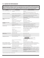
Recommended Level(s) Fiberglass Pools Fiberglass Spas Other Pool and Spa Types
Water Temperature 68-88°F (20-31°C) 89-104°F (31-40°C) 68-104°F (20-40°C)
pH 7.3-7.4 7.3-7.4 7.6-7.8
Total Alkalinity (ppm) 120-150 120-150 80-120
Calcium Hardness (ppm) 200-300 150-200 200-400
Salt (ppm) 4500 Maximum 4500 Maximum 4500 Maximum
Free Chlorine (ppm)* 2-3 2-3 2-3
Total Dissolved Solids (ppm) 3000 Maximum** 3000 Maximum** 3000 Maximum**
*Free Chlorine MUST NOT EXCEED 5 ppm!
**In saltwater chlorinated pools, the Total Dissolved Solids (TDS) can be as high as 6000 ppm.
Table A. Pool Water Chemistry
General Safety
Elevated water temperature can be hazardous. The
U.S. Consumer Product Safety Commission has these
guidelines:
1. Spa water temperatures should never exceed 104°F
(40°C). A temperature of 100°F (38°C) is considered
safe for a healthy adult. Special caution is suggested
for young children.
2. Drinking of alcoholic beverages before or during spa
or hot tub use can cause drowsiness which could
lead to unconsciousness and subsequently result in
drowning.
3. Pregnant Women Beware! Soaking in water over
102°F (39°C) can cause fetal damage during the first
three months of pregnancy resulting in the birth of a
brain-damaged or deformed child. Pregnant women
should stick to the 100°F (38°C) maximum rule.
4. Before entering the spa or hot tub, users should check
the water temperature with an accurate thermometer;
spa or hot tub thermostats may err in regulating water
temperatures by as much as 4°F (2.2°C).
5. Persons with a medical history of heart disease,
circulatory problems, diabetes, or blood pressure
problems should obtain a physician’s advice before
using spas or hot tubs.
6. Persons taking medications which induce
drowsiness, such as tranquilizers, antihistamines, or
anticoagulants, should not use spas or hot tubs.
2. WATER CHEMISTRY
NOTE: Corrosive water voids all warranties.
Chemical imbalance can cause severe damage to your
heater and associated equipment. Maintain your water
chemistry according to Table A. If the mineral content
and dissolved solids in the water become too high, scale
forms inside the heat exchanger tubes, reducing heater
eciency and damaging the heater. If the pH drops below
7.2, this will cause corrosion of the heat exchanger and
severely damage the heater. Heat exchanger damage
resulting from chemical imbalance is not covered by
the warranty.
For your health and the protection of your pool equipment,
it is essential that your water be chemically balanced. The
following levels must be used as a guide for balanced
water.
ACAUTION: Free chlorine must not exceed 5 ppm
which can damage the heater and is not covered under
warranty.
• Occasional chemical shock dosing of the pool or spa
water should not damage the heater providing the
water is balanced.
• Automatic chemical dosing devices and salt
chlorinators are usually more efficient in heated
water, unless controlled, they can lead to excessive
chlorine level which can damage your heater.
• Check valve should be installed between the heater
outlet and a chlorinator or other chemical dosing
device.
• Further advice should be obtained from your pool
or spa builder, accredited pool shop, or chemical
supplier for the correct levels for your water.
Automatic Chlorinators
and Chemical Feeders
All chemicals must be introduced and completely diluted
into the pool or spa water before being circulated through
the heater. Do not place sanitizing chemicals in the
skimmer. High chemical concentrations will result when
the pump is not running (e.g. overnight).
Chlorinators must feed downstream of the heater and have
an anti-siphoning device/check valve to prevent chemical
backup into the heater when the pump is shut o. See
"Plumbing Diagram" on page 23.
NOTE: High chemical concentrates from feeders and
chlorinators that are out of adjustment will cause rapid
corrosion to the heat exchanger. Such damage is not
covered under the warranty.

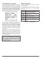
6
3. BEFORE INSTALLATION
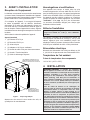
Receiving Equipment
The manufacturer recommends that this manual be
reviewed thoroughly before installing the pool/spa heater. If
there are any questions that this manual does not answer,
please contact the factory or your local representative.
On receipt of your equipment it is suggested that you
visually check for external damage to the carton. If the
carton is damaged, a note should be made on the Bill
of Lading when signing for the equipment. Remove the
heater from the carton. If it is damaged, report the damage
to the carrier immediately. Save the carton.
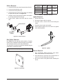
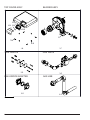
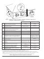
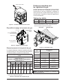
These items are shipped inside a box in the carton with
the heater:
Standard Unit
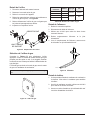
1. (2) 2" CPVC Tailpiece
2. (2) 2" CPVC Ring Nut
3. (2) O-rings
4. (1) 120V Blower Adapter
5. (1) 3-Wire Remote Harness
6. (1) Auxiliary Harness / Terminal
7. (1) Raymote Quick Start Guide
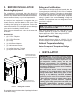
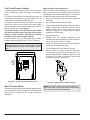
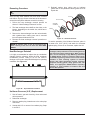
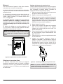
MODEL AND SERIAL NO.
LOCATED ON RATING PLATE
THE MODEL AND SERIAL NO.
CAN ALSO BE FOUND INSIDE
THE BEZEL ABOVE THE DISPLAY
Figure 1. Rating Plate Location
Be sure that you receive the number of packages indicated
on the Bill of Lading.
Rating and Certications
These heaters are design-certied and tested under the
latest requirements of the ANSI Z21.56 / CSA 4.7 Standard
for Gas-Fired Pool Heaters. This product is also certied
to SCAQMD 1146.2 and SJVAPCD Rule 4308. All heaters
can be used either indoors or outdoors when appropriate
venting is installed. See section "Venting" on page 13
for details. The appropriate vent cover designated for each
type of use is required.
Elevation
NOTE: This product is approved up to 4,500 ft of
elevation per CAN/CGA-2.17-M91.
Rated inputs are suitable for up to 4,500 feet (1371 m)
elevation. Approved up 10,000 ft for natural gas; Liquid
Propane approved to 4501-7800 ft using kit 018762F.
Required Power Supply
Requires 240VAC (factory default) or 120VAC, 1 Ph, 60
Hz Power Supply. Do not operate on 50 Hz power supply.
Ambient Temperature Rating
Heater Component Temperature Ratings
-32°F to 175°F (-35°C to 79°C).
4. INSTALLATION
AWARNING: This unit contains refractory ceramic
ber (RCF) insulation in the combustion chamber. RCF,
as manufactured, does not contain respirable crystalline
silica. However, following sustained exposure to very
high temperatures >2192°F (1200°C), the RCF can
transform into crystalline silica (cristabolite). The
International Agency for Research on Cancer (IARC) has
classied the inhalation of crystalline silica (cristabolite)
as carcinogenic to humans.
When removing the burner or heat exchanger, take
precautions to avoid creating airborne dust and avoid
inhaling airborne bers. When cleaning spills, use wet
sweeping or High Eciency Particulate Air (HEPA)
ltered vacuum to minimize airborne dust. Use feasible
engineering controls such as local exhaust ventilation
or dust collecting systems to minimize airborne dust.
Wear appropriate personal protective equipment
including gloves, safety glasses with side shields, and
appropriate NIOSH-certied respiratory protection,
to avoid inhalation of airborne dust and airborne ber
particles.

7
IMPORTANT NOTICE: These instructions are intended
only for the use by qualied personnel, specically
trained and experienced in the installation of this type
of heating equipment and related system components.
Installation and service personnel may be required by
some states to be licensed. If your state is such, be sure
your contractor bears the appropriate license. Persons
not qualied shall not attempt to x the equipment nor
attempt repairs according to these instructions.
AWARNING: Improper installation, adjustment,
alteration, service or maintenance may damage the
equipment, create a hazard resulting in asphyxiation,
explosion or re, cause damage which will not be
covered under warranty.
Installation Codes
Installation must be in accordance with local codes, or,
in the absence of local codes, with the latest edition of
the National Fuel Gas Code, ANSI Z223.1/NFPA54 and
National Electrical Code, ANSI/NFPA 70, and for Canada,
the latest edition of CAN/CSA-B149 Installation Codes,
and Canadian Electrical Code, CSA C22.1 Part 1 and
Part 2.
AAVERTISSEMENT: Cet appareil doit être installé
conformément au National Fuel gas Code ANSI Z223.1,
et aux exigences de l’autorité competente.
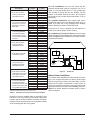
Clearances
All Heaters
For indoor and outdoor clearances from combustible
surfaces see Table B below.
Location Indoor Installation
Top Unobstructed
Front 0"
Floor 0"
Back 0"
Right Side 3" (76 mm) from Panel - Water Side
Left Side 3" (76 mm) from Panel - Vented Side
Location Outdoor Installation
Top Unobstructed
Front 0"
Floor 0"
Back 0"
Right Side 3" (76 mm) from Panel - Water Side
Left Side 6" (152 mm) from Vent Cap
Table B. Minimum Clearances from Combustible Surfaces
For ease of servicing, we recommend a clearance of at
least 24" (610 mm) for both the left and right side, and
also the top. This will enable the heater to be serviced in
its installed location, that is, without needing to move the
header.
Clearances less than these may require removal of the
heater to service either the heat exchanger or the burner.
In either case, the heater must be installed in a manner
that will enable the heater to be serviced without removing
any structure around the heater.
Flooring
This heater can be installed on combustible ooring.
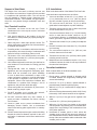
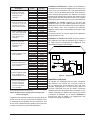
Outdoor Heater Installation
These heaters are design-certied for outdoor installation,
when equipped with the approved vent cover designated
for outdoor use.
AWARNING: The heater shall not be located in an
area where water sprinklers, or other devices, may cause
water to spray through the cabinet louvers and into the
heater. This could cause internal rusting or damage
electrical components, and void the warranty.
AWARNING: Do not install within 3' (0.9 m) of a heat
pump or an outdoor condensing unit. Strong air intake
from this type of equipment can disturb the combustion
process and cause damage or personal injury.
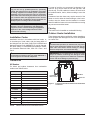
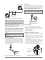
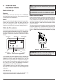
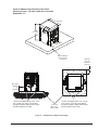
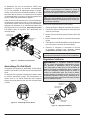
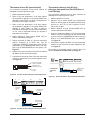
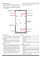
OUTDOOR
VENT COVER
INLET
OUTLET
Figure 2. Front View Of Cabinet Vent/Air Inlet Termination
Clearances

8
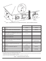
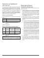
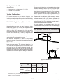
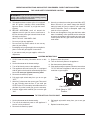
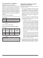
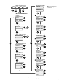
U.S. Installations1Canadian Installations 2
AClearance above grade, veranda, porch, deck, or
balcony 1' (30 cm) 1' (30 cm)
B Clearance to window or door that may be opened 4' (1.2 m) below or to side of
opening 3' (91 cm)
C Clearance to permanently closed window * *
D
Vertical clearance to ventilated sot located above the
terminal within a horizontal distance of 2' (61 cm) from
the centerline of the terminal
5' (1.5 m) *
EClearance to unventilated sot * *
FClearance to outside corner * *
G Clearance to inside corner 6' (1.83 m) *
HClearance to each side of center line extended above
meter/regulator assembly *3' (91 cm) within a height
15' (4.5 m) above the meter/
regulator assembly
I Clearance to service regulator vent outlet *6' (1.83 m)
J
Clearance to non-mechanical air supply inlet to
building or the combustion air inlet to any other
appliance
4' (1.2 m) below or to side of
opening; 1' (30 cm) above
opening
3' (91 cm)
KClearance to mechanical air supply inlet 3' (91 cm) above if within
10' (3 m) horizontally 6' (1.83 m)
LDo not terminate above paved sidewalk or paved
driveway
Slip hazard due to frozen
condensate
Slip hazard due to frozen
condensate
MClearance under veranda, porch, deck or balcony *1' (30 cm)t
1 In accordance with the current ANSI Z223.1/NFPA 54 National Fuel Gas Code.
2 In accordance with the current CAN/CSA-B149 Installation Codes.
t Permitted only if veranda, porch, deck, or balcony is fully open on a minimum of two sides beneath the floor and top of terminal, and underside
of veranda, porch, deck or balcony is greater than 1' (30 cm).
* Clearances in accordance with local installation codes and the requirements of the gas supplier.
A
INSIDE
CORNER DETAIL
V = VENT
X = AIR INLET
F10692
V
G
H
A
B
B
V
V
B
BV
AJ
XIM
VX
K
V
V
B
F
C
OPERABLE FIXED
CLOSED
FIXED
CLOSED
OPERABLE
Table C. Vent/Air Inlet Termination Clearances
Figure 3. Minimum Clearances from Vent/Air Inlet Terminations – Indoor and Outdoor Installations

9
Description Location Distance
in. (mm)
a. 3-1/2" (89 mm) thick
masonry walls without
ventilated air space
Back 9 (229)
Right 9 (229)
Left 9 (229)
Vent 5 (127)
Indoor Top 39 (991)
Outdoor Top Unobstructed
b. 1/2" (13 mm) insulation
board over 1" (25 mm)
glass ber or mineral
wool batts
Back 6 (152)
Right 6 (152)
Left 6 (152)
Vent 3 (76)
Indoor Top 30 (762)
Outdoor Top Unobstructed
c. 0.024 sheet metal over
1" (25 mm) glass ber
or mineral wool batts
reinforced with wire on
rear face with ventilated
air space
Back 4 (102)
Right 4 (102)
Left 4 (102)
Vent 3 (76)
Indoor Top 24 (610)
Outdoor Top Unobstructed
d. 3-1/2" (89 mm) thick
masonry wall with
ventilated air space
Back 6 (152)
Right 6 (152)
Left 6 (152)
Vent 6 (152)
Indoor Top 39 (991)
Outdoor Top Unobstructed
e. 0.024 sheet metal with
ventilated air space
Back 4 (102)
Right 4 (102)
Left 4 (102)
Vent 2 (51)
Indoor Top 24 (610)
Outdoor Top Unobstructed
f. 1/2" (13 mm) thick
insulation board with
ventilated air space
Back 4 (102)
Right 4 (102)
Left 4 (102)
Vent 3 (76)
Indoor Top 24 (610)
Outdoor Top Unobstructed
g. 0.024 sheet metal with
ventilated air space over
0.024 sheet metal with
ventilated air space.
Back 4 (102)
Right 4 (102)
Left 4 (102)
Vent 3 (76)
Indoor Top 24 (610)
Outdoor Top Unobstructed
h. 1" (25 mm) glass ber
or mineral wool batts
sandwiched between two
sheets 0.024 sheet metal
with ventilated air space
Back 4 (102)
Right 4 (102)
Left 4 (102)
Vent 3 (76)
Indoor Top 24 (610)
Outdoor Top Unobstructed
Derived from National Fuel Gas Code, Table 10.2.3
Table D. Reduction of Clearances to Protected Surfaces
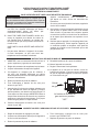
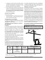
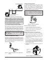
Heaters must not be installed under an overhang of less
than three 3' (0.9 m) from the top of the heater. Three sides
must be open in the area under the overhang. Roof water
drainage must be diverted away from the heaters installed
under overhangs with the use of gutters.
For U.S. installations, the point from where the ue
products exit the heater must be a minimum of 4' (1.2 m)
below, 4' (1.2 m) horizontally from, or 1' (0.3 m) above any
door, window or gravity inlet into any building. The top
surface of the heater shall be at least 3' (0.9 m) above
any forced air inlet, or intake ducts located within 10' (3 m)
horizontally.
For Canadian installations, pool heaters shall not be
installed with the top of the vent assembly within 10' (3 m)
below, or to either side, of any opening into the building.
Refer to the latest revisions of CAN/CSA-B149.
A minimum of 6' (1.8 m) is required from the heater to an
inside corner wall for proper outdoor venting.
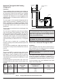
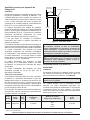
For installations in Florida and Texas, that must comply
with the Florida or Texas Building Code, follow the directions
shown in Figure 5 for the installation of hurricane tie-down
brackets for all models.
4' (1.2 m)
MIN
4' (1.2 m)
MIN
4' (1.2 m)
MIN
3' (0.9 m)
MIN
10' (3 m)
MIN
4' (1.2 m)
MIN
FORCED AIR
INLET
Figure 4. Clearances
Indoor Heater Installation
For Canada, indoor installation is restricted to an enclosure
that is not occupied and does not directly communicate
with an occupied area. Refer to the latest edition of CAN/
CSA-B149 for specic requirements. Locate heater as
close as is practical to a chimney or gas vent. Heater must
always be vented to the outside. See "Venting" section on
page 13 for details. Minimum allowable space is shown
on the nameplate.

10
Combustion and Ventilation Air
Indoor Units Only
The heater must have both combustion and ventilation
air. The minimum requirements are listed in the latest
edition of the National Fuel Gas Code (U.S. ANSI Z223.1
or Canada CAN/CSA-B149) and any local codes that
may have jurisdiction. The most common approach is
the “2-opening” method, with combustion air opening no
more than 12" (305 mm) from the oor and the ventilation
opening no more than 12" (305 mm) from the ceiling. For
opening sizes using this method, see below.
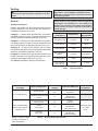
All Air from Inside the Building:
Each opening shall have a minimum net free area as
noted:
Model Sq. in. (m²)
264 264 (0.17)
404 399 (0.26)
Table E. Opening Minimum Net Free Requirements -
Indoor Air
All Air from Outdoors:
When air is supplied directly from outside the building, each
opening shall have a minimum net free area as noted:
Model
Unrestricted
Opening
sq. in. (m²)
Typical Screened
or Louvered
Opening
sq. in. (m²)
Typical Screened
and Louvered
Opening
sq. in. (m²)
264 66 (0.04) 99 (0.06) 132 (0.09)
404 100 (0.06) 150 (0.1) 200 (0.13)
Table F. Opening Minimum Net Free Requirements -
Outdoor Air
ACAUTION: Combustion air must not be contaminated
by corrosive chemical fumes which can damage the
heater. Such damage will not be covered by the warranty
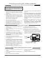
Direct Vent and Ducted
Combustion Air Systems
If outside air is drawn through the intake pipe directly to the
unit for combustion:
1. Connect combustion air to the heater by removing
the screened cap on the air intake port, and sealing
the combustion air duct to the existing PVC adapter.
Glue or attach screws to fasten. The existing screen
should be re-used at the intake end of the duct. Install
the combustion air duct in accordance with Figure
11 or Figure 12 of this manual.
2. Provide adequate ventilation of the space occupied
by the heater(s) by an opening(s) for ventilation air
at the highest practical point communicating with the
outdoors.
A. In the US, the total cross-sectional area shall be
at least 1 in.² of free area per 20,000 BTUH (111
mm² per kW) of total input rating of all equipment
in the room when the opening is communicating
directly with the outdoors or through vertical
duct(s). The total cross-sectional area shall be at
least 1 in.² of free area per 10,000 BTUH (222
mm² per kW) of total input rating of all equipment
in the room when the opening is communicating
with the outdoors through horizontal duct(s).
B. In Canada, there shall be permanent air supply
opening(s) having a total cross-sectional area of
not less than 1 in.² of free area per 30,000 BTUH
(70 mm² per kW) of the total rated input. The
location of the opening(s) shall not interfere with
the intended purpose of the opening(s) for the
ventilation air.
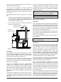
3. In cold climates, and to mitigate potential freeze-
up, Raypak highly recommends the installation of a
motorized sealed damper to prevent the circulation of
cold air through the heater during the non-operating
hours.

11
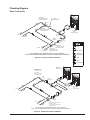
29" (73.6 cm)
3" (76 mm)
Min. Conc.
Pad by others
3" (76 mm)
Min. Conc.
Pad by others
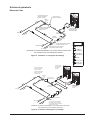
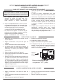
(1)–1/4" x 2-1/4" S.S. Tapcon
Bolt & Washer (Field-Supplied)
Ea. Pallet Anchor Bracket
Use hole closest to unit (4 total)
(1)–1/4" x 2-1/4" S.S.
Tapcon Bolt & Washer (Field-Supplied)
Ea. Pallet Anchor Bracket
Use hole closest to unit (4 total)
Min. Edge
Distance
6"
(152 mm)
Min. Edge
Distance
6"
(152 mm)
16.92"
(43.0 cm)
30.38"
(77.1 cm)
Florida and Texas Building Code:
Wind Speed = 180 mph 3-sec. gust
Exposure = C
Figure 5. Hurricane Tie-Down Bracket Installation

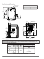
12
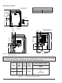
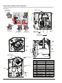
Model No.
BTUH
Input
(kw)
Flue
Dia.
in. (mm)
Water
Conn.
in. (mm)
Shipping Weights - lbs (kg)
Standard
Heater
264 264
(77.4) 4
(101.6)
2 (51)
Buttress
135
(61.2)
+20 (9) Packing
404 399
(116.9)
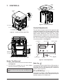
Table G. Heater Specications and Dimensions
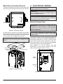
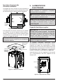
Specications and Dimensions
Figure 6. Front View
5.61”
(143 MM)
10.14”
(258 MM)
23.24”
(590 MM)
14.63”
(372 MM)
30.38”
(772 MM)
CONTROL DISPLAY
AND INTERFACE
OUTDOOR FLUE
COVER
F10815
Water Inlet
Water Outlet
KNOCKOUT FOR 4”
COMBUSTION AIR DUCT
6.89”
(175 mm)
22.64”
(575 mm)
4.53”
(115 mm)
10.86”
(276 mm) 23.22”
(590 mm)
30.38”
(772 mm)
F10816
Amp Draw
120 VAC, 1 Ph, 60 Hz 240 VAC, 1 Ph, 60 Hz
1.6A 1.2A
Figure 7. Left View with Gas & Power Connection
Distances
WARNING: The Commonwealth of Massachusetts requires that sidewall-vented heaters, installed in every
dwelling, building or structure used in whole or in part for residential purposes, be installed using special provi-
sions as outlined on page 93 of this manual.
5.99”
(150 mm)
4.63”
(116 mm)
3/4”
(19 mm)
NPT Gas
16.02”
(406 mm)
12.98”
(330 mm)
Figure 8. Right View

13
Venting
ACAUTION: Proper installation of ue venting is
critical for the safe and ecient operation of the pool
heater.
General
Appliance Categories
Heaters are divided into four categories based on the
pressure produced in the exhaust and the likelihood of
condensate production in the vent.
Category I – A heater which operates with a non-positive
vent static pressure and with a vent gas temperature that
avoids excessive condensate production in the vent.
Category II – A heater which operates with a non-positive
vent static pressure and with a vent gas temperature that
may cause excessive condensate production in the vent.
Category III – A heater which operates with a positive
vent pressure and with a vent gas temperature that avoids
excessive condensate production in the vent.
Category IV – A heater which operates with a positive vent
pressure and with a vent gas temperature that may cause
excessive condensate production in the vent.
See Table H for appliance category requirements.
Combustion
Air Supply Exhaust Conguration Heater Venting
Category Certied Vent Materials Combustion Air
Inlet Material
From Inside Building
Vertical Venting I
Fan
B-Vent
Equivalent
Horizontal Through-the-Wall
Venting III
UL 1738
Metallic Vent
(such as AL29-4C)
From Outside Building
(Direct Vent or Ducted
Combustion Air)
Vertical Venting with Ducted
Combustion Air
I
Fan
B-Vent
Equivalent
Galvanized Steel,
PVC, ABS,
CPVC
Vertical
Direct Vent III
UL 1738
Metallic Vent
(such as AL29-4C)
Horizontal
Direct Vent III
UL 1738
Metallic Vent
(such as AL29-4C)
Table H. Venting Category Requirements
NOTE: For additional information on appliance
categorization, see the ANSI Z21.13 Standard and the
NFGC (U.S.), or B149 (Canada), or applicable provisions
of local building codes.
AWARNING: Contact the manufacturer of the vent
material if there is any question about the appliance
categorization and suitability of a vent material for
application on a Category I vent system. Using improper
venting materials can result in personal injury, death or
property damage.
Description
(Terminations) Manufacturer Manufacturer
Model Number
Through-the-wall Duravent FSTB4
Horizontal Tee Duravent FSTT4
Horizontal Tee Z-Flex 2SVSTTF04
Wall Thimble with
Damper Duravent PRTFSWTT4
90-degree Elbow Z-Flex 2SVSTEX0490
D15 - Vertical
Horizontal Cap Raypak 014289
Table I. Vent Terminations
Note: For appliance adapter
use Duravent FSAAU4 or
Z-Flex 2SVSNA04.5

14
Support of Vent Stack
The weight of the vent stack or chimney must not rest
on the heater vent connection. Support must be provided
in compliance with applicable codes. The vent should
also be installed to maintain proper clearances from
combustible materials. Use insulated vent pipe spacers
where the vent passes through combustible roofs and
walls.
Vent Terminal Location
1. Condensate can freeze on the vent cap. Frozen
condensate on the vent cap can result in a blocked
flue condition.
2. Give special attention to the location of the vent
termination to avoid possibility of property damage or
personal injury.
3. Gases may form a white vapor plume in winter. The
plume could obstruct a window view if the termination
is installed near windows.
4. Prevailing winds, in combination with below-freezing
temperatures, can cause freezing of condensate and
water/ice build-up on buildings, plants or roofs.
5. The bottom of the vent terminal and the air intake
shall be located at least 12 in. (305 mm) above grade,
including normal snow line.
6. Un-insulated single-wall metal vent pipe shall not be
used outdoors in cold climates for venting gas-fired
equipment.
7. Through-the-wall vents for Category II and IV
appliances and non-categorized condensing appli-
ances shall not terminate over public walkways
or over an area where condensate or vapor could
create a nuisance or hazard or could be detrimental
to the operation of regulators, relief valves, or other
equipment. Where local experience indicates that
condensate is a problem with Category I and III
appliances, this provision shall also apply.
8. Locate and guard vent termination to prevent acci-
dental contact by people or pets.
9. DO NOT terminate vent in window well, stairwell,
alcove, courtyard or other recessed area.
10. DO NOT terminate above any door, window, or
gravity air intake. Condensate can freeze, causing
ice formations.
11. Locate or guard vent to prevent condensate from
damaging exterior finishes. Use a rust-resistant
sheet metal backing plate against brick or masonry
surfaces.
12. DO NOT extend exposed vent pipe outside of building
beyond the minimum distance required for the vent
termination. Condensate could freeze and block the
vent pipe.
U.S. Installations
Refer to the latest edition of the National Fuel Gas Code.
Vent termination requirements are as follows:
1. Vent must terminate at least 4 ft (1.2 m) below, 4 ft
(1.2 m) horizontally from or 12 in. (305 mm) above
any door, window or gravity air inlet to the building.
2. The vent must not be less than 7 ft (2.1 m) above
grade when located adjacent to public walkways.
3. Terminate vent at least 3 ft (0.9 m) above any forced
air inlet located within 10 ft (3.0 m).
4. Vent must terminate at least 4 ft (1.2 m) horizontally,
and in no case above or below, unless a 4 ft (1.2
m) horizontal distance is maintained from electric
meters, gas meters, regulators, and relief equipment.
5. Terminate vent at least 6 ft (1.8 m) away from adjacent
walls.
6. DO NOT terminate vent closer than 5 ft (1.5 m) below
roof overhang.
7. The vent terminal requires a 12 in. (305 mm) vent
terminal clearance from the wall.
8. Terminate vent at least 12 in. (305 mm) above grade,
including normal snow line.
9. Multiple direct vent installations require a 4 ft (1.2 m)
clearance between the ends of vent caps located on
the same horizontal plane.
Canadian Installations
Refer to latest edition of the B149 Installation code.
A vent shall not terminate:
1. Directly above a paved sidewalk or driveway which
is located between two single-family dwellings and
serves both dwellings.
2. Less than 7 ft (2.13 m) above a paved sidewalk or
paved driveway located on public property.
3. Within 6 ft (1.8 m) of a mechanical air supply inlet to
any building.
4. Above a meter/regulator assembly within 3 ft (915 mm)
horizontally of the vertical centerline of the regulator.
5. Within 3 ft (0.9 m) of any gas service regulator vent
outlet.
6. Less than 12 in. (305 mm) above grade level.
7. Within the 3 ft (915 mm) of a window or door which
can be opened in any building, any non-mechanical air
supply inlet to any building or the combustion air inlet
of any other appliance.
8. Underneath a veranda, porch or deck, unless the
veranda, porch or deck is fully open on a minimum of
two sides beneath the floor, and the distance between
the top of the vent termination and the underside of the
veranda, porch or deck.

15
Venting Installation Tips
Support piping:
• horizontal runs—at least every 5 ft (1.5 m)
• vertical runs—use braces
• under or near elbows
Venting Congurations
For heaters connected to gas vents or chimneys, vent
installations shall be in accordance with the NFGC (U.S.),
or B149 (Canada), or applicable provisions of local building
codes.
Vertical Venting (Category I) Fan-Assisted
Installation
Natural draft venting uses the natural tendency of the
heated ue gases to rise, until they are expelled from the
top of the ue. The negative draft must be within the range
of -.01 to -.08 in. WC as measured 12 in. (305 mm) above
the appliance ue outlet to ensure proper operation. Vent
material must be listed by a nationally recognized test
agency.
Double-wall Type B vent must be used to promote draft
and to minimize condensation in the vent.
No drafthood is required or oered. A single-acting
barometric damper is required if the height exceeds 25
feet (7.6 m).
The connection from the appliance vent to the stack must
be as direct as possible. The horizontal breaching of a
vent must have an upward slope of not less than 1/4 inch
per linear foot from the heater to the vent terminal. The
horizontal portions of the vent shall also be supported for
the design and weight of the material employed to maintain
clearances and to prevent physical damage or separation
of joints.
Termination
The vent terminal should be vertical and should terminate
outside the building at least 2 ft (0.6 m) above the highest
point of the roof that is within 8 ft (2.4 m). The vent cap
should have a minimum clearance of 4 ft (1.2 m) horizontally
from and in no case above or below electric meters, gas
meters, regulators and relief equipment, unless a 4 ft (1.2
m) horizontal distance is maintained. The distance of the
vent terminal from adjacent public walkways, adjacent
buildings, open windows and building openings must be
consistent with the NFGC (U.S.) or B149 (Canada). Gas
vents supported only by ashing and extended above the
roof more than 5 ft (1.5 m) should be securely guyed or
braced to withstand snow and wind loads.
For factory approved vent termination caps, refer to the
Illustrated Parts List (IPL) section of this manual. See page
84.
CAUTION: A listed vent cap terminal adequately sized,
must be used to evacuate the ue products from the
building.
HEATER
8' OR LESS
(2.4 m)
2' MIN
(0.6 m) 2' MIN
(0.6 m)
VENT CAP
Figure 9. Vertical Venting
Model
No.
Certied
Vent
Material
Vent Size
in. (mm)
Vertical Vent Height
ft (m)*
Min. Max.
264/404
Category I
(Type B
Equivalent)
Fan-Assisted
4 (101.6) 5 (1.5) 25 (7.6)
Vent lengths are based on a lateral length of 2 ft (0.6 m). Refer to the latest edition of the NFGC for further details. When vertical height
exceeds 25 ft (7.6 m), consult factory prior to installation.
*Subtract 12 ft (3.6 m) per elbow.
Table J. Category I Vertical Venting

16
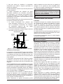
Horizontal Through-the-Wall Venting
(Category III)
Installation
These installations utilize the heater’s internal blower to
vent the combustion products to the outdoors. Combustion
air is taken from inside the room and the vent is installed
horizontally through the wall to the outdoors. Adequate
combustion and ventilation air must be supplied to the
equipment room in accordance with the NFGC (U.S.) or
B149 (Canada).
The total length of the horizontal through-the-wall ue
system should not exceed 75 equivalent ft (22.86 m) in
length. If horizontal run exceeds 75 equivalent ft (22.86
m), an appropriately-sized variable-speed extractor must
be used. Each elbow used is equal to 12 ft (3.6 m) of
straight pipe.
The vent cap is not considered in the overall length of the
venting system.
The vent must be installed to prevent ue gas leakage.
Care must be taken during assembly to ensure that all
joints are sealed properly and are airtight. The vent must
be installed to prevent the potential accumulation of
condensate in the vent pipes. It is recommended that the
vent be insulated. Insulation is required for installations in
cold environments (i.e. below 40°F or 4°C). It is required
that:
The vent must be installed with a condensate drain
located in proximity to the heater as directed by the vent
manufacturer.
The vent must be installed with a slight upward slope of
not less than 1/4 inch per foot of horizontal run to the vent
terminal.
Termination
The vent cap MUST be mounted on the exterior of the
building. The vent cap cannot be installed in a well or
below grade. It must be installed at least 12" (305 mm)
above ground level and above normal snow levels. The
vent terminal must be located NO CLOSER than 12" (305
mm) o the wall.
For factory approved vent termination caps, refer to the
Illustrated Parts List (IPL) section of this manual. See
page 84.
INSULATED EXHAUST
VENTING
FLUE EXHAUST
VENT CAP
HEATER
12" MIN
(305 mm)
12" MIN
(305 mm)
CONDENSATION
TRAP
Figure 10. Horizontal Through-the-Wall Venting
CAUTION: This venting system requires the installation
of a condensate drain in the vent piping per the vent
manufacturer's instructions. Failure to install a condensate
drain in the venting system will cause damage which will
not be covered under warranty.
AWARNING: No substitutions of ue pipe or vent
cap material are allowed. Such substitutions would
jeopardize the safety and health of inhabitants.
Direct Vent - Horizontal Through-the-Wall
Installation
These installations utilize the heater’s internal blower to
draw combustion air from outdoors and vent combustion
products to the outdoors, see Table K.
NOTE: Use of B-vent on such a system does not meet
direct-vent requirements.
The exhaust and intake systems must be installed to
prevent the potential accumulation of condensate. It is
recommended that they be insulated. Insulation is required
for installations in cold environments (i.e. below 40°F (4°C).
The ue termination cap is not considered in the overall
length of the venting system.
Model
No.
Certied
Vent
Material
Vent
Size
ft (m)
Maximum
Vent Length
ft (m)*
Combustion Air Intake
Pipe Material**
Air Intake Max. Length*
ft (m)
4" Ø
264/404 Category III 4 (1.2) 75 (22.86)
Galvanized Steel,
PVC,
ABS,
CPVC
75 (22.86)
* Subtract 12 ft (3.6 m) per elbow.
** Schedule 40 in PVC or CPVC.
Table K. Category III Horizontal Vent & Horizontal Direct Vent

17
Care must be taken during assembly that all joints are
sealed properly and are airtight.
The vent must be installed to prevent the potential
accumulation of condensate in the vent pipes. It is
recommended that the vent be insulated. Insulation is
required for installations in cold environments (i.e., below
40°F or 4°C).
For installations in extremely cold climates, it is required
that:
1. The vent must be installed with a slight upward slope
of not more than 1/4 inch per foot of horizontal run to
the vent terminal. An approved condensate trap must
be installed per applicable codes.
2. The air intake vent must be insulated through the
length of the horizontal run.
HEATER
12" MIN
(305 mm)
CONDENSATION
TRAP
AIR
INTAKE
ALTERNATE COMBUSTION
AIR INTAKE LOCATION
HORIZONTAL
TERMINATION CAP (D-15) INSULATED EXHAUST
VENTING
12” MIN
(305 mm)
6” MIN
(153 mm)
36” MIN
(915 mm)
12” MIN
(305 mm)
Figure 11. Horizontal Through-the-Wall Direct Venting
Termination
The exhaust vent cap MUST be mounted on the exterior
of the building, and cannot be installed in a well or below
grade. It must be installed at least 12" (305 mm) above
ground level and above normal snow levels.
The exhaust vent cap MUST NOT be installed below or
closer than 3 ft (0.9 m) from the air intake. Venting any
closer to the air intake will cause combustion gases to
recirculate into the heater.
This type of installation can cause non-warrantable
problems with components and poor operation of the
heater due to the recirculation of ue products. Multiple
vent caps should be installed in the same horizontal plane
with a 4 ft (1.2 m) minimum clearance from the side of
one vent cap to the side of the adjacent vent cap(s). See
Figure 11.
Combustion air supplied from outdoors must be free of
particulate and chemical contaminants. To avoid a blocked
ue condition, keep the vent cap clear of snow, ice, leaves,
debris, etc.
Use only the special gas vent pipes listed for use with
Category III gas burning heaters, such as the AL29-
4C stainless steel vents oered by DuraVent (www.
duravent.com). Follow the vent manufacturer’s installation
instructions carefully.
AWARNING: No substitutions of ue pipe or vent
cap material are allowed. Such substitutions would
jeopardize the safety and health of inhabitants.
ACAUTION: Condensate is acidic and highly corrosive.
Direct Vent—Vertical
Installation
These installations utilize the heater-mounted blower to
draw combustion air from outdoors and force the heated
ue products through the vent pipe under positive pressure.
The vent material must be in accordance with the above
instructions for vent materials. Vent material must be listed
by a nationally recognized test agency.
The connection from the appliance ue to the stack must
be as direct as possible and should be the same size or
larger than the vent outlet.
It is recommended that the intake vent be insulated in
colder climates.
NOTE: Use of B-vent on such a system does not meet
direct-vent requirements.
Termination
The ue should be vertical and should terminate outside
the building at least 2 ft (0.6 m) above the highest point
of the roof within 10 ft (3.0 m). The vent cap should have
a minimum clearance of 4 ft (1.2 m) horizontally from
and in no case above or below (unless a 4 ft (1.2 m))
horizontal distance is maintained) electric meters, gas
meters, regulators and relief equipment. The distance of
the vent terminal from adjacent public walkways, adjacent
buildings, open windows and building openings must be
consistent with the NFGC (U.S.) or B149 (Canada).
Vent pipes supported only by ashing and extended above
the roof more than 5 ft (1.5 m) should be securely guyed or
braced to withstand snow and wind loads.
The air inlet opening MUST be installed 1 ft (305 mm)
above the roof line or above normal snow levels that might
obstruct combustion air ow. This dimension is critical to
the correct operation of the heater and venting system and
reduces the chance of blockage from snow. The vent cap
must have a minimum 3 ft (0.9 m) vertical clearance from
the air inlet opening.
Use only the special gas vent pipes listed for use with
Category III gas burning heaters, such as the AL29-4C
stainless steel vents oered by DuraVent (www.duravent.
com). Pipe joints must be positively sealed. Follow the
vent manufacturer’s installation instructions carefully.

18
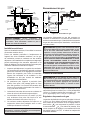
Gas Supply Connections
GAS VALVE
HEATER
JACKET
3" MIN
(7.6 cm)
TYPICAL
FIELD-SUPPLIED
SEDIMENT
TRAP
UNION
GAS
SUPPLY
INLET MANUAL
SHUTOFF
VALVE
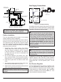
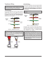
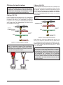
Figure 13. Gas Supply Plumbing
Gas piping must have a sediment trap ahead of the heater
gas controls, and a manual shuto valve located outside
the heater jacket. All gas piping should be tested after
installation in accordance with local codes.
ACAUTION: The heater and its manual shuto valve
must be disconnected from the gas supply during any
pressure testing of that system at test pressures in
excess of 1/2 psi (3.45 kPa). Dissipate test pressure in
the gas supply line before reconnecting the heater and
its manual shuto valve to gas supply line. FAILURE
TO FOLLOW THIS PROCEDURE MAY DAMAGE THE
GAS VALVE. OVER-PRESSURIZED GAS VALVES ARE
NOT COVERED BY WARRANTY. The heater and its gas
connections shall be leak-tested before placing the
appliance in operation. Use soapy water for leak test. DO
NOT use open ame.
Supply Pressure
ACAUTION: Do not use Teon tape on gas line pipe
thread. Only sealant tape or a pipe compound rated for
use with natural and propane gases is recommended.
Apply sparingly only on male pipe ends, leaving the two
end threads bare.
A minimum of 3.5 in. WC and a maximum of 10.5 in. WC
upstream pressure under load and no-load conditions
must be provided for natural gas. Required pressure for
Propane Gas: Min = 8.0" WC (Dynamic), Max = 13" WC
(Static).
Gas Pressure Regulator
The gas manifold pressure is preset to a negative -0.30"
WC. If an adjustment is needed, remove the gas valve
throttle seal and turn adjustment screw clockwise to
increase pressure or counter-clockwise to decrease
pressure. If available, the O2 must be within 4.5 - 5.5%
using a calibrated combustion analyzer.
ALTERNATE COMBUSTION
AIR INTAKE LOCATION
INTAKE VENT
INSULATED
EXHAUST VENTING
HEATER
VERTICAL VENT
CAP TERMINATION 3’ MIN
(915 MM)
3’ MIN
(915 MM) 1’ MIN
(305 MM)
6” MIN
(153 MM)
12” MIN
(304 MM)
Figure 12. Direct Vent - Vertical
AWARNING: No substitutions of vent pipe or vent
cap material are allowed. Such substitutions would
jeopardize the safety and health of inhabitants.
Outdoor Installation
The vent cap provided with the heater is the standard
venting method for outdoor installations.
Care must be taken when locating the heater outdoors,
because the ue gases discharged from the vent cap
can condense as they leave the cap. Improper location
can result in damage to adjacent structures or building
nish. For maximum eciency and safety, the following
precautions must be observed:
1. Periodically check venting system. The heater’s
venting areas must never be obstructed in any
way and minimum clearances must be observed
to prevent restriction of combustion and ventilation
air. Keep area clear and free of combustible and
flammable materials.
2. Do not locate adjacent to any window, door, walk-
way, or gravity air intake. The vent must be located a
minimum of 4 ft (1.2 m) horizontally from such areas.
3. Install above grade level and above normal snow
levels.
4. Vent terminal must be at least 3 ft (0.9 m) above any
forced air inlet located within 10 ft (3.0 m).
5. Adjacent brick or masonry surfaces must be protected
with a rust-resistant sheet metal plate.
NOTE: Condensate can freeze on the vent cap. Frozen
condensate on the vent cap can result in a blocked ue
condition.

19
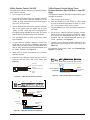
MANUAL
SHUTOFF
VALVE
UNION
F10817
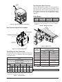
Figure 14. Manual Shuto Valve Installation
Gas Pressure Adjustment Locations
CAP
ADJUSTMENT SCREW INSIDE
CLOCKWISE TO INCREASE
GAS VALVE
SUPPLY PRESSURE
TAP ON INLET SIDE
GAS FLOW
MANIFOLD
PRESSURE TAP
Figure 15. Gas Valve Adjustment
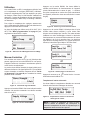
Pipe Sizing for Gas Connection
The capacities shown below are based on using SCH
40 black iron pipe. For capacities using other materials,
consult local codes.
Maximum Equivalent Pipe Length
ft (m)
Natural Gas 1000 BTU/FT³ 0.60 Specic Gravity @ 0.5 in.
WC Pressure Drop
Propane Gas 2500 BTU/FT³ 1.53 Specic Gravity @ 0.5 in
WC Pressure Drop
Model
No.
Size 3/4" Size 1" Size 1-1/4" Size 1-1/2"
NAT PRO NAT PRO NAT PRO NAT PRO
264 15
(4.6)
35
(10.7)
50
(12.2)
125
(38.1)
210
(64.0)
480
(146.3)
445
(135.6)
404 *15
(4.6)
20
(8.8)
55
(16.8)
95
(29.0)
225
(68.6)
215
(65.5)
280
(85.3)
* A 3/4" gas line can be used for up to 5' (1.5 m) maximum length from
the gas valve in addition to the sediment trap.
Table L. Gas Pipe Sizing
Gas Regulator Best Practices
From the gas pressure regulator, it is recommended to
have no less than 10 pipe diameters of straight smooth
pipe downstream of the regulator discharge and to have
no less than 10 linear feet (not including ttings) between
the regulator and the inlet to the appliance for proper
operation.
Flow Rates
Model Pipe Size
in. (mm) Min. GPM (lpm) Max. GPM (lpm)
264/404 2 (50.8) 40 (151) 100 (379)
* When flow rates exceed maximum GPM an external auxiliary bypass
valve is required. See External Bypass Valve Section on page 21
for details.
Table M. Min/Max Flow Rates
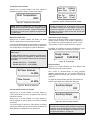
F10818
Figure 16. Water Flow
Flow
GPM (lpm)
Pressure Drop
Ft. of Head (m of Head)
264 404
40 (151) 7.2 (2.2) 13.4 (4.1)
50 (189) 10.0 (3.1) 16.5 (5.0)
60 (227) 12.6 (3.8) 19.5 (5.9)
70 (265) 17.0 (5.2) 23.7 (7.2)
80 (303) 24.0 (7.3) 28.3 (8.6)
90 (341) 30.3 (9.2) 33.2 (10.1)
100 (379) 36.0 (10.9) 37.0 (11.3)
Table N. Heat Exchanger Pressure Drops
NOTE: Table capacity is based on 2" Schedule 40 piping.

20
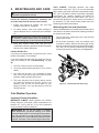
ACAUTION: Do not use tools to remove (twist) the
ProTek Shield Assy or the wing nut on the stud of the
ProTek Shield Assy. Non-warrantable damage may
occur.
Follow the steps below to replace the ProTek Shield Assy:
1. Shut off the pool pump and bleed pressure from the
system.
2. Close isolation valves to minimize pool/spa water
loss.
3. Remove wing nut from bottom stud on ProTek Shield
Assy.
4. Remove bonding wire ring terminal from stud.
5. Rotate ProTek Shield Assy counter-clockwise (by
hand) to unscrew it from the assembly.
6. Inspect/replace as necessary and reverse above
procedure to reinstall. Hand tighten only! Do not
use tools.
NOTE: Make sure the O-ring is properly seated in the
O-ring groove before installation.
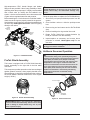
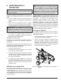
Unitherm Governor Operation
ACAUTION: The patented Unitherm Governor is
a thermostatic mixing valve specically designed to
maintain constant heater internal temperature between
120°F (49°C) and 135°F (57°C) despite continually
changing ow rates from the lter and changing pool
temperatures. This range is needed to reduce the
amount of condensation from the n tubes which will
occur if the heater runs for any length of time below
100°F (38°C) water from the pool. It is also needed to
inhibit scale formation in the tubes by maintaining
temperatures well below accelerated scaling
temperatures.
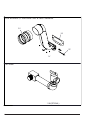
GASKET
UNITHERM
GOVERNOR
UG PLUG
UG PLUG O-RING
Figure 19. Unitherm Governor
High-temperature CPVC header anges and header
ange nuts are provided. If there is any possibility of back-
siphoning when the pump stops, it is highly recommended
that a check valve (or valves) also be installed in the
system. It is also recommended to have a downstream ball
or gate valve to regulate heater ow and pressure.
Before attaching the 2-inch unions to the inlet/Out header,
make sure the O-rings are properly seated in the grooves.
Use Aqualube or equivalent non-petroleum-based lubricant
on the O-ring. Hand tighten the unions. Glue PVC piping
directly to the unions.
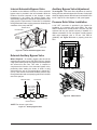
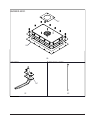
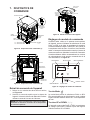
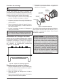
OUTLET
WATER
SENSOR
WATER
PRESSURE
SWITCH
HEADER
INLET
WATER
SENSOR
PROTEK
SHIELD
ASSY
Figure 17. Inlet/Outlet Header
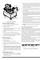
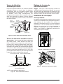
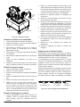
ProTek Shield Assembly
This heater is equipped with a ProTek Shield Assembly
located horizontally on the right side of the Inlet water
connection.
This component provides protection to the heat exchanger
against galvanic corrosion, when properly bonded to the
heat exchanger. It should be replaced when the weight of
the ProTek Shield is reduced to about 40% of the original
weight (1.46 lbs.).
F10715
Figure 18. ProTek Shield Assembly
ACAUTION: STOP the pool pump before attempting
to remove ProTek Shield Assembly. Failure to do so may
result in damage to ProTek Shield Assy, loss of pool
water, or personal injury.
La page est en cours de chargement...
La page est en cours de chargement...
La page est en cours de chargement...
La page est en cours de chargement...
La page est en cours de chargement...
La page est en cours de chargement...
La page est en cours de chargement...
La page est en cours de chargement...
La page est en cours de chargement...
La page est en cours de chargement...
La page est en cours de chargement...
La page est en cours de chargement...
La page est en cours de chargement...
La page est en cours de chargement...
La page est en cours de chargement...
La page est en cours de chargement...
La page est en cours de chargement...
La page est en cours de chargement...
La page est en cours de chargement...
La page est en cours de chargement...
La page est en cours de chargement...
La page est en cours de chargement...
La page est en cours de chargement...
La page est en cours de chargement...
La page est en cours de chargement...
La page est en cours de chargement...
La page est en cours de chargement...
La page est en cours de chargement...
La page est en cours de chargement...
La page est en cours de chargement...
La page est en cours de chargement...
La page est en cours de chargement...
La page est en cours de chargement...
La page est en cours de chargement...
La page est en cours de chargement...
La page est en cours de chargement...
La page est en cours de chargement...
La page est en cours de chargement...
La page est en cours de chargement...
La page est en cours de chargement...
La page est en cours de chargement...
La page est en cours de chargement...
La page est en cours de chargement...
La page est en cours de chargement...
La page est en cours de chargement...
La page est en cours de chargement...
La page est en cours de chargement...
La page est en cours de chargement...
La page est en cours de chargement...
La page est en cours de chargement...
La page est en cours de chargement...
La page est en cours de chargement...
La page est en cours de chargement...
La page est en cours de chargement...
La page est en cours de chargement...
La page est en cours de chargement...
La page est en cours de chargement...
La page est en cours de chargement...
La page est en cours de chargement...
La page est en cours de chargement...
La page est en cours de chargement...
La page est en cours de chargement...
La page est en cours de chargement...
La page est en cours de chargement...
La page est en cours de chargement...
La page est en cours de chargement...
La page est en cours de chargement...
La page est en cours de chargement...
La page est en cours de chargement...
La page est en cours de chargement...
La page est en cours de chargement...
La page est en cours de chargement...
La page est en cours de chargement...
La page est en cours de chargement...
La page est en cours de chargement...
La page est en cours de chargement...
La page est en cours de chargement...
La page est en cours de chargement...
La page est en cours de chargement...
La page est en cours de chargement...
La page est en cours de chargement...
La page est en cours de chargement...
La page est en cours de chargement...
La page est en cours de chargement...
La page est en cours de chargement...
La page est en cours de chargement...
La page est en cours de chargement...
La page est en cours de chargement...
La page est en cours de chargement...
La page est en cours de chargement...
La page est en cours de chargement...
La page est en cours de chargement...
La page est en cours de chargement...
La page est en cours de chargement...
La page est en cours de chargement...
La page est en cours de chargement...
La page est en cours de chargement...
La page est en cours de chargement...
La page est en cours de chargement...
La page est en cours de chargement...
La page est en cours de chargement...
La page est en cours de chargement...
La page est en cours de chargement...
La page est en cours de chargement...
La page est en cours de chargement...
La page est en cours de chargement...
La page est en cours de chargement...
La page est en cours de chargement...
La page est en cours de chargement...
La page est en cours de chargement...
La page est en cours de chargement...
La page est en cours de chargement...
La page est en cours de chargement...
La page est en cours de chargement...
La page est en cours de chargement...
La page est en cours de chargement...
La page est en cours de chargement...
La page est en cours de chargement...
La page est en cours de chargement...
La page est en cours de chargement...
La page est en cours de chargement...
La page est en cours de chargement...
La page est en cours de chargement...
La page est en cours de chargement...
La page est en cours de chargement...
La page est en cours de chargement...
La page est en cours de chargement...
La page est en cours de chargement...
La page est en cours de chargement...
La page est en cours de chargement...
La page est en cours de chargement...
La page est en cours de chargement...
La page est en cours de chargement...
La page est en cours de chargement...
La page est en cours de chargement...
La page est en cours de chargement...
La page est en cours de chargement...
La page est en cours de chargement...
La page est en cours de chargement...
La page est en cours de chargement...
La page est en cours de chargement...
La page est en cours de chargement...
La page est en cours de chargement...
La page est en cours de chargement...
La page est en cours de chargement...
La page est en cours de chargement...
La page est en cours de chargement...
La page est en cours de chargement...
La page est en cours de chargement...
La page est en cours de chargement...
La page est en cours de chargement...
La page est en cours de chargement...
La page est en cours de chargement...
La page est en cours de chargement...
La page est en cours de chargement...
La page est en cours de chargement...
La page est en cours de chargement...
La page est en cours de chargement...
La page est en cours de chargement...
La page est en cours de chargement...
La page est en cours de chargement...
La page est en cours de chargement...
La page est en cours de chargement...
La page est en cours de chargement...
La page est en cours de chargement...
La page est en cours de chargement...
La page est en cours de chargement...
La page est en cours de chargement...
-
 1
1
-
 2
2
-
 3
3
-
 4
4
-
 5
5
-
 6
6
-
 7
7
-
 8
8
-
 9
9
-
 10
10
-
 11
11
-
 12
12
-
 13
13
-
 14
14
-
 15
15
-
 16
16
-
 17
17
-
 18
18
-
 19
19
-
 20
20
-
 21
21
-
 22
22
-
 23
23
-
 24
24
-
 25
25
-
 26
26
-
 27
27
-
 28
28
-
 29
29
-
 30
30
-
 31
31
-
 32
32
-
 33
33
-
 34
34
-
 35
35
-
 36
36
-
 37
37
-
 38
38
-
 39
39
-
 40
40
-
 41
41
-
 42
42
-
 43
43
-
 44
44
-
 45
45
-
 46
46
-
 47
47
-
 48
48
-
 49
49
-
 50
50
-
 51
51
-
 52
52
-
 53
53
-
 54
54
-
 55
55
-
 56
56
-
 57
57
-
 58
58
-
 59
59
-
 60
60
-
 61
61
-
 62
62
-
 63
63
-
 64
64
-
 65
65
-
 66
66
-
 67
67
-
 68
68
-
 69
69
-
 70
70
-
 71
71
-
 72
72
-
 73
73
-
 74
74
-
 75
75
-
 76
76
-
 77
77
-
 78
78
-
 79
79
-
 80
80
-
 81
81
-
 82
82
-
 83
83
-
 84
84
-
 85
85
-
 86
86
-
 87
87
-
 88
88
-
 89
89
-
 90
90
-
 91
91
-
 92
92
-
 93
93
-
 94
94
-
 95
95
-
 96
96
-
 97
97
-
 98
98
-
 99
99
-
 100
100
-
 101
101
-
 102
102
-
 103
103
-
 104
104
-
 105
105
-
 106
106
-
 107
107
-
 108
108
-
 109
109
-
 110
110
-
 111
111
-
 112
112
-
 113
113
-
 114
114
-
 115
115
-
 116
116
-
 117
117
-
 118
118
-
 119
119
-
 120
120
-
 121
121
-
 122
122
-
 123
123
-
 124
124
-
 125
125
-
 126
126
-
 127
127
-
 128
128
-
 129
129
-
 130
130
-
 131
131
-
 132
132
-
 133
133
-
 134
134
-
 135
135
-
 136
136
-
 137
137
-
 138
138
-
 139
139
-
 140
140
-
 141
141
-
 142
142
-
 143
143
-
 144
144
-
 145
145
-
 146
146
-
 147
147
-
 148
148
-
 149
149
-
 150
150
-
 151
151
-
 152
152
-
 153
153
-
 154
154
-
 155
155
-
 156
156
-
 157
157
-
 158
158
-
 159
159
-
 160
160
-
 161
161
-
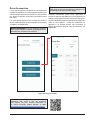 162
162
-
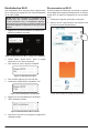 163
163
-
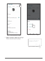 164
164
-
 165
165
-
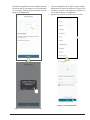 166
166
-
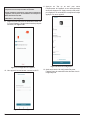 167
167
-
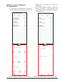 168
168
-
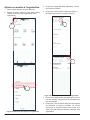 169
169
-
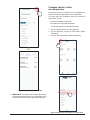 170
170
-
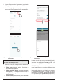 171
171
-
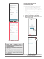 172
172
-
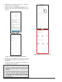 173
173
-
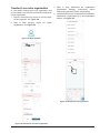 174
174
-
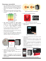 175
175
-
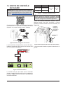 176
176
-
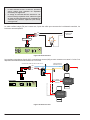 177
177
-
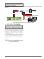 178
178
-
 179
179
-
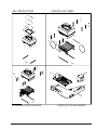 180
180
-
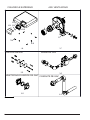 181
181
-
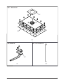 182
182
-
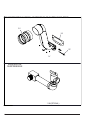 183
183
-
 184
184
-
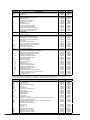 185
185
-
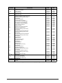 186
186
-
 187
187
-
 188
188


Rheem P-M404A-EN-N Manuel utilisateur
- Taper
- Manuel utilisateur
- Ce manuel convient également à
dans d''autres langues
- English: Rheem P-M404A-EN-N User manual