
4x8 SPACED 3" PICKET PANEL
ASSEMBLY INSTRUCTIONS
For use with: For use with:
4x8 Spaced Pickets 3.eps
(2) Rails
(13) Pickets
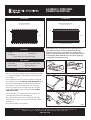
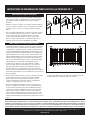
4x8 Spaced 3" Dogear Picket Panel
Actual size: 45"h x 91.875"w
4x8 Spaced Pickets 3.eps
(2) Rails
(13) Pickets
4x8 Spaced 3" Picket Panel
Actual size: 46"h x 91.875"w
3x8 Spaced Picket 1.5.eps
(2) Rails
(17) Pickets
3x8 Spaced 1.5" Picket Panel
Actual size: 33.5"h x 91.875"w
fig. 1
fig. 3 fig. 4
fig. 2
fig. 5
4x8 Spaced Pickets 3.eps
(2) Rails
(13) Pickets
4x8 Spaced 3" Dogear Picket Panel
Actual size: 45"h x 91.875"w
4x8 Spaced Pickets 3.eps
(2) Rails
(13) Pickets
4x8 Spaced 3" Picket Panel
Actual size: 46"h x 91.875"w
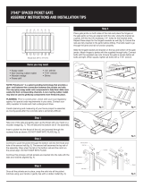
Note: PicketLock
™
is a patented technology that provides a
glue- and fastener-free connection between the pickets
and rails. You may spray soapy water onto components to
help them slide more easily into their corresponding channels.
A non-marring rubber mallet may also be used to gently tap
components more firmly into place.
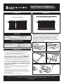
Assembling the panel
• 13 - pickets
• 2 - rails
Kit contents
• Soapy water
• Wooden wedge
• Non-marring rubber mallet
• Drill with square bit
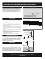
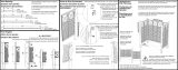
• Take one of the rails and gently open the throat with your hand
or a wooden wedge (fig. 1). This will become the bottom rail of
the assembly.
• Insert a picket into the throat of the rail, and proceed through
the routered hole as shown. DO NOT SNAP INTO PLACE (fig. 2).
• Continue to push the picket through the bottom rail into the
throat and hole of the second rail (fig. 3). The second rail
becomes the top rail of the assembly. Stop when the tab in
the bottom rail and the notch on the picket align. DO NOT
SNAP INTO PLACE.
• Continue this process until all pickets are inserted into the
rail with the tabs and notches aligned (fig. 4).
• Once all the pickets are in place, snap the rails into all the
picket notches using your hands or gently tap with a rubber
mallet (fig. 5).
• The panel assembly is now complete.
©2020 UFP Retail Solutions, LLC. All rights reserved. PicketLock is a trademark of UFP Industries, Inc.
68956 U.S. Hwy 131, White Pigeon, MI 49099 616.365.4201 11262_7/20
www.ufpi.com
Items needed
• 4 - mounting brackets
with fasteners*
*Some models do not include brackets

4x8 SPACED 3" PICKET PANEL INSTALLATION INSTRUCTIONS
©2020 UFP Retail Solutions, LLC. All rights reserved. PicketLock is a trademark of UFP Industries, Inc.
68956 U.S. Hwy 131, White Pigeon, MI 49099 616.365.4201 11262_7/20
www.ufpi.com
4x8 SPACED 3" PICKET PANEL INSTALLATION INSTRUCTIONS, CONTINUED
©2020 UFP Retail Solutions, LLC. All rights reserved. PicketLock is a trademark of UFP Industries, Inc.
68956 U.S. Hwy 131, White Pigeon, MI 49099 616.365.4201 11262_7/20
www.ufpi.com
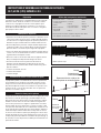
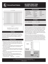
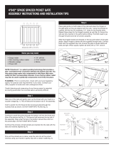
18" to 24"
6" of gravel
10" to 12"
Diameter
Level
Fig.4.pdf
fig. 3
96" from post-center
to post-center
Corner or End Post
Level
Fig.5.pdf
fig. 2
Digging postholes
Installing fences on sloped landscapes
Design and layout
Check local ordinances and regulations before building your
fence. Before construction, contact your local utility companies
to mark any underground cables and pipelines. In addition, it is
a good idea to discuss plans with any neighbors along your
proposed fence line.
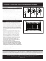
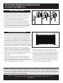
Most yards are relatively level and will allow for a fairly simple
installation. If your yard is steeply pitched or very uneven, be
sure to allow for the required mounting height of the adjacent
panel when setting your posts. You may need to "stair step"
the panels in extreme cases (fig. 1).
Post hole spacing is 96 in. post-center to post-center (fig. 2). Mark
post hole locations along string line. Double check all measure-
ments. Check local regulations for any special requirements for
post hole depth. The fence will be stronger if the end, corner and
gate posts are set at least 6" deeper than the line posts. Using a
posthole digger or power auger, dig the holes 10-12" wide and 6"
deeper than needed. Backfill the holes with 6" of gravel to drain
water away from the bottom of the posts (fig. 3). Keep the height
of your fence panels in mind when digging your postholes.
• Determine the number of posts, panels and gates needed to
complete the job based on the total linear footage. Take into
consideration post, panel and gate widths when determining
the total number of each.
• Adjust layout to accommodate as many full panels as possible.
If you must use a partial panel, place it in the farthest rear
corner of the property.
• Locate property boundaries and drive stakes into the ground
at corners and ends of fence line, based on local municipality
regulations.
• Stretch twine or heavy string between stakes and pull tight
to mark layout of fence line.
• Be sure to measure your fence panels and gates prior to
determining the location of the postholes. Place posts in the
following order along string line:
• End/corner posts • Gate posts • Line posts
Preparation Items you may need
• Fence posts*
• 4 PicketLock
Brackets per panel**
• Posthole digger
• Measuring tape
• Clear PVC cement
• Drill
• Screwdriver
• Level
• Chop saw
• String line
• Concrete
• Gravel
• Shims
• Pencil
• Safety glasses
• Gloves
* One per panel and one to complete fence run.
** Brackets are included with some models.
StepSpacedPic.ai
fig. 1
Step method
fig. 1
Step method

THE DIAGRAMS AND INSTRUCTIONS IN THIS BROCHURE ARE FOR ILLUSTRATION PURPOSES ONLY AND ARE NOT MEANT TO REPLACE A LICENSED PROFESSIONAL. ANY CONSTRUCTION OR
USE OF THE PRODUCT MUST BE IN ACCORDANCE WITH ALL LOCAL ZONING AND/OR BUILDING CODES. THE CONSUMER ASSUMES ALL RISKS AND LIABILITY ASSOCIATED WITH THE
CONSTRUCTION OR USE OF THIS PRODUCT. THE CONSUMER OR CONTRACTOR SHOULD TAKE ALL NECESSARY STEPS TO ENSURE THE SAFETY OF EVERYONE INVOLVED IN THE PROJECT,
INCLUDING, BUT NOT LIMITED TO, WEARING THE APPROPRIATE SAFETY EQUIPMENT. EXCEPT AS CONTAINED IN THE WRITTEN LIMITED WARRANTY, THE WARRANTOR DOES NOT
PROVIDE ANY OTHER WARRANTY, EITHER EXPRESS OR IMPLIED, AND SHALL NOT BE LIABLE FOR ANY DAMAGES, INCLUDING CONSEQUENTIAL DAMAGES.
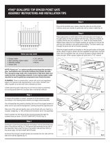
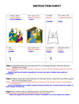
SpacedPicFig6.ai
fig. 6
2
"
Setting and installing posts and panels
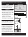
Installing brackets to posts
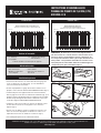
• Prepare the pre-assembled fence panels by sliding the
mounting brackets onto the rails with the open space at the
top. Slide the bracket fully onto the rail.
• While holding the bracket in place, attach one screw into one
of the slotted holes. Place the screw at the end of the slot
closest to the mounting face of the bracket (fig. 4).
• This will temporarily hold the bracket to the panel while you
place the complete panel between the posts. Do this for all
brackets on each fence panel prior to installation. You will be
able to slide the bracket outward to get a perfect fit if your
post opening is slightly wider than the suggested dimension.
• Starting at a corner, mix concrete in the first hole per the
instructions on the bag. Mix thoroughly and install the post into
the hole and tap the post to the proper depth. Measure to be
sure you can install the finished panel to the post with approxi-
mately a 2" gap from the ground to the bottom of the panel.
You may also need to leave a space from the highest point of
the panel to the top of the post (fig. 5). The spacing allows the
cap to be installed on top of the post without interference with
the top rail.
• Install the next post as described above, paying careful
attention to the spacing between posts. It is important to
determine the height requirement for mounting the next
panels, as you may need to leave more post above the
ground to accommodate its mounting height (especially
if you are installing the fence on an uneven landscape).
• Slide the panel between posts and position to the desired
height. Use wooden blocks or shims to obtain the proper
spacing from the ground. Using the supplied screws
(four per bracket), attach the panel to the posts. Be sure
to center the fence brackets on the post.
• Use a level to ensure the fence is plumb and the posts are
square with the ground. Brace the panel and post to hold the
position as the concrete sets (per the time frame established
in the manufacturer's instructions). Continue setting posts and
installing panels to complete the project. Once posts are set,
finish panel installation by using the provided screws to secure
the fence bracket to the panel.
• Install a post cap on each post using a clear PVC cement
or an exterior adhesive.
fig. 5
fig. 4
4x8 SPACED 3" PICKET PANEL INSTALLATION INSTRUCTIONS, CONTINUED
©2020 UFP Retail Solutions, LLC. All rights reserved. PicketLock is a trademark of UFP Industries, Inc.
68956 U.S. Hwy 131, White Pigeon, MI 49099 616.365.4201 11262_7/20
www.ufpi.com

fig. 1
fig. 3 fig. 4
fig. 2
fig. 5
Contenu de l'ensemble :
REMARQUE : PicketLock™ est une technologie brevetée
qui offre un lien sans colle ni attaches entre les lattes et les
longerons. Vous pouvez pulvériser de l’eau savonneuse sur
les composants afin de les aider à glisser plus facilement sur
leurs profilés correspondants. Un maillet en caoutchouc non
marquant peut aussi être utilisé afin de doucement frapper les
composants pour qu’ils soient bien en place.
4x8 Spaced Pickets 3.eps
Panneau de piquets de 7,62 cm (3 po)
espacés et à coins coupés en biais 4 x 8
Taille réelle : H de 114,3 cm (45 po) x L de 233,36 (91,875 po)
4x8 Spaced Pickets 3.eps
Panneau de piquets de 7,62 cm (3 po) espacés 4 x 8
Taille réelle : H de 116,84 cm (46 po) x L de 233,36 (91,875 po)
À utiliser avec :À utiliser avec :
Installation du panneau
Articles nécessaires
• Coins de bois
• Perceuse avec fleurette à
tête carrée
• Eau savonneuse
• Maillet en caoutchouc
non marquant
• Prenez l’une des traverses et ouvrez doucement la gorge à la
main, ou utilisez un coin de bois (fig. 1). Ceci deviendra la
traverse inférieure de l’ensemble.
• Insérez un piquet dans la gorge de la traverse et dans le trou
préparé, comme montré. NE PAS ENCLIQUER EN PLACE (fig. 2).
• Continuez de pousser le piquet à travers la traverse inférieure,
dans la gorge et le trou de la seconde traverse inférieure (fig. 3). La
deuxième traverse deviendra la traverse supérieure de l’ensemble.
Arrêtez lorsque la languette de la traverse inférieure et l’encoche
sur la latte s’alignent. NE PAS ENCLIQUER EN PLACE.
• Continuez ce processus jusqu’à ce que tous les piquets soient
insérés dans les traverses, les languettes et les encoches
alignées (fig. 4).
• Une fois tous les piquets en place, encliquez les traverses sur
toutes les encoches de piquets en utilisant vos mains ou en
tapant doucement avec un maillet en caoutchouc (fig. 5).
• L'assemblage du panneau est maintenant terminé.
INSTRUCTIONS D'ASSEMBLAGE DU
PANNEAU DE PIQUETS DE 7,62 CM (3 PO)
ESPACÉS 4 X 8
4x8 Spaced Pickets 3.eps
4x8 Spaced 3" Dogear Picket Panel
Actual size: 45"h x 91.875"w
4x8 Spaced Pickets 3.eps
4x8 Spaced 3" Picket Panel
Actual size: 46"h x 91.875"w
©2020 UFP Retail Solutions, LLC. Tous droits réservés. PicketLock est une marque de commerce de UFP Industries, Inc.
68956 U.S. Hwy 131, White Pigeon, MI 49099 616.365.4201 11262_7/20
www.ufpi.com
• 2 - traverses
• 13 - piquets
(2) traverses
(13)
piquets
(2) traverses
(13)
piquets
• 4 - supports de montage
avec fixations*
*Certains modèles n'incluent pas de supports

INSTRUCTIONS D'ASSEMBLAGE DU PANNEAU DE PIQUETS
DE 7,62 CM (3 PO) ESPACÉS 4 X 8
Consultez vos ordonnances et réglementations locales avant de
bâtir votre clôture. Avant de commencer à construire, veuillez
contacter vos compagnies locales de services publics pour
marquer tous câbles et pipelines souterrains. C'est aussi une
bonne idée de discuter des plans avec vos voisins le long de la
ligne proposée de la clôture.
La plupart des jardins sont relativement à niveau et permettront
une installation assez simple. Si votre jardin est incliné ou très
inégal, assurez-vous d'avoir la hauteur de montage nécessaire
du panneau adjacent lorsque vous installerez vos poteaux. Vous
aurez besoin de « créer un effet d'escalier avec vos panneaux
dans des cas extrêmes (fig. 1).
L'espacement des trous de poteaux est de 2,4 m (96 po) du centre
du poteau au centre du poteau (fig 2). Veuillez indiquer les em-
placements des trous de poteaux le long de la ligne du cordeau.
Vérifiez à nouveau toutes les mesures. Vérifiez les réglementa-
tions locales pour toutes les exigences particulières en matière
de profondeur des trous de poteaux. La clôture sera plus solide
si les poteaux d'extrémité, de coin et de barrière sont placés à au
moins 6 po de plus profonds que les poteaux de ligne. Utilisez la
tarière électrique ou bêche tarière de trou de poteau et creusez
les trous à 25,4 à 30,48 cm (10 à 12 po) de largeur et 15,24 cm (6
po) plus profonds que nécessaire. Remplissez les trous de 15,24
cm (6 po) de gravier pour drainer l'eau du bas des poteaux (fig. 3).
En creusant vos trous de poteaux, n'oubliez pas la hauteur de vos
panneaux de clôture.
• Déterminez le nombre de poteaux, panneaux et barrières néces-
saires pour terminer le projet selon le nombre de pieds linéaires
en tout. Prenez en compte la largeur des poteaux, panneaux et
barrières lorsque vous déterminez le nombre total de chacun.
• Ajustez la disposition pour tenir compte d'autant de panneaux
complets possibles. Si vous devez utiliser un panneau partiel,
placez-le dans le coin arrière le plus éloigné de la propriété.
• Trouvez les limites de la propriété et installez les piquets dans le
sol aux coins et aux extrémités de la clôture, conformément aux
réglementations municipales locales.
• Étirez une corde ou une ficelle lourde entre les piquets et tirez
bien pour marquer la disposition de la ligne de clôture.
• Assurez-vous de mesurer vos panneaux de clôture et
barrières avant de déterminer l'emplacement des trous de
poteaux. Placez les poteaux dans l'ordre suivant le long de la
ligne de cordeau :
• Poteaux d'extrémité / du coin
• Poteaux de la barrière
• Poteaux de ligne
Step 3Préparation
Installation de clôtures sur des terrains en pente
Creuser les trous pour les poteaux
Articles dont vous pourriez avoir besoin :
• Poteaux de clôture*
• 4 supports PicketLock
par panneau**
• Tarière
• Ruban à mesurer
• Ciment PVC
transparent
• Perceuse
• Tournevis
• Niveau
• Scie à tronçonner
• Ligne du cordeau
• Béton
• Gravier
• Cales
• Crayon
• Lunettes de
sécurité
• Gants
Conception et disposition
StepSpacedPic.ai
fig. 1
Step method
Méthode en plusieurs étapes
Diamètre de
25,4 à 30,48 cm
(10 à 12 po)
45,7 à 61 cm
(18 à 24 po)
gravier de 15,2 cm
(6 po) de profondeur
Niveau
Fig.4.pdf
fig. 3
fig. 1
Espacement de 2,4 m (96 po) du
centre du poteau au centre du poteau.
Poteau du coin
ou de l'extrémité
Niveau
Fig.5.pdf
fig. 2
*Un par panneau et un pour compléter la longueur de la clôture.
** Des supports sont inclus avec certains modèles.

INSTRUCTIONS D'ASSEMBLAGE DU PANNEAU DE PIQUETS
DE 7,62 CM (3 PO) ESPACÉS 4 X 8
©2020 UFP Retail Solutions, LLC. Tous droits réservés. PicketLock est une marque de commerce de UFP Industries, Inc.
68956 U.S. Hwy 131, White Pigeon, MI 49099 616.365.4201 11262_7/20
www.ufpi.com
LES DIAGRAMMES ET INSTRUCTIONS DE CETTE BROCHURE SONT À DES FINS D’ILLUSTRATION SEULEMENT ET NON PAS POUR REMPLACER UN PROFESSIONNEL AGRÉÉ. TOUTE
CONSTRUCTION OU UTILISATION DE CE PRODUIT DOIT ÊTRE CONFORME AUX RÈGLEMENTS DE ZONAGE ET/OU AUX CODES LOCAUX DU BÂTIMENT. LE CONSOMMATEUR ASSUME
TOUS LES RISQUES ET LES RESPONSABILITÉS EN LIEN AVEC LA CONSTRUCTION OU À L’UTILISATION DE CE PRODUIT. LE CLIENT OU L’ENTREPRENEUR DOIT PRENDRE TOUTES
LES MESURES NÉCESSAIRES À ASSURER LA SÉCURITÉ DE TOUTE PERSONNE IMPLIQUÉE DANS LE PROJET, INCLUANT, MAIS SANS S’Y LIMITER, AU PORT D’UN ÉQUIPEMENT DE
SÉCURITÉ APPROPRIÉ. SAUF INDICATION DANS LA GARANTIE LIMITÉE ÉCRITE, LE GARANT NE FOURNIT AUCUNE AUTRE GARANTIE, FORMELLE OU TACITE, ET NE SERA PAS TENU
RESPONSABLE DE TOUS DOMMAGES, INCLUANT LES DOMMAGES INDIRECTS.
SpacedPicFig6.ai
fig. 6
2
"
fig. 5
5,08 cm (2 po)
• Préparez les panneaux de la barrière préinstallés en glissant les
supports de fixation sur les traverses en gardant l'espace ouvert
au dessus. Glissez le support complètement sur la traverse.
• En maintenant le support en place, fixez une vis dans l'un des
trous oblongs. Placez la vis à l'extrémité de la fente la plus
proche de la façade de fixation du support (fig. 4).
• Ceci fixera temporairement le support au panneau pendant que
vous placez le panneau complet entre les poteaux. Faites de
même pour tous les supports sur chaque panneau de la barrière
avant l'installation. Vous pourrez glisser le support vers l'extérieur
pour obtenir un parfait ajustement si l'ouverture de votre poteau
est légèrement plus large que la dimension suggérée.
Installer les supports aux poteaux
• En commençant par un coin, mélangez le béton dans le premier
trou en suivant les instructions qui se trouvent sur le sac. Mélangez
à fond et installez le poteau dans le trou et appuyez sur le poteau
pour l'enfoncer à la profondeur qui convient. Mesurez pour vous
assurer de pouvoir installer le panneau terminé au poteau avec un
espace d’environ 5 cm (2 po) entre le sol et le bas du panneau. Vous
aurez également peut-être besoin de laisser un peu d'espace entre
le point le plus élevé du panneau et la partie supérieure du poteau
(fig. 5). L'espace permet d'installer le plafond sur la partie supérieure
du poteau sans qu'il y ait d'interférence avec la traverse supérieure.
• Installez le poteau suivant tel que décrit ci-dessus, en faisant
attention à l'espace entre les poteaux. Il est important de détermine
l'exigence en matière de hauteur pour assembler les panneaux
suivants, car vous aurez possiblement besoin de laisser plus de
poteaux au-dessus du sol pour vous adapter à sa hauteur d'assem-
blage (en particulier si vous installez la barrière sur un
terrain inégal).
• Glissez le panneau entre les poteaux et placez-le à la hauteur
souhaitée. Utilisez des morceaux ou cales de bois pour obtenir
l'espacement adéquat par rapport au sol. En utilisant les vis fournies
(quatre par support), fixez le panneau aux poteaux. Assurez-vous de
centrez les supports de la barrière sur le poteau.
• Utilisez un niveau pour vous assurer que la barrière est à la
verticale et que les poteaux sont à l'équerre avec le sol. Ren-
forcez le panneau et le poteau pour maintenir la position pendant
que le béton s'installe (selon la durée de temps stipulée dans les
instructions du manufacturier). Continuez à placer les poteaux
et installer les panneaux pour terminer votre projet. Une fois les
poteaux placés, terminez l'installation des panneaux en utilisant
les vis fournies pour fixer le support de la barrière au panneau.
• Installez un capuchon de poteau sur chaque poteau en utilisant
un ciment à PVC ou un adhésif pour l’extérieur.
Placer et installer les poteaux et panneaux
fig. 4

Para usar con: Para usar con:
4x8 Spaced Pickets 3.eps
(2) pretiles
(13) estacas
Panel de estacas 4x8 con esquinas recortadas (Dog Ear) y espaciado de 7.6 cm
Tamaño real: 1.17 m AL x 2.33 m AN
4x8 Spaced Pickets 3.eps
(2) pretiles
(13) estacas
Panel de estacas 4x8 con esquinas recortadas (Dog Ear) y espaciado de 7.6 cm
Tamaño real: 1.17 m AL x 2.33 m AN
4x8 Spaced Pickets 3.eps
(2) pretiles
(13) estacas
Panel de estacas 4x8 con espaciado de 7.6 cm
Tamaño real: 1.17 m AL x 2.33 m AN
4x8 Spaced Pickets 3.eps
(2) pretiles
(13) estacas
Panel de estacas 4x8 con espaciado de 7.6 cm
Tamaño real: 1.17 m AL x 2.33 m AN
fig. 1
fig. 3 fig. 4
fig. 2
fig. 5
NOTA: PicketLock™ es una tecnología patentada que proporciona
una conexión libre de pegamentos y herrajes entre las estacas y
el pretil. Usted puede rociar agua jabonosa en los componentes
para ayudarles a deslizarse más fácilmente en sus canales
correspondientes. También puede usarse un mazo de hule que
no daña superficies para golpear levemente los componentes en
forma más firme en su lugar.
Un kit incluye
• 2 - pretiles
• 13 - estacas
Artículos que se necesitan
Ensamble del panel
• Tome uno de los pretiles y abra cuidadosamente la estricción
con la mano o una cuña de madera (fig. 1). Esta pieza se
convertirá en el pretil inferior del ensamblado.
• Inserte la primera estaca en la estricción del pretil y prosiga a
través del orificio recortado, como se muestra. NO DESLICE
PRESIONANDO PARA QUE QUEDE EN SU LUGAR (fig. 2).
• Continúe empujando la estaca a través del pretil inferior en la
estricción y orificio del segundo pretil (fig. 3). El segundo pretil
se convierte en el pretil superior del ensamblado. Deténgase
cuando la pestaña en el pretil inferior y la muesca de la estaca
lleguen a alinearse. NO DESLICE PRESIONANDO PARA QUE
QUEDE EN SU LUGAR.
• Continúe este proceso hasta que todas las estacas queden
insertadas en los pretiles, con las pestañas y las muescas
alineadas (fig. 4).
• Una vez que todas las estacas estén en su lugar, deslice
empujando todas las pestañas del pretil en todas las muescas
de las estacas usando sus manos o golpee suavemente con un
mazo de hule (fig. 5).
• El ensamblado del panel ya está completo.
INSTRUCCIONES DE ENSAMBLADO DE
PANEL DE ESTACA 4x8 ESPACIADO DE 3"
©2020 UFP Retail Solutions, LLC. Todos los derechos reservados. PicketLock es una marca comercial de UFP Industries, Inc.
68956 U.S. Hwy 131, White Pigeon, MI 49099 616.365.4201 11262_7/20
www.ufpi.com
• Agua jabonosa
• Cuña de madera
• Mazo de hule que no
daña superficies
• Taladra con una broca
cuadrada
• 4 - soportes de montaje
con tornillos*
*Algunos modelos no incluyen soportes

fig. 3
El espaciamiento entre los agujeros de los postes es de 96 pulg.
(244 cm) de centro a centro (fig. 2). Marque las ubicaciones
de los agujeros para los postes a lo largo de la línea marcada
por el cordón. Revise dos veces todas las medidas. Verifique
si las regulaciones locales marcan algún requisito especial
para la profundidad de los postes. La cerca será más fuerte
si la profundidad de los postes de los extremos, las esquinas
y la puerta es 15.2 cm mayor que la de los otros postes. Con
un cavador de hoyos de poste o una barrena eléctrica, cava
hoyos de 25.4 cm a 30.5 cm de diámetro, con 15.2 cm más de la
profundidad necesaria. Rellena el fondo de los hoyos con 15.2
cm de grava para drenar el agua de la parte inferior de los postes
(fig. 3). Ten en cuenta la altura de los paneles de la cerca cuando
caves los hoyos de los postes.
Preparación
Artículos que se necesitan
StepSpacedPic.ai
fig. 1
Step method
Método de escalonamiento
fig. 1
18 a 24
pulgadas
10 a 12
pulgadas de
diámetro.
Nivel
Fig.4.pdf
6 pulg.
de grava
Cómo cavar huecos para los postes
Instalación de cercas en jardines inclinados
Diseño y distribución
Compruebe ordenanzas y normas locales antes de construir su
cerca. Antes de la construcción, póngase en contacto con las
empresas locales de servicios públicos para marcar los cables
subterráneos y tuberías. Además, es una buena idea hablar
sobre estos planes con los vecinos a lo largo de su línea de
cerca propuesta.
• Determine el número de postes, paneles y puertas necesarias
para completar el trabajo en base al total de los metros lineales.
Tome en consideración los anchos de los postes, paneles y
puertas cundo determine el número total de cada uno de ellos.
• Modifique el diseño para dar cabida a tantos paneles completos
como sea posible. Si debe usar parte de un panel, colóquelo en
la esquina posterior más alejada de la propiedad
• Ubique los límites de la propiedad y meta las estacas en el
suelo en las esquinas y extremos de línea de la cerca, siguiendo
los reglamentos de la municipalidad local.
• Estire el hilo o el cordel pesado entre las estacas y tire con
fuerza para marcar el diseño de la línea de la cerca.
• Asegúrese de medir los paneles de la cerca y las puertas antes de
determinar la ubicación de los huecos para los postes. Coloque
los postes en el siguiente orden a lo largo de la línea del cordel:
• Postes del extremo/esquina • Postes de la puerta • Postes de línea
La mayoría de los jardines son relativamente planos y permiten
una instalación sencilla. Si su jardín es muy empinado o desigual,
asegúrese de dejar la altura de montaje deseado para el panel
adyacente cuando coloque los postes. En casos extremos es
posible que necesite "escalonar" los paneles (fig. 1).
*Uno por panel y uno para completar el cerco.
** Los soportes se incluyen con algunos modelos.
• Postes de cerca*
• 4 soportes PicketLock
por panel**
• Cavador de hoyos
de poste
• Cinta de medir
• Cemento PVC
transparente
• Taladro
• Destornillador
• Nivel
• Sierra caladora
• Cuerda
alineadora
• Concreto
• Grava
• Cuñas
• Lápiz
• Gafas de
seguridad
• Guantes
96 pulg. entre postes,
de centro a centro
Poste de la esquina
o del extremo
Nivel
Fig.5.pdf
fig. 2
INSTRUCCIONES DE ENSAMBLADO DE PANEL DE ESTACA 4x8 ESPACIADO DE 3"
©2020 UFP Retail Solutions, LLC. Todos los derechos reservados. PicketLock es una marca comercial de UFP Industries, Inc.
68956 U.S. Hwy 131, White Pigeon, MI 49099 616.365.4201 11262_7/20
www.ufpi.com

INSTRUCCIONES DE ENSAMBLADO DE PANEL DE ESTACA 4x8 ESPACIADO DE 3"
©2020 UFP Retail Solutions, LLC. Todos los derechos reservados. PicketLock es una marca comercial de UFP Industries, Inc.
68956 U.S. Hwy 131, White Pigeon, MI 49099 616.365.4201 11262_7/20
www.ufpi.com
LOS DIAGRAMAS E INSTRUCCIONES EN ESTE FOLLETO SÓLO TIENEN FINES ILUSTRATIVOS Y NO PRETENDEN SUSTITUIR A UN PROFESIONAL CON LICENCIA. CUALQUIER CONSTRUCCIÓN O USO DEL
PRODUCTO DEBE ESTAR EN CONFORMIDAD CON TODOS LOS CÓDIGOS DE CONSTRUCCIÓN Y/O URBANISMO LOCALES. EL CONSUMIDOR ASUME TODA LA RESPONSABILIDAD, ASÍ COMO LOS RIESGOS
RELACIONADOS CON LA CONSTRUCCIÓN O EL USO DE ESTE PRODUCTO. EL CONSUMIDOR O EL CONTRATISTA DEBEN TOMAR TODAS LAS MEDIDAS NECESARIAS PARA GARANTIZAR LA SEGURIDAD DE
TODAS LAS PERSONAS QUE PARTICIPAN EN EL PROYECTO, INCLUYENDO, ENTRE OTROS, EL USO DE LOS EQUIPOS DE SEGURIDAD ADECUADOS. SALVO EN LOS CASOS QUE FIGURAN EN EL ESCRITO DE
GARANTÍA LIMITADA, EL GARANTE NO OFRECE NINGUNA OTRA GARANTÍA, EXPRESA O IMPLÍCITA, NI SE CONSIDERARÁ RESPONSABLE DE CUALQUIER DAÑO, INCLUYENDO LOS DAÑOS CONSIGUIENTES.
fig. 4
Cómo configurar e instalar los postes y paneles
Cómo instalar los soportes a los postes
• Prepara los paneles de cerca preensamblados deslizando los
soportes de montaje en las barandas con el espacio abierto
hacia arriba. Desliza completamente el soporte sobre la
baranda.
• Mientras sostienes el soporte en su lugar, instala un tornillo en
uno de los orificios ranurados. Coloca el tornillo en el extremo
de la ranura más cercano a la cara de montaje del soporte
(fig. 4).
• Esto sostendrá temporalmente el soporte en el panel mientras
colocas el panel completo entre los postes. Haz esto mismo
con los cuatro soportes en cada panel de la cerca antes
de la instalación. Podrás deslizar el soporte hacia afuera
para conseguir el ajuste perfecto si tu abertura de poste es
ligeramente más ancha que la medida recomendada.
• Comenzando desde la esquina, mezcla el concreto en el primer
orificio de acuerdo con las instrucciones de la bolsa. Mezcla
completamente, instala el poste en el orificio y golpea el poste
hasta la profundidad adecuada. Mide bien para asegurar que
puedas instalar el panel terminado al poste con un espacio de
aproximadamente 5.1 cm entre el suelo y la parte inferior del
panel. También pudiera ser necesario dejar un espacio desde
el punto más alto del panel hasta la parte superior del poste
(fig. 5). El espaciado permite que el tope se instale en la parte
superior del poste sin interferir con la baranda superior.
• Instala el poste siguiente como se describió más arriba y
presta especial atención al espaciado entre los postes. Es
importante determinar la altura requerida para montar los
paneles siguientes, ya que pudiera ser necesario dejar más
poste por encima del nivel de la tierra para ajustarse a su altura
de montaje (especialmente si estás instalando la cerca sobre un
terreno irregular).
• Desliza el panel entre los postes y colócalo a la altura deseada.
Usa bloques de madera o cuñas para lograr el espaciado
preciso desde el suelo. Fija el panel a los postes con los
tornillos suministrados (cuatro por soporte). Asegúrate de
centrar los soportes de la cerca en el poste.
• Usa un nivel para garantizar que la cerca esté a plomo y los
postes a escuadra con respecto al suelo. Asegura el panel y
los postes para mantener la posición a medida que fragua el
concreto (en el tiempo establecido por las instrucciones del
fabricante). Continua colocando los postes e instalando los
paneles hasta completar el proyecto. Una vez que los postes
estén colocados, termina la instalación de los paneles con los
tornillos proporcionados para asegurar el soporte de la cerca al
panel.
• Coloque una tapa de poste en cada poste utilizando cemento
PVC transparente o un adhesivo para uso exterior.
SpacedPicFig6.ai
fig. 6
2
"
5,08 cm (2 po)
fig. 5
-
 1
1
-
 2
2
-
 3
3
-
 4
4
-
 5
5
-
 6
6
-
 7
7
-
 8
8
-
 9
9


Outdoor Essentials 128004 Mode d'emploi
- Taper
- Mode d'emploi
dans d''autres langues
Documents connexes


Autres documents
-
 Yardistry YP21013 Mode d'emploi
-
 Veranda 141568 Mode d'emploi
-
 Veranda 181983 Guide d'installation
-
 Veranda 181980 Guide d'installation
-
 Veranda 181981 Guide d'installation
-
Classic QS2-0W Manuel utilisateur
-
Vita VT17631 Mode d'emploi
-
 Yardistry YP21017 Guide d'installation
-
 Candy Cane Lane 66825_THD-MP1 Guide d'installation
-
STIEBEL ELTRON Beilage Temperaturbegrenzug UFP 5 t Operation Instruction


