arietta ALZ430SSA Guide d'installation
- Catégorie
- Hottes
- Taper
- Guide d'installation
Ce manuel convient également à

Installation Instructions Guide
Guía de Instrucciones para Instalación
Guide d’instructions d’installation
READ AND SAVE THESE INSTRUCTIONS
LEA Y GUARDE ESTAS INSTRUCCIONES
LIRE ET CONSERVER CES INSTRUCTIONS
LIB0121601
English page 2
Español página 13
Français page 23

2
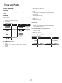
Table of Contents
Important Safety Instructions............................................... 2
Tools and Parts.......................................................................3
Product Dimensions.............................................................. 4
Electrical Requirements........................................................ 4
Venting Requirements........................................................... 5
Venting Methods.................................................................... 5
Installation Instructions......................................................... 6
Electrical Connection............................................................ 8
Hood Description................................................................... 9
Range Hood Care...................................................................10
Warranty.................................................................................. 12
APPROVED FOR RESIDENTIAL APPLIANCES
FOR RESIDENTIAL USE ONLY
READ AND SAVE THESE INSTRUCTIONS
PLEASE READ ENTIRE INSTRUCTIONS BEFORE PROCEEDING.
INSTALLATION MUST COMPLY WITH ALL LOCAL CODES.
IMPORTANT: Save these Instructions for the Local Electrical
Inspector’s use.
INSTALLER: Please leave these Instructions with this unit for
the owner.
OWNER: Please retain these instructions for future
reference.
Safety Warning:Turn off power circuit at service panel and lock
out panel before wiring this appliance.
Requirement 120 VAC, 60 Hz. 15 or 20 A Branch Circuit
IMPORTANT SAFETY INSTRUCTIONS
WARNING: TO REDUCE THE RISK OF FIRE, ELECTRIC
SHOCK, OR INJURY TO PERSONS, OBSERVE THE
FOLLOWING:
■ Use this unit only in the manner intended by the
manufacturer. If you have questions, contact the
manufacturer.
■ Before servicing or cleaning the unit, switch power off at
service panel and lock the service disconnecting means to
prevent power from being switched on accidentally. When
the service disconnecting means cannot be locked, securely
fasten a prominent warning device, such as a tag to the
service panel.
■ Installation work and electrical wiring must be done by
qualied person(s) in accordance with all applicable codes
and standards, including re-rated construction.
■ Sufcient air is needed for proper combustion and
exhausting of gases through the ue (chimney) of fuel
burning equipment to prevent backdrafting. Follow the
heating equipment manufacturer’s guideline and safety
standards such as those published by the National Fire
Protection Association (NFPA), the American Society for
Heating, Refrigeration and Air Conditioning Engineers
(ASHRAE), and the local code authorities.
■ When cutting or drilling into wall or ceiling; do not damage
electrical wiring and other hidden utilities.
■ Ducted fans must always be vented outdoors.
CAUTION: For general ventilating use only. Do not use to
exhaust hazardous or explosive materials and vapors.
CAUTION: To reduce risk of re and to properly exhaust air,
be sure to duct air outside - do not vent exhaust air into
spaces within walls or ceilings, attics or into crawl spaces, or
garages.
WARNING: TO REDUCE THE RISK OF FIRE, USE ONLY METAL
DUCTWORK
WARNING: TO REDUCE THE RISK OF A RANGE TOP
GREASE FIRE:
■ Never leave surface units unattended at high settings.
Boilovers cause smoking and greasy spillovers that may
ignite. Heat oils slowly on low or medium settings.
■ Always turn hood ON when cooking at high heat or when
ambeing food (i.e. Crepes Suzette, Cherries Jubilee,
Peppercorn Beef Flambé).
■ Clean ventilating fans frequently. Grease should not be
allowed to accumulate on fan or lter.
■ Use proper pan size. Always use cookware appropriate for
the size of the surface element.
WARNING: TO REDUCE THE RISK OF INJURY TO
PERSONS IN THE EVENT OF A RANGE TOP GREASE FIRE,
OBSERVE THE FOLLOWING:
a
■ SMOTHER FLAMES with a close tting lid, cookie sheet, or
metal tray, then turn off the burner. BE CAREFUL TO
PREVENT BURNS. If the ames do not go out
immediately, EVACUATE AND CALL THE FIRE
DEPARTMENT.
■ NEVER PICK UP A FLAMING PAN - you may get burned.
■ DO NOT USE WATER, including wet dishcloths or towels -
a violent steam explosion will result.
■ Use an extinguisher ONLY if:
-You know you have a class ABC extinguisher, and you
already know how to operate it.
– The re is small and contained in the area where it
started.
– The re department is being called.
– You can ght the re with your back to an exit.
a
Based on “Kitchen Fire Safety Tips” published by NFPA.
WARNING: To reduce the risk of re or electrical shock,
do not use this fan with any solid-state speed control device.
READ AND SAVE THESE INSTRUCTIONS

3
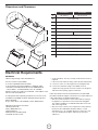
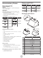
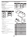
Parts supplied
Removing the packaging
CAUTION!
Remove carton carefully, wear gloves to protect against sharp
edges.
WARNING!
Remove the protective lm covering the product before putting
into operation.
• Hood assembly with blower and LED lamps already installed.
• 6” (15.2 cm) round air transition
• Grease lters
• Hardware bag with:
Part Qty Part Qty
5x45 mm
4
Torx 20 adapter
1
4.5x13 mm
4
10 x 60 mm wall
anchors
4
3.5x9.5 mm
2
5.4x75 mm screws
(for 10x60 mm wall
anchors)
4
Torx 10 adapter
1
Tools/Materials required
• Level
• Drill with 1¼” (3.2 cm),
1
⁄8” (3.2 mm), and
1
⁄16” (4,8 mm)
drill bits
• Pencil
Tools and Parts
• Wire stripper or utility knife
• Tape measure or ruler
• Pliers
• Caulking gun and weatherproof caulking compound
• Vent clamps
• Jigsaw or keyhole saw
• Flat-blade screwdriver
• Metal snips
• Phillips screwdrive
r
Parts needed
• Home power supply cable
• ½” (12.7 mm) UL listed or CSA approved strain relief
• 3 UL listed wire connectors
For vented installations, you will also need:
• 1 wall or roof cap
• Metal vent system
Parts not supplied
Optional Accessories
Kit # Part Kit # Part
No Return
Valve
KIT0102873 Recirculating 30” KIT01939
36” KIT01940
Duct Cover
6” height
30” KIT01941
36” KIT01942
Duct Cover
12” height
30” KIT01944
36” KIT01945
CFM
Reduction
KIT02748 Grease
Filter
KIT01668

4
Dimensions and Clearances
F
M
D
C
B
A
E
H
G
I
Recirculating
Kit height
J
Duct cover
Kit height
K (6”)
L (12”)
ALZ430SSA ALZ436SSA
A 30” (76 cm) 36” (91.54 cm)
B 23
7
⁄64” (58.7 cm)
C 17
63
⁄64” (45.7 cm)
D 12
3
⁄64” (30.6 cm)
E 2
10
⁄32” (5.9 cm)
F 29
4
⁄32” (74 cm) 35
7
⁄32”(89.5 cm)
G 7
3
⁄32” (18 cm)
H 2
9
⁄16” (6.5 cm)
I
13
⁄32” (1 cm)
J 21
59
⁄64 (55.7 cm)
K 23
15
⁄16 (60.8 cm)
L 29
59
⁄64 (76 cm)
M 6" (15.24 cm)
Electrical Requirements
IMPORTANT
Observe all governing codes and ordinances.
It is the customer’s responsibility:
To contact a qualied electrical installer.
To assure that the electrical installation is adequate and in
conformance with National Electrical Code, ANSI/NFPA 70
— latest edition*, or CSA Standards C22.1-94, Canadian
Electrical Code, Part 1 and C22.2 No.0-M91 - latest edition** and
all local codes and ordinances.
If codes permit and a separate ground wire is used, it is recom-
mended that a qualied electrician determine that the ground
path is adequate.
A copy of the above code standards can be obtained from:
National Fire Protection Association
1 Batterymarch Park
Quincy, MA 02169-7471
CSA International
8501 East Pleasant Valley Road
Cleveland, OH 44131-5575
• A 120 volt, 60 Hz., AC only, 15-amp, fused electrical circuit is
required.
• If the house has aluminum wiring, follow the procedure below:
1. Connect a section of solid copper wire to the pigtail leads.
2. Connect the aluminum wiring to the added section of
copper wire using special connectors and/or tools designed
and UL listed for joining copper to aluminum.
Follow the electrical connector manufacturer’s recommended
procedure. Aluminum/copper connection must conform with local
codes and industry accepted wiring practices.
• Wire sizes and connections must conform with the rating of
the appliance as specied on the model/serial rating plate.
The model/serial plate is located behind the lter on the rear
wall of the range hood.
• Wire sizes must conform to the requirements of the National
Electrical Code, ANSI/NFPA 70 (latest edition), or CSA
Standards C22. 1-94, Canadian Electrical Code, Part 1 and
C22.2 No. 0-M91 (latest edition and all local codes and
ordinances.

5
Preparation
Do not cut a joist or stud unless absolutely necessary. If a joist or
stud must be cut, then a supporting frame must be constructed.
Fittings material is provided to secure the hood to most types of
walls/ceilings.
However, a qualied technician must verify suitability of the mate-
rials in accordance with the type of wall/ceiling.
Before making cutouts, make sure there is proper clearance with-
in the ceiling or wall for exhaust vent.
Hood installation height above cooktop is the users preference.
The lower the hood is above the cooktop, the more efcient the
capturing of cooking odors, grease and smoke.
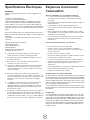
CAUTION: Mount this hood so that the bottom edge above the
cooking surface is at 30” (76.2 cm) minimum if a gas range is
used or from 24” (61 cm) to 30” (76.2 cm) if an electric range is
used. Household use, please, read installation manual for specic
application. Check your ceiling height and the hood height maxi-
mum before you select your hood.
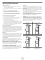
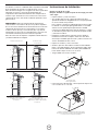
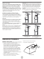
Venting through the roof Non Vented (recirculating)
A
B
C
F
F
C
E
Venting through the wall
F
A
B
D
F
C
A
B
A. 6” round transition
B. 6” round duct system
C. Cabinet / Duct cover kit
D. 90° elbow
E. Recirculating kit
F. Installation height:
Gas range MIN: 30” (76.2 cm)
Electric range: from 24” (61 cm ) to 30”
(76.2 cm)
Venting Requirements
(Ducted models only)
• Vent system must terminate to the outdoors, except for non
vented (recirculating) installations.
• Do not terminate the vent system in an attic or other enclosed
area.
• Do not use 4” (10.2 cm) laundry-type wall cap.
• Use metal vent only. Rigid metal vent is recommended.
Plastic or metal foil vent is not recommended.
• The length of vent system and number of elbows should
be kept to a minimum to provide efcient performance.
For the most efcient and quiet operation:
• Use no more than three 90° elbows.
• Make sure there is a minimum of 24” (61 cm) of straight vent
between the elbows if more than 1 elbow is used.
• Do not install 2 elbows together.
• Use clamps to seal all joints in the vent system.
• The vent system must have a damper. If the roof or wall cap has
a damper, do not use the damper supplied with the range hood.
• Use caulking to seal exterior wall or roof opening around the cap.
• The size of the vent should be uniform.
Cold weather installations
An additional back draft damper should be installed to minimize
backward cold air ow and a thermal break should be installed to
minimize conduction of outside temperatures as part of the vent
system. The damper should be on the cold air side of the thermal break.
The break should be as close as possible to where the vent
system enters the heated portion of the house.
Makeup air
Local building codes may require the use of makeup air systems
when using ventilation systems with greater than specied CFM
of air movement. The specied CFM varies from locale to locale.
Consult your HVAC professional for specic requirements in your area.
Venting Methods
This hood is factory set for venting through the roof (vertical
discharge) or wall (horizontal discharge). A 6” (15.24 mm) round
duct system is needed for installation (not included).
NOTE: Flexible vent is not recommended. Flexible vent creates
back pressure and air turbulence that greatly reduce perfor-
mance. Vent system can terminate either through the roof or wall.
To vent through a wall, a 90° elbow is needed.
For Non-Vented (recirculating) Installations
If it is not possible to vent cooking fumes and vapors to the out-
side, the hood can be used in the non-vented (recirculating) ver-
sion, using the recirculating kit . Fumes and vapors are recycled
through the round grid. See optional accesories section.

6
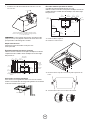
Mark holes
Select the vent option that your installation will require and proceed to
that section:
Outside top exhaust
Use the diagram or the hood as a template and mark the locations on
the cabinet for ductwork, electrical wiring and keyhole screw slots.
35
⁄64”
(1.4 cm)
Wiring access knockout
(cabinet bottom side)
Mounting
screws (4)
6
17
⁄64”
(15.9 cm)
Vent
shims
CENTER
LINE
Cabinet
front side
7
3
⁄32”
(18 cm)
2
19
⁄32”
(6.6 cm)
13
⁄32”
(1 cm)
1
11
⁄16”
(4.3 cm)
10
37
⁄64”
(26.86 cm)
Ø
55
⁄64”
(2.2cm)
1
47
⁄64”
(4.4 cm)
Cabinet bottom side
4
7
⁄32”
(10.7cm)
4
7
⁄32”
(10.7cm)
Vent
system hole
For recessed bottom cabinet only
If the cabinets have front, side or back trim, make 2 wood shims the
width of the trim and attach them to the cabinet bottom recess on
both sides.
Wood shims
Outside rear exhaust
(Horizontal duct Ø 6” (15.2 cm))
Use the diagram or the hood as a template and mark the locations on
the wall for ductwork, electrical wiring and keyhole screw slots.
4
7
⁄32”
(10.7cm)
1
27
⁄64”
(3.6cm)
4
27
⁄32”
(12.3cm)
4
61
⁄64”
(12.6cm)
9
⁄32”
(0.7cm)
4
7
⁄32”
(10.7cm)
6
17
⁄64”
(15.9cm)
3
25
⁄32”
(9.6cm)
6
57
⁄64”
(17.5cm)
6
57
⁄64”
(17.5cm)
1
11
⁄16”
(4.3cm)
1
1
⁄16”
(2.7cm)
55
⁄64”
(2.2cm)
1
37
⁄64” (4 cm)
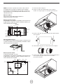
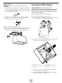
Installation instructions
Ducting version
After having chosen the vent option, proceed as follows:
• Prepare duct and conduit cut outs as needed.
• If possible, disconnect and move freestanding or slide-in
range from cabinet opening to provide easier access to rear
wall.
Otherwise put a thick, protective covering over countertop,
cooktop or range to protect from damage and debris. Select
a at surface for assembling the unit. Cover that surface with
a protective covering and place all canopy hood parts and
hardware in it.
• Determine and mark the centerline on the wall where the
canopy hood will be installed. Select a mounting height co-
fortable for the user and mark on wall.
• Prepare duct and conduit cut outs as needed.
• Remove the duct knockouts using a at blade screwdriver
and a small hammer.
• Use the screwdriver by knocking out the pannel in similar
fashion to a scalpel.
• Take care of sharp edges.
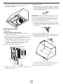
A
B
A. Vertical discharge
B. Horizontal discharge
• Attach the 6” round air transition over knockout opening with
2 - 3.5 x 9.5 mm screws.
A
C
C
B
A. 6” round air transition (vertical discharge installation)
B. 6” round air transition (horizontal discharge installation)
C. 2 - 3.5 x 9.5 mm installation screws
NOTE: The exhaust adaptor/damper can be installed up to 1
inch on either side of the hood center to accommodate offcenter
ductwork. In extreme offcenter installations, one end of the duct
connector may need to be trimmed to clear the electrical cable
clamp.

7
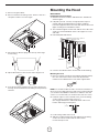
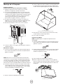
Mounting the Hood
Wall Installation
Install framing for hood support
1. Mark the screw hole locations indicated in the “Outside rear
exhaust” gure.
2. If drywall is present, cut away enough drywall to expose 2
vertical studs at the indicated holes location. Install two
horizontal supports between two wall studs at the bottom and
upper mounting holes installation location.
3. The horizontal support must be ush with the room side of the
studs. Use cleats behind both sides of the support to secure
wall studs.
4. Reinstall drywall and renish.
View from rear
Mounting
Support
Centerline of
Installation
Space
IMPORTANT: Framing must be capable of
supporting 100 lbs.
Cleats
5. Cut holes at marked locations for duct and electrical wiring.
Mounting the hood
1. Drive a mounting screw (from the hardware package) partway
into each center of the narrow neck of the keyhole slots
marked on the cabinet bottom or the wall’s support frame.
NOTE: You should consider the wall’s construction material in or-
der to choose the right wall anchor and screw. For plywood walls
you should use the 10x60 mm wall anchors and the 5.4x75 mm
screws. For concrete walls you should use the 5x45 mm screws.
2. Install the 2 pieces of the selected screws on the mountings
screws location (see the image). Leave a
1
⁄4”
(6.4 mm) gap between the wall and the back of the screw
head to slide range hood into place.
1
⁄4”
(6.4 mm)
3. Fix the wiring conduit of the hood.
4. Slide the hood back against the wall. Tighten the mounting
screws. Be sure the screw heads are in the narrow
neck of the keyhole slot.
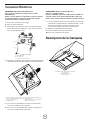
1. Remove the grease lters.
2. Remove the blower mounting screws. Put the screws in a
safe place in order to use them again.
3. Set free the two blower springs from the top of the range
hood housing.
4. Flip the blower base to the rear face of the range hood.
5. Insert the two blower springs to the top of the range hood
housing, Secure it with the four mounting screws previously
released.

8
A
B
A. Mounting Screws
B. Lower security screws (Wall Installation)
5. Drive 2 pieces of the selected screws in the lower security
screws location (see the image above).
6. Connect Ductwork to hood.
Cabinet Installation
NOTE: Your cabinet must be able to support at least
88 lb (40 kg).
7. Drive a mounting screw (from the hardware package) partway
into each center of the narrow neck of the keyhole slots
marked on the cabinet bottom or the wall’s support frame.
8. Install the 4 - 4 x 8 mm mounting screws. Leave a
1
⁄4”
(6.4 mm) gap between the wall and the back of the screw
head to slide range hood into place.
1
⁄4”
(6.4 mm)
9. Fix the wiring conduit of the hood.
10. Slide the hood back against the cabinet. Tighten the
mounting screws. Be sure the screw heads are in the narrow
neck of the keyhole slot.
A
A. Mounting Screws
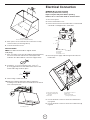
Electrical Connection
WARNING: Electrical Shock Hazard
Disconnect power before servicing.
Replace all parts and panels before operating.
Failure to do so can result in death or electrical shock.
1. Disconnect power.
2. Remove terminal box cover.
3. Remove the knockout in the terminal box cover and install
a UL listed or CSA approved
1
⁄2” strain relief.
C
B
A
A. Terminal box
B. Knockout
C. Terminal box cover
4. Run home power supply cable through strain relief, into
terminal box.
A
B
F
C
E
D
A. Home power supply cable
B. UL listed or CSA approved
strain relief
C. Black wires
D. UL listed wire connectors
E. White wires
F. Green (or bare) and
yellow-green ground wires
5. Use UL listed wire connectors and connect black wires
(C) together.
6. Use UL listed wire connectors and connect white wires (E)
together.

9
WARNING: Electrical Shock Hazard
Electrically ground blower.
Connect ground wire to green and yellow ground wire in
terminal box. Failure to do so can result in death or electrical
shock.
7. Connect green (or bare) ground wire from home power
supply to yellow-green ground wire (F) in terminal box using
UL listed wire connectors.
8. Tighten strain relief screw.
9. Install terminal box cover.
10. Reconnect power.
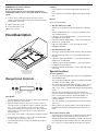
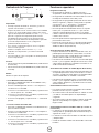
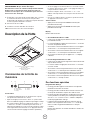
Hood Description
D
A
E
B
A. Blower and light controls
B. LED Lamps housings
C. Grease lter Handle
E. Grease lter
Range Hood Controls
A B C D E
A. Timer button
B. Light button
C. Display
D. - button
E. + button
Timer Button
• The default timer setting is 10 minutes, and it can be adjusted
between 20 minutes and 1 minute.
• After pressing the timer key, the control enters to a timer se
up mode, and user can adjust the timer countdown time with
the “-” and “+” keys within 5 seconds. The timer can be
initiated immediately pressing the timer key, after setting the
timer duration or pressing the timer key twice (default 10
minutes setting).
• If not action occurs within 5 seconds the countdown will start.
• During the timer setup the “-” and “+” keys are dedicated to
the timer and no motor action will occur.
• Once initiated the timer, it can be cancelled by pressing the
timer key again
Light Key
• Press lamp key to turn ON the light (Lamp state previously
OFF).
• Press lamp key to turn OFF the light (Lamp state previously
ON).
Display
Shows the hood settings.
“-” Key. Speed Decrease / OFF
• This key is used to decrease the fan speed, or turn OFF the
fan.
• The fan will turn OFF if the “-” key is pressed and the hood
was in the rst speed.
• If the fan is at second speed and the “-” key is pressed, the
fan will be set to rst speed.
• If the fan is at third speed and the “-” key is pressed, the fan
will be set to second speed.
• If the fan is OFF and the “-” key is pressed, the control
backlight will light up.
“+” Key. Speed Increase / ON
• This key is used to increase the fan speed, or turn ON the fan.
• The fan will turn ON if the “+” key is pressed and the hood
was OFF.
• If the fan is at rst speed and the “+” key is pressed, the fan
will be set to second speed.
• If the fan is at second speed and the “+” key is pressed, the
fan will be set to third speed.
• If the fan is at third speed and the “+” key is pressed, a beep
will sound.
Special functions
Clock programming
• The clock can be reprogrammed at any time except during an
active timed function.
• The clock can be displayed in a twelve hour format and valid
clock times are from 1:00 to 12:59.
• The clock can be reprogrammed pressing the “Timer” key for
5 seconds, and after, the clock can be adjusted with the “+”
and “-” keys. Colon “:” will ash indicating clock programming
mode.
• The user can have minute increments / decrements of 1
minute, but if the user keep pressing the “+”/”-” keys for more
than 1 second, the increments / decrements will be of 5
minutes. During this option the control will round to the
nearest 5 minutes.
• The user can nish on reprogramming the clock pressing the
“timer” key.
• After 1 minute of no key pressed the control will accept the
programmed clock time and will add one minute to the set
clock.
Grease lter saturation alarm
• After thirty fan functional hours, the display will show “Grease
Filter” if the fan is active. When this icon is shown in the
display, the grease lters installed are required to be washed.
• To reset the grease lter saturation alarm the user must press
the “+” key for 5 seconds, after this action the icon “grease

10
lter” is not display, and the hood has the normal display
operation.
Charcoal lter saturation alarm (Recirculating accessories)
• After one hundred and twenty functional hours of the fan, the
display will show “Charcoal Filter” if the fan is active. When
this icon ashes on display, the charcoal lters installed are
required to be replaced or reactivated.
• To reset the grease lter saturation indication the user must
press the “-” key for 5 seconds, after this time the icon
“charcoal lter” is not display and the hood has the normal
display operation.
Audible signal activation and deactivation
• The audible signals can be activated or deactivated pressing
the “Light” key for 5 seconds.
• If the audible signal is activated, a tone must sound and the
“Snd” symbol must appear on the display for 2 second.
• If the audible signal is deactivated, the “Snd” symbol must
appear on the display for 2 second and no sound must
sound.
Charcoal lter inclusion and exclusion (Recirculating
accessories)
• The charcoal lter inclusion or exclusion can be set by
pressing the “-” and “+” keys at the same time for 5 seconds.
• The Inclusion or exclusion of charcoal lter must be selected
while the lamps and the motor are OFF.
• When the charcoal has been excluded, the charcoal lter
alarm is disabled.
Heat sensor
• The control is equipped with a heat sensor that will turn on
the blower at second speed if excessive heat occurs (over
70°C) surrounding the control area.
• If the blower is OFF or if it is operating at rst speed, the
blower will be set automatically to second speed.
• During this state, the user may raise the blower speed to third
speed but can not decrease the speed.
• When the temperature level on the hood drops to normal, the
blower will operate in the setting dened by the user before
the alarm occured.
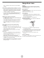
Range Hood Care
Cleaning
IMPORTANT: Clean the hood and grease lters frequently
according to the following instructions. Replace grease lters
before operating hood.
Exterior Surfaces:
To avoid damage to the exterior surface, do not use steel wool or
soap-lled scouring pads.
Always wipe dry to avoid water marks.
Cleaning Method:
• Liquid detergent soap and water, or all-purpose cleanser
• Wipe with damp soft cloth or nonabrasive sponge, then rinse
with clean water and wipe dry.
• Do not use cleaning agents containing bleach.
Aluminum Grease Filter:
1. Remove the lter by pulling the spring release handle and
then pulling down the lter.
A
A. Spring release handle
2. Wash aluminum grease lters as needed in dishwasher
or hot detergent solution.
3. Reinstall the lter by making sure the spring release handles
are toward the front. Insert aluminum lter into upper track.
4. Push in spring release handle.
Push up on aluminum lter and release handle to latch
into place.
Replacing a LED Lamp
The LED lights are replaceable by a service technician only. See
the service contact information in the next page.


Parts and Service Warranty:
For the period of one year from the date of the original purchase, we will provide free of charge, non consumable parts or components
that failed due to manufacturing defects. During this one year limited warranty, we will also provide, free of charge, all labor and in-
home service to replace the defective part.
What is Not Covered:
• Damage to the product caused by oods, act of God, re and accidents.
• Damage caused after delivery.
• House fuses replacement or resetting of circuit breakers.
• Service trips to your home to teach you how to use or install the product.
• Light bulbs, metal, carbon lters and the other consumable parts.
• The natural wear of nish, and wear due to improper maintenance, use of corrosive and abrasive cleaning
products, pads, and oven cleaner products.
This warranty will be voided when:
• Product damaged due to improper installation and failure to follow installation instructions, delivery or maintenance.
• Incidental or consequential damage caused by possible defects with this appliance.
• Alteration or modication of the Product which may cause in damage to the Product, or failure to operate it
in accordance with specications.
• Damage because of improper connection with equipment of other manufacturers.
• Failure of the product if it is negligence, abused, misused, or used for other than the intended purpose or used commercially.
• Improper repair, modication or servicing of the Product performed by third parties other than Authorized Agents.
Who is Covered:
This warranty is extended to the original purchaser for products purchased for ordinary home use in the 48 mainland states, Hawaii,
Washington D.C. Alaska, Guam, Puerto Rico and the Virgin Islands.
This warranty is non-transferable and applies only to the original purchaser and does not extend to subsequent
owners of this product. This warranty is made expressly in lieu of all other warranties, expressed or implied,
including, but not limited, any implied warranty of merchantability or tness for a particular purpose, and all other
obligations on the part of Elicamex, provided, however, that if the disclaimer of implied warranties is ineffective under applicable law,
the duration of any implied warranties arising by operation of law shall be limited to 1 (one) year from the date of original purchase at
retail or such longer period as may be required by applicable law.
This warranty does not cover any special, incidental and/or consequential damages, nor loss of prots, suffered by
the original purchaser, its customers and/or the users of the Product.
Have your product proof of purchase with date ready for warranty issues.
Or write to:
Who to contact
To obtain service under warranty or for any service related question, please visit the support section on the website below:
www.elica.com
Have your product proof of purchase with date ready for warranty issues.
TO OBTAIN SERVICE UNDER WARRANTY:
or any Service Related Questions, please call:
1-888-732-8018
Staple your receipt here.
Proof of the original purchase
date is needed to obtain service
under the warranty.
TO OBTAIN SERVICE UNDER WARRANTY: You must present proof of original purchase date.
Please keep a copy of your dated proof of purchase (sales slip) in order to obtain service under warranty.
WARRANTY

13
Tabla de Contenidos
Instrucciones Importantes de Seguridad............................ 13
Herramientas y Piezas........................................................... 14
Dimensiones del Producto.................................................... 15
Requisitos Eléctricos............................................................. 15
Requisitos de Ventilación...................................................... 15
Métodos de Ventilación......................................................... 15
Instrucciones de Instalación................................................. 16
Conexión Eléctrica................................................................. 19
Descripción de la Campana.................................................. 19
Cuidado de la Campana........................................................ 21
Garantía.................................................................................. 23
APROBADO PARA APARATOS DE USO DOMÉSTICO
SÓLO PARA USO DOMÉSTICO
LEA Y GUARDE ESTAS INSTRUCCIONES
ANTES DE CONTINUAR, LEA LAS INSTRUCCIONES POR
COMPLETO.
LA INSTALACIÓN DEBE CUMPLIR CON TODA LA
NORMATIVA LOCAL.
IMPORTANTE: Guarde estas instrucciones para su uso por
parte del inspector de electricidad local.
INSTALADOR: Entregue al propietario estas instrucciones con
la unidad.
PROPIETARIO: Conserve estas instrucciones para futuras
consultas.
Advertencia de Seguridad: Antes de realizar el cableado de este
aparato, desactive el circuito de energía eléctrica en el panel de
servicio y desbloquee el panel.
Requisito: Circuito Auxiliar de R120 VAC, 60 Hz. 15 ó 20 A
INSTRUCCIONES IMPORTANTES DE SEGURIDAD
ADVERTENCIA: PARA REDUCIR EL RIESGO DE INCENDIOS,
CHOQUE ELÉCTRICO O LESIONES A PERSONAS, OBSERVE
LO SIGUIENTE:
■ Use esta unidad sólo de la manera para la que fue diseñada
por el fabricante. Si tiene preguntas, póngase en contacto
con el fabricante.
■ Antes de dar servicio o limpiar la unidad,apague el suministro
de energía en el panel de servicio y bloquee los medios
de desconexión del servicio para evitar que se encienda
accidentalmente el suministro de energía. Cuando el medio
de desconexión del servicio no se pueda bloquear, sujete de
manera segura un dispositivo de advertencia prominente,
como podría ser una etiqueta, al panel de servicio.
■ La instalación y el cableado se debe llevar a cabo por una
persona(s) calicada(s), de acuerdo con los códigos y
estándares aplicables, incluida la construcción ignífuga.
■ Es necesaria una ventilación suciente para la correcta
combustión y expulsión de gases por la salida de humos
(chimenea) del equipo de combustión de carburante para
evitar el contratiro. Siga las directrices de fabricantes de
equipos de calefacción y los estándares de seguridad como
los publicados por la National Fire Protection Association
(NFPA), American Society for Heating, Refrigeration and Air
Conditioning Engineers (ASHRAE) y las normativas locales.
■ Al efectuar oricios en una pared o techo, no dañe el
ecableado eléctrico y otras instalaciones ocultas.
■ Los conductos deben tener ventilación con salida al exterior.
CUIDADO: Para usarse sólo en ventilación común. No lo use
para ventilar materiales y vapores peligrosos o explosivos.
CUIDADO: Para reducir el riesgo de incendio y para ventilar el
aire adecuadamente, asegúrese de dirigir el conducto de
ventilación hacia el exterior - no ventile el aire de salida a
espacios dentro de paredes o techos, áticos, espacios
angostos o garajes.
ADVERTENCIA: PARA REDUCIR EL RIESGO DE INCENDIO,
SÓLO USE CONDUCTOS METÁLICOS.
ADVERTENCIA: PARA REDUCIR EL RIESGO DE INCENDIO
PROVOCADO POR GRASA EN LA SUPERFICIE DE LA ESTUFA:
■ Nunca deje las unidades de supercie sin vigilancia cuando
estén en ajustes altos. La cocción puede causar humo o
reboses de grasa que pueden prender fuego. Caliente el
aceite a fuego lento o medio.
■ Siempre ENCIENDA la campana cuando cocine con calor
alto o cuando amee alimentos (por ejemplo, crepes Suzette,
cerezas Jubileo y ameado de carne de res con pimienta).
■ Limpie los ventiladores con frecuencia. No permita que la
grasa se acumule en el ventilador o en el ltro.
■ Use un tamaño de sartén adecuado. Siempre use utensilios de
cocción que sean los adecuados para el tamaño del elemento
de la supercie.
ADVERTENCIA: PARA REDUCIR EL RIESGO DE LESIONES A
PERSONAS SI SE PRENDE FUEGO EN LA SUPERFICIE DE LA
ESTUFA OCASIONADO POR GRASA, OBSERVE LO SIGUIENTE:
a
■ EXTINGA LAS LLAMAS con una tapa que encaje bien, una
bandeja para galletas o una bandeja metálica y luego apague
el quemador. TENGA CUIDADO PARA EVITAR QUEMADURAS.
Si las llamas no se extinguen de inmediato, EVACUE Y
LLAME AL DEPARTMENTO DE BOMBEROS.
■ NUNCA TOME UNA CACEROLA QUE ESTÉ ARDIENDO -
podría quemarse.
■ NO UTILICE AGUA, incluyendo paños para vajilla o toallas
mojadas - podría ocurrir una explosión de vapor violenta.
■ SÓLO use un extinguidor si:
-Sabe a ciencia cierta que tiene un extinguidor de clase
ABC y ya sabe cómo utilizarlo.
– El incendio es pequeño y se encuentra contenido en el
lugar en donde se inició.
– Ha llamado al departamento de bomberos.
– Puede apagar el fuego con su espalda mirando hacia una
una salida.
a
Basado en “Consejos de seguridad para fuegos se cocina”
publicado por NFPA.
ADVERTENCIA: A n de reducir el riesgo de incendio
o de choque eléctrico, no use este ventilador con ningún
dispositivo semiconductor para el control de la velocidad.
LEA Y GUARDE ESTAS INSTRUCCIONES

14
Herramientas y Piezas
Piezas Suministradas
Remoción del empaque
CUIDADO
Quite la caja cuidadosamente, use guantes para protegerse
contra los bordes alados.
ADVERTENCIA
Quite la película de protección que cubre el producto antes
de ponerlo en funcionamiento.
• Ensamblaje del escudete para campana con ventilador y
lámparas LED previamente instaladas
• Ducto de escape redondo de metal de 6” (15.2 cm)
• Filtros de grasa
• Bolsa plástica con el siguiente contenido:
Pieza Cantidad Pieza Cantidad
5x45 mm
4
Adaptador Torx 20
1
4.5x13 mm
4
Taquetes de 10 x 60 mm
4
3.5x9.5 mm
2
Tornillos 5.4x75 mm
(para los taquetes de
10x60 mm)
4
Adaptador Torx 10
1
Herramientas/Materiales requeridos
• Nivel
• Taladro con brocas de 1¼” (3.2 cm),
1
⁄8” (3.2 mm), y
1
⁄16” (4,8 mm)
• Lápiz
• Pelacables o cuchillo de uso general
• Cinta de medir o regla
• Pinzas
• Pistola para calafateo y masilla para calafateo a prueba de agua
• Abrazaderas para ducto de ventilación
• Sierra de vaivén o sierra caladora
• Destornillador de hoja plana
• Tiijeras de hojalatero
• Destornillador Phillips
Piezas necesarias
• Cable de suministro eléctrico doméstico
• Protector de cables de ½” (12.7 mm) que esté en la lista de
UL o aprobado por CSA
• 3 conectores para cables que estén en la lista de UL
Para instalaciones con ducto de escape, también necesitará:
• 1 cubierta para pared o techo
• Sistema de ventilación metálico
Piezas no suministradas
Accesorios Opcionales
Kit # Pieza Kit # Pieza
Válvula de
no reterno
KIT0102873 Recirculante 30” KIT01939
36” KIT01940
Cubierta de
cubreducto
6”H
30” KIT01941
36” KIT01942
Cubierta de
cubreducto
12”H
30” KIT01944
36” KIT01945
Reducción
CFM
KIT02748 Filtro de
grasa
KIT01668
Dimensiones del Producto
F
M
D
C
B
A
E
H
G
I
Altura del Kit
Recirculante
J
Altura del kit de la
cubierta del conducto
K (6”)
L (12”)
ALZ430SSA ALZ436SSA
A 30” (76 cm) 36” (91.54 cm)
B 23
7
⁄64” (58.7 cm)
C 17
63
⁄64” (45.7 cm)
D 12
3
⁄64” (30.6 cm)
E 2
10
⁄32” (5.9 cm)
F 29
4
⁄32” (74 cm) 35
7
⁄32”(89.5 cm)
G 7
3
⁄32” (18 cm)
H 2
9
⁄16” (6.5 cm)
I
13
⁄32” (1 cm)
J 21
59
⁄64 (55.7 cm)
K 23
15
⁄16 (60.8 cm)
L 29
59
⁄64 (76 cm)
M 6" (15.24 cm)

15
Requisitos Eléctricos
IMPORTANTE
Observe todos los códigos y reglamentos aplicables.
Es la responsabilidad del propietario:
Contactar un instalador eléctrico calicado.
Asegurarse de que la instalación eléctrica es adecuada y en
conformidad con National Electrical Code, ANSI/NFPA 70
— última edición* o CSA Standards C22.1-94, Canadian
Electrical Code, Parte 1 y C22.2 No.0-M91 — última edición**
y toda la normativa y las ordenanzas locales.
Si la normativa lo permite y se utiliza un cable de toma a tierra
independiente, se recomienda que un electricista calicado de-
termine si la difracción de onda de tierra es la adecuada.
Una copia de las normas que se mencionaron anteriormente, se
pueden obtener de:
National Fire Protection Association
1 Batterymarch Park
Quincy, MA 02169-7471
CSA International
8501 East Pleasant Valley Road
Cleveland, OH 44131-5575
■ Se necesita un circuito eléctrico de 120 voltios, 60 hertzios,
CA solamente, de 15 amperios y protegido con fusibles.
■ Si la casa tiene cableado de aluminio, siga el procedimiento a
continuación:
1. Conecte una sección de alambre de cobre sólido a los
conductores exibles.
2. Conecte el cableado de aluminio a la sección añadida de
alambre de cobre usando conectores especiales y/o
herramientas diseñadas y de la lista de UL para unir el cobre
al aluminio.
■ Siga el procedimiento recomendado por el fabricante del
conector eléctrico. La conexión de cobre/aluminio deberá
hacerse en conformidad con los códigos locales y las
prácticas de cableado aceptadas por la industria.
■ Los tamaños de los cables y las conexiones deben cumplir
de acuerdo con la clasicación del electrodoméstico, como
se especica en la placa de clasicación del modelo/de la
serie. La placa del modelo/de la serie está ubicada detrás del
ltro, en la pared posterior de la campana para cocina.
■ El tamaño de los cables debe cumplir con los requisitos del
National Electrical Code (Código Nacional Eléctrico), ANSI/
NFPA 70 (última edición) o las normas de CSA C22. 1-94
Canadian Electrical Code (Código Canadiense de
Electricidad), Parte 1 y C22.2 N° 0-M91 (última edición),
y todos los códigos y ordenanzas locales.
Requisitos de Ventilación
(Modelos con ducto de escape solamente)
• El sistema de ventilación debe terminar en el exterior, excepto
para las instalaciones sin ducto de escape (con recirculación).
• No dirija la salida del sistema de ventilación hacia el desván u otra
área cerrada.
• No utilice una cubierta de pared de tipo para lavandería de
4” (10,2 cm).
• Utilice ducto de escape de metal únicamente. Se recomienda
un ducto de escape de metal rígido. No se recomienda ducto
de escape de plástico u hoja metálica.
• El largo del sistema de ventilación y el número de codos
se deben mantener al mínimo para proveer un funcionamiento
ecaz.
Para obtener el funcionamiento más ecaz y silencioso:
• No use más de 3 codos de 90°.
• Asegúrese de que haya un mínimo de 24” (61 cm) de ducto
de escape recto entre los codos, si se utiliza más de 1 codo.
• No instale 2 codos lado a lado.
• Use abrazaderas para sellar todas las juntas en el sistema de
ventilación.
• El sistema de ventilación debe tener una compuerta. Si la
cubierta del techo o la pared tiene una compuerta, no use la
compuerta provista con la campana de cocina.
• Utilice masilla de calafateo para sellar la abertura exterior de la
pared o el techo alrededor de la cubierta.
• El tamaño del ducto de escape debe ser uniforme.
Instalaciones en climas fríos
Una válvula de no retorno adicional debe ser instalada para
reducir el ujo de aire frío como parte del sistema de ventilación.
Un break térmico debe ser instalado para reducir la conducción
de las temperaturas exteriores al interior del sistema de
ventilación.
La válvula deberá estar en el lado del aire frío del break térmico.
Reguladores de aire
Los códigos de construcción local sugieren el uso de sistemas
reguladores de aire cuando se usen sistemas de ventilación
mayores a la CFM especicada o al movimiento del aire. El CFM
especicado varía dependiendo del área. Consulte a un técnico
en ventilación para conocer los requerimientos de su área.
Métodos de Ventilación
Esta campana con escudete se ha ajustado de fábrica para tener
una ventilación a través del techo (descarga vertical) o de la
pared (descarga horizontal). Se requiere un sistema de ventilación
redondo de 6” (15,2 cm) para la instalación (no incluido).
NOTA: No se recomienda el uso de ductos de escape exibles.
Los ductos de escape exibles crean contrapresión y turbulencia
de aire, lo cual reduce el desempeño en gran medida. El sistema
de ventilación debe terminar a través del techo o la pared. Para
colocar el ducto a través de la pared, se necesita un codo de 90°.
Para las instalaciones sin ducto de escape
(con recirculación)
Si no es posible ventilar el humo y los vapores de la cocción
al exterior, la campana puede usarse en la versión reciruclante
utilizando el kit recirculante. Vea la sección de accesorios opcio-
nales.
Preparación
No corte una vigueta o un perno a menos que sea absolutamente
necesario. Si fuera necesario efectuar el corte, deberá
construirse un marco de soporte.
Se suministra el material de ajuste necesario para jar la campa-
na a la mayoría de tipos de muro o techo.

16
No obstante, un técnico cualicado debe comprobar la idoneidad
de los materiales de acuerdo con el tipo de muro o techo.
Antes de efectuar ningún corte, asegúrese de existe espacio libre
adecuado en el techo o muro para la expulsión del aire.
La preferencia de la altura de instalación de la campana de los
usuarios es por encima de la cocina. Cuanto más cerca esté la
campana de la cocina, más ecaz resultará la captura de olores,
grasa y humos.
PRECAUCIÓN: instale esta campana de tal manera que la
cornisa inferior se encuentre a 30" (76,2 cm) sobre la supercie
de cocción. Para la instalación de estufas eléctricas: instale esta
campana de tal manera que la cornisa inferior se encuentra a
no menos de 24" (61 cm) y no más de 30" (76,2 cm) sobre la
supercie de cocción. Para uso electrodoméstico. Por favor, lea
el manual de instalación para una instalación especíca.
Antes de seleccionar la campana, compruebe la altura del techo
y la altura máxima de la campana.
Ventilación a través de techo Sin ducto de escape
(con recirculación)
A
B
C
F
F
C
E
Ventilación a través de pared
F
A
B
D
F
C
A
B
A. Transición redonda de 6”
B. Sistema del conducto redondo de 6”
C. Cabinet / Duct cover kit
D. Codo 90°
E. Kit recirculante
F. Altura de la instalación:
Rango de la estufa MÍN: 30” (76.2 cm)
Rango eléctrico: desde 24” (61 cm ) hasta
30” (76.2 cm)
Instrucciones de Instalación
Versión con ducto de escape
Después de haber escogido la opción de descarga, proceder
como sigue:
• Prepare el ducto y cortes necesarios.
• Si es posible, desconecte y deslice la estufa fuera de la
apertura de instalación del gabinete de la cocina para permitir
un acceso fácil al muro posterior.
De lo contrario, coloque una cubierta protectora gruesa sobre
la cubierta o la estufa para protegerla de daños o suciedad.
Seleccione una supercie plana para montar la unidad.
Coloque una cubierta protectora sobre la supercie y coloque
en ella todas las piezas de la carcasa de la campana, tornillos
y elementos metálicos.
• Determine y marque la línea central en el muro donde se
instalará la carcasa de la campana. Seleccione una altura
de montaje confortable para el usuario y realice una marca en
el muro situado detrás de la cocina.
• Prepare el conducto y corte lo necesario.
• Quitar los precortes del conducto usando un destornillador
plano y un martillo pequeño. De unos pequeños golpes para
remover la cubierta, utilizando el martillo y destornillador de
forma similar a la que se hace con un cincel.
• Tenga cuidado con los los cortantes.
A
B
A. Descarga vertical
B. Descarga horizontal
• Fijar la transición redonda de 6" sobre la apertura del precorte
con 2 tornillos de 3.5 x 9.5 mm.
A
C
C
B
A. Transición redonda de 6” (instalación de la descarga vertical)
B. Transición redonda de 6” (instalación de la descarga horizontal)
C. 2 tornillos de 3.5 x 9.5 mm para la instalación

17
NOTA: La transición se puede colocar hasta 1” del centro de
la campana para acomodarse a instalaciones descentradas.
En instalaciones extremadamente descentradas, un lado de la
transición deberá ser recortada para evitar interferencias con la
abrazadera del cable.
Marcar los oricios
Seleccionar la opción de descarga que requiere su
instalación y proceder a esa sección:
Extractor superior al exterior
Usar el diagrama o la campana como plantilla y marcar los puntos en
el gabinete para el trabajo del conducto, la instalación eléctrica y las
ranuras del tornillo de la cerradura.
35
⁄64”
(1.4 cm)
Oricio de acceso
eléctrico (en la parte
inferior del gabinete)
Tornillos de
montaje (4)
6
17
⁄64”
(15.9 cm)
Tiras de
madera
LÍNEA
CENTRAL
Parte frontal
del gabinete
7
3
⁄32”
(18 cm)
2
19
⁄32”
(6.6 cm)
13
⁄32”
(1 cm)
1
11
⁄16”
(4.3 cm)
10
37
⁄64”
(26.86 cm)
Ø
55
⁄64”
(2.2cm)
1
47
⁄64”
(4.4 cm)
Parte inferior del gabinete
4
7
⁄32”
(10.7cm)
4
7
⁄32”
(10.7cm)
Oricio de
acceso para
ducto
Sólo para gabinetes huecos
Si los gabinetes tienen perles frontales, laterales o posteriores, hacer
2 soportes de madera con el ancho del perl y ensámblelos a ambos
lados de la parte inferior del gabinete.
Tiras de
madera
Extractor posterior exterior
(Conducto horizontal Ø 6” (15.2 cm))
Usar el diagrama o la campana como plantilla y marcar los puntos en
el gabinete para el trabajo del conducto, la instalación eléctrica y las
ranuras del tornillo de la cerradura.
4
7
⁄32”
(10.7cm)
1
27
⁄64”
(3.6cm)
4
27
⁄32”
(12.3cm)
4
61
⁄64”
(12.6cm)
9
⁄32”
(0.7cm)
4
7
⁄32”
(10.7cm)
6
17
⁄64”
(15.9cm)
3
25
⁄32”
(9.6cm)
6
57
⁄64”
(17.5cm)
6
57
⁄64”
(17.5cm)
1
11
⁄16”
(4.3cm)
1
1
⁄16”
(2.7cm)
55
⁄64”
(2.2cm)
1
37
⁄64” (4 cm)
1. Remueva los ltros de grasa.
2. Retire los tornillos de instalación del motor. Ponga los
tornillos en un lugar seguro con el n de usarlos de nuevo.
3. Libere los dos clips de sujeción del motor de la parte superior
de la campana.
4. Voltee la base del motor a la cara posterior de la campana.
5. Inserte los dos clips de sujeción del motor a la parte posterior
de la campana. Asegure el motor con los 4 tornillos
previamente retirados.

18
Montaje de la Campana
Instalación a la pared
Instalación de la estructura de soporte para la campana
1. Marque las ubicaciones de los oricios de los tornillos
indicados en la gura de “Outside rear exhaust”.
2. Si se cuenta con pared falsa (cartón yeso), remueva (corte)
lo suciente de pared para posicionar 2 postes verticales en
la ubicación de los agujeros referenciados en el punto anterior
con ayuda de la plantilla. Instale dos soportes horizontales
entre dos postes de la pared, en donde deberán ir
posicionados los agujeros inferiores y superiores.
3. El soporte horizontal debe ser nivelado con el lado de la
habitación con los postes de la pared. Use grapas detrás de
ambos lados del soporte para asegurar los tabiques.
4. Reinstale la pared falsa (cartón yeso), resane y termine.
Vista posterior
Soporte de
montaje
Línea central
del espacio
de instalación
IMPORTANTE: La estructura debe ser
capaz de soportar 100 lbs.
Abrazadera
5. Cortar los oricios en los lugares marcados para conductos y
cableado eléctrico.
Montando la campana
1. Inserte un tornillo de instalación al centro de la parte angosta
de los oricios de instalación marcados en la parte baja del
gabinete o la pared.
NOTA: debe tener en cuenta el material de las paredes de la
construcción con el n de elegir el anclaje de pared adecuado y
el tornillo. Para paredes de madera contrachapada debe utilizar
los anclajes de pared de 10 mm x 60 y los tornillos 5.4x75 mm.
Para muros de concreto que debe utilizar los tornillos de 5x45 mm.
2. Instale las 2 piezas de acuerdo a los tornillos seleccionados
sobre la ubicación de los tornillos de montaje (Vea imagen).
Deje la cabeza del tornillo despegada aprox.
1
⁄4” (6.4 mm) de
la base para deslizar la campana en su lugar.
1
⁄4”
(6.4 mm)
3. Fijar el conducto de cableado de la campana.
4. Deslice la parte trasera de la campana contra la pared. Ajuste
los tornillos de montaje. Asegúrese de que la cabeza de los
tornillos estén en la parte angosta de los oricios de instalación.
A
B
A. Tornillos de montaje
B. Tornillos inferiores de seguridad (Instalación de pared)
5. Drive 2 pieces of the selected screws in the lower security
screws location (see the image above).
6. Una el tubo a la campana.
Instalación del gabinete
NOTA: Su gabinete debe ser capaz de soportar al menos
88 lb (40 kg).
7. Inserte un tornillo de instalación al centro de la parte angosta
de los oricios de instalación marcados en la parte baja del
gabinete o la pared.
8. Instale 4 tornillos de instalación de 4 x 8 mm. Deje la cabeza
del tornillo despegada aprox.
1
⁄4” (6.4 mm) de la base para
deslizar la campana en su lugar.
1
⁄4”
(6.4 mm)
9. Fijar el conducto de cableado de la campana.
10. Deslice la parte trasera de la campana contra el gabinete.
Ajuste los tornillos de montaje. Asegúrese de que las cabeza
de los tornillos estén en la parte angosta de los oricios de
instalación.
A
A. Tornillos de montaje

19
Conexión Eléctrica
ADVERTENCIA: Peligro de Choque Eléctrico
Desconecte el suministro de energía antes de darle
mantenimiento.
Vuelva a colocar todos los componentes y paneles antes de
hacerlo funcionar. No seguir estas instrucciones puede
ocasionar la muerte o choque eléctrico.
1. Desconecte el suministro de energía.
2. Retire la caja de terminales.
3. Quite el disco removible que está en la caja de terminales e
instale un protector de cables de
1
⁄2” que esté en la lista de
UL o esté aprobado por CSA.
C
B
A
A. Caja de Terminales
B. Disco Removible
C. Cubierta de la caja de terminales
4. Haga pasar el cableado de suministro de energía doméstico a
través del protector de cables, dentro de la caja de terminales.
A
B
F
C
E
D
A. Cable de suministro de energía doméstico
B. Protector de cables que esté en la lista
de UL o aprobado por CSA
C. Alambres negros
D. Conectores de alambres aprobados por UL
E. Alambres blancos
F. Alambres verdes (o desnudos) y amarillos -
verdes de puesta a tierra
5. Use conectores de alambres que estén en la lista de UL y
conecte los alambres negros (C) juntos.
6. Use conectores de alambres que estén en la lista de UL y
conecte los alambres blancos (E) juntos.
ADVERTENCIA: Peligro de Choque Eléctrico
Conecte el soplador a tierra.
Conecte el alambre de tierra al alambre verde y amarillo de
conexión a tierra en la caja de terminales.No seguir estas
instrucciones puede ocasionar la muerte o choque eléctrico.
7. Conecte el alambre verde (o desnudo) de puesta a tierra del
suministro de energía doméstico al alambre amarillo - verde
de puesta a tierra (F) en la caja de terminales usando
conectores de alambres que estén en la lista de UL.
8. Apriete el tornillo del protector de cables.
9. Instale la cubierta de la caja de terminales.
10. Reconecte el suministro de energía.
Descripción de la Campana
D
A
E
B
A. Controles de la luz y del soplador de la campana
B. Luces LED
C. Manija del ltro de grasa
E. Filtro de grasa

20
Controles de la Campana
A B C D E
A. Temporizador
B. Botón de luz
C. Pantalla
D. Botón -
E. Botón +
Temporizador
• El tiempo ajustado de default es 10 minutos y puede ser
ajustado entre 20 minutos y 1 minuto.
• Después de pulsar la tecla, el sistema entra en la modalidad
de ajuste y el usuario puede ajustar el tiempo de la cuenta
regresiva del temporizador utilizando las teclas “-” y “+“ en un
plazo de 5 segundos. El temporizador puede iniciarse
inmediatamente presionando la tecla del temporizador,
después de ajustar la duración del temporizador o pulsando
la tecla del temporizador dos veces (conguración
predeterminada de 10 minutos).
• Si no se lleva a cabo ningún ajuste en estos 5 segundos,
inicia la cuenta regresiva.
• Durante el setup del “Timer” las teclas “+” y “-“ son
dedicadas a la temporización y no varian la velocidad
del motor.
• Una vez inciado el conteo, este puede ser anulado pulsando
la tecla “Temporizador”.
Tecla Luz
• Pulsar el botón de luz para ENCENDER la luz (estado anterior
de la luz OFF).
• Pulsar el botón de luz para APAGAR la luz (estado anterior de
la luz ON).
Pantalla
Muestra los ajustes de la campana.
“-” Tecla Disminución Velocidad / OFF
• Esta tecla es utilizada para reducir la velocidad del motor y
para apagar la campana.
• El motor se APAGA pulsando la tecla “-“ si la campana se
encuentra en la 1° velocidad.
• Si el motor se encuentra en la 2° velocidad y se pulsa la tecla
“-“, el motor pasa en la 1° velocidad.
• Si el motor se encuentra en la 3° velocidad y se pulsa la tecla
“-“,el motor pasa en la 2° velocidad.
• Si el motor está apagado y se pulsa la tecla “-“, se ilumina la
pantalla.
“+” Tecla Incremento Velocidad / ON
• Esta tecla es utilizada para aumentar la velocidad del motor y
para encender la campana.
• El motor se enciende pulsando la tecla “+“ si la campana se
encuentra en el estado OFF.
• Si el motor se encuentra en la 1° velocidad y se pulsa la tecla
“+“, el motor pasa en la 2° velocidad.
• Si el motor se encuentra en la 2° velocidad y se pulsa la tecla
“+“, el motor pasa en la 3° velocidad.
• Si el motor se encuentra en la 3° velocidad y se pulsa la tecla
“+“, se emite un “beep”.
Funciones especiales
Programación del reloj
• El reloj puede ser ajustado en cualquier momento a
excepción de cuando está activada la función temporizador.
• El reloj puede ser visualizado en el formato de doce horas con
un tiempo de visualización entre 1:00 y 12:59.
• El reloj puede ser reprogramado presionando la tecla “Timer”
durante 5 segundos, y después, el reloj puede ser ajustado
con las teclas “+” y “-”. Dos puntos “:” se iluminará,
indicando el modo de la programación del reloj.
• El usuario puede aumentar/disminuir la hora con step de1
minuto, pero si se pulsan las teclas “+”/”-“ por más de 1
segundo el aumento/disminución acontece con step de
5 minutos. Durante dicha operación el control redondea a los
5 minutos más cercanos.
• El usuario puede terminar la reprogramación del reloj,
presionando la tecla “timer”.
• Después de 1 minuto de que no se haya presionado ninguna
tecla, el control aceptará el tiempo del reloj programado y
añadirá un minuto al ajuste del reloj.
Señal de Saturación del Filtro de Grasa
• Después de treinta horas de funcionamiento del motor, en la
pantalla aparecerá la indicación “Grease Filter”, en caso de
que esté el motor activo. Cuando aparece esta señal en la
pantalla, el ltro instalado necesita ser lavado.
• Para reiniciar la señal de ltro de grasa, el usuario debe pulsar
la tecla “+” por 5 segundos, después de esta acción, la señal
“Grease Filter” desparecerá y la pantalla se mostrará con su
estado normal de funcionamiento.
Señal Saturación del Filtro de Carbón (Opción Recirculante)
• Después de ciento veinte horas de funcionamiento del motor,
en la pantalla aparecerá la señal “Charcoal Filter” si el motor
está activo. Cuando esta señal aparece en la pantalla el ltro
carbón instalado debe ser cambiado o reactivado.
• Para reiniciar la señal de ltro grasas, el usuario debe pulsar
la tecla “-” por 5 segundos, después de esta acción, la señal
“Charcoal Filter” desaparece y la pantalla muestra el estado
del funcionamiento.
Activación/Desactivación señal acústica
• Las señales acústicas pueden ser activadas o desactivadas
pulsando la tecla “Luz” por 5 segundos.
• Si la señal acústica está activada, debe ser emitido un sonido
y el símbolo “Snd” debe aparecer en la pantalla por
2 segundos.
• Si la señal acústica está desactivada, el símbolo “Snd” debe
aparecer en la pantalla por 2 segundos y no es emitido
ningún sonido.
Activación/Desactivación señal ltro carbón (accesorios de
recirculación)
• La activación y la desactivación de la señal saturación ltro
carbón puede ser ajustada pulsando simultaneamente por 5
segundos las teclas “-“ y “+”.
• La activación o la desactivación debe ser realizada con motor
y lámparas OFF.
• Cuando la señal Filtro Carbón está desactivada, se desactiva
la alarma.
La page charge ...
La page charge ...
La page charge ...
La page charge ...
La page charge ...
La page charge ...
La page charge ...
La page charge ...
La page charge ...
La page charge ...
La page charge ...
La page charge ...
La page charge ...
La page charge ...
La page charge ...
La page charge ...
-
 1
1
-
 2
2
-
 3
3
-
 4
4
-
 5
5
-
 6
6
-
 7
7
-
 8
8
-
 9
9
-
 10
10
-
 11
11
-
 12
12
-
 13
13
-
 14
14
-
 15
15
-
 16
16
-
 17
17
-
 18
18
-
 19
19
-
 20
20
-
 21
21
-
 22
22
-
 23
23
-
 24
24
-
 25
25
-
 26
26
-
 27
27
-
 28
28
-
 29
29
-
 30
30
-
 31
31
-
 32
32
-
 33
33
-
 34
34
-
 35
35
-
 36
36


arietta ALZ430SSA Guide d'installation
- Catégorie
- Hottes
- Taper
- Guide d'installation
- Ce manuel convient également à
dans d''autres langues
- English: arietta ALZ430SSA Installation guide
- español: arietta ALZ430SSA Guía de instalación