
WARNING: Risk of electrical shock. New installation and LED Retrot Kit installation requires knowledge of sign electrical systems. If not qualied, do not attempt installation. Contact a qualied
electrician. Follow all NEC and local codes. SloanLED Prism
12
Nano+ is not suitable for submersion or direct exposure to water for extended periods of time. AVERTISSEMENT: Risque de choc
électrique. La nouvelle installation et l’installation du kit de modication à LED nécessitent la connaissance des systèmes électriques de signalisation. Si non qualié, ne tentez pas l'installation.
Contactez un électricien qualié. Suivez tous les codes NEC et locaux. SloanLED Prism
12
Nano+ ne convient pas à la submersion ni à l'exposition directe à l'eau pendant de longues périodes.
For New Installation, proceed with Step 1 below. For Retrot Installations, begin with Retrot Instructions on page 3.
New Installation
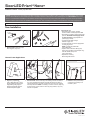
1. Optional tools: Measuring tape,
wire strippers, crimp tool.
2. Components list:
• SloanLED Prism12 Nano+ modules,
model numbers 701269-(XX)12NJ1-MB
• SloanLED 12 V Class 2 output power supply
(refer to "SloanLED Power Supply Guide
for Sign Products" for appropriate 12 V
power supply models).
• UL approved 18 AWG or larger
diameter supply wire.
• UL approved wire connectors appropriate
for wire gauge used.
NOTE: 701269-(XX)12NJ1-MB
has 22 AWG wire.
• Optional: 3M™ Scotchlok™ UR2 (3-port)
and UY2 (2-port) IDC connectors (EU only).
Use with 3M IDC Crimp Tool
(part number E-9J).
• Optional for mounting:
Electrical grade silicone.
Channel Letter Applications
CAN DEPTH
STROKE WIDTH
3.
Layout: To populate sign,
refer to SloanLED Prism12 Nano+
density guidelines as well as power
supply loading chart (page 4) to
determine appropriate number of
modules and power supplies.
4. Peel and stick: Clean inside sign with rubbing alcohol and allow to
dry. Using predetermined layout and LED placement from Step 3,
remove tape backing and stick modules into place. Ensure modules
are rmly attached. NOTE: If installing in a narrow channel, tape may
be unnecessary. Other means of securing strip (sealant, vinyl, etc.)
are also acceptable.
5. Fasteners: Use provided tape
or silicone as necessary to x
modules in place.
SloanLED Prism12 Nano+
Installation Guide for 701269-(XX)12NJ1-MB
PAGE 1 OF 4

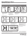
7. Cap all unused wires:
Using appropriate UL Listed
wire connectors (refer to
components list on page 1),
cap all unused wires. Strand of
modules should not be looped
to create a closed circuit.
8. Connect power supply to rst
module on string: See power
supply install guide for more
information regarding power
supply installation.
9. Replace sign face:
Clean any debris from inside of
sign and replace the sign face.
6. Connections: Modules may be
connected in series or parallel.
Tip: Discarding a module can
allow longer wire lengths for
connections.
WARNING: Connect Red striped wire of LED modules (+) to Red wire of power supply (+). Connect White wire of LED modules (-) to Black wire of power supply (-). Reverse polarity
connections may damage LEDs and will void product warranty. AVERTISSEMENT: Connectez le l rouge des modules LED (+) au l rouge de l'alimentation (+). Connectez le l blanc
des modules LED (-) au l noir de l'alimentation (-). Des connexions inversées peuvent endommager les DEL et annuler la garantie du produit.
* Based on using Evonik Plexiglass WM51, 30 mm, 23% light transmission. For any other type, testing is recommended for determining light transmission.
BlockLED Applications*
1a.
Preparing block: It is recommended to mill
down module mounting surface 0.43" (11 mm),
giving 0.08" - 0.12" (2-3 mm) space between
lens and back tray.
Module
mounting
surface
1b. Preparing block: Mill 0.31" (8 mm) wide
channel an additional 0.28" (7 mm) down
(0.71" [18 mm] total) to improve light
transmission around edges.
0.31"
(8 mm) wide,
0.71"
(18 mm) deep
1c. Preparing block: Maintain up to 0.31" (8 mm)
return and use block-out lm along return.
NOTE: Ensure adhesive layer on block-out
lm is white for optimum light reection and
uniform distribution on face.
Optional: Paint may be used instead of
block-out lm. Dierent color paints may
be used, as long as rst layer is white for
optimum light reection.
Return
3.
Connections: Follow steps 6 through 8 under
installation for Channel Letter Applications.
2. Module placement: Mount modules ~1.2" (30 mm) apart (center-to-center) using provided tape,
or silicone as necessary. NOTE: Avoid silicone on top of lenses.
~1.2" (30 mm) module center spacing
SloanLED Prism12 Nano+
Installation Guide for 701269-(XX)12NJ1-MB
PAGE 2 OF 4

1. Identify sign to be retrot and ensure branch circuit supplying existing sign are within voltage range for LED power supply.
Refer to components list (page 1) and "12 VDC Power Supply Capacity Chart" (page 4).
2. Remove existing lighting equipment intended to be replaced, such as neon or uorescent, and all power supplies, transformers, or ballasts.
Remove existing neon and all standos to leave an empty channel letter can. NOTE: All materials removed must be disposed of in accordance
with applicable local, state, and federal laws.
3. If required by local, state, or national electrical code, install a new disconnect switch.
4. Determine suitability and structural integrity of existing sign after removal of existing lighting equipment. If retrot does not require the making of
any new holes, do not make or alter any open holes in an enclosure of wiring or electrical components during kit installation. If existing holes are
present in a wet or outdoor location sign, repair and seal any unused openings in the electrical enclosure. Openings greater than 0.5" (12.7 mm)
diameter require a metal patch secured by screws or rivets and caulked with non-hardening caulk. Smaller openings may be sealed with non-
hardening caulk.
5. Clean inside of sign using non-oil based cleaner. Follow all manufacturer’s instructions and ensure inside of sign is dry before proceeding with
installation. This is an important step for good adhesion of SloanLED channel letter module mounting tape.
6. To populate sign, refer to SloanLED Prism12 Nano+ density guidelines as well as power supply capacity (page 4) to determine appropriate number
of modules and power supplies. A list of acceptable power supply models is shown in the supplemental "SloanLED Power Supply Guide for
Sign Products".
7. Follow all instructions under "New Installation" to properly install LED modules.
8. Connect modules to power supply output as shown under "New Installation".
9. Connect power supply input as outlined in power supply installation guide in accordance with local, state and national electrical codes by
qualied personnel. Refer to power supply install guide included with power supply for details.
10. If required, install disconnect switch in accordance with local, state and national electrical codes by qualied personnel.
Retrot Instructions for Existing Signs
WARNING: Risk of re or electric shock. Install this kit only in host signs that have been identied in the installation instructions, and
where the input rating of the retrot kit does not exceed the input rating of the sign. Installation of this LED retrot kit may involve drilling
or punching of holes into the structure of the sign. Check for enclosed wiring and components to avoid damage to wiring and electrical
parts. AVERTISSEMENT: Risque d’incendie ou de choc électrique. Installez ce kit uniquement sur les panneaux hôtes identiés dans
les instructions d'installation et dans lesquels les caractéristiques nominales d'entrée du kit de modication ne dépassent pas celles du
panneau. L’installation de ce kit d’amélioration des LED peut impliquer de percer ou de percer des trous dans la structure de l’enseigne.
Vériez le câblage et les composants inclus pour éviter d'endommager le câblage et les pièces électriques.
GENERAL PURPOSE
RETROFIT SIGN CONVERSION.
FOR USE ONLY IN ACCORDANCE
WITH KIT INSTRUCTIONS.
KIT IS COMPLETE ONLY WHEN ALL PARTS
REQUIRED BY THE INSTRUCTIONS ARE PRESENT.
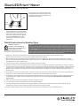
4.
Back tray: Replace and seal back tray. It is
important that back tray is completely sealed
to prevent water entry. It is also recommended
to add minimum 0.125" (3 mm) drain holes at
lowest points of sign as exits for any potential
water ingress.
NOTE: Ensure back tray
inside surface is matte white for optimum
light reection.
To populate sign, refer to SloanLED Prism12 Nano+
density guidelines as well as power supply loading
chart (page 4) to determine appropriate number of
modules and power supplies.
Back
tray
Drain
holes
SloanLED Prism12 Nano+
Installation Guide for 701269-(XX)12NJ1-MB
PAGE 3 OF 4

SloanLED Headquarters
5725 Olivas Park Drive, Ventura, CA, USA
888.747.4LED (888.747.4533) • info@SloanLED.com
SloanLED.com
SloanLED Europe b.v.
Argonstraat 110, 2718 SN Zoetermeer, NL
+31 88 12 44 900 • europe@SloanLED.com
P/N 402929 Rev A 2021-09-09
Customer service and technical support
241542
E215393
SloanLED Prism12 is covered by the following US patents issued: 6,932,495, 7,241,031.
Troubleshooting
NOTE: A licensed electrician should perform all applicable steps.
Entire sign or leg does not light
after complete installation
Check connection from power supply lead to rst module. Make sure polarity of connections made at the power supply lead and any jumper wire is
correct. Power supply outputs should be connected RED-TO-RED and BLACK-TO-WHITE.
Still does not light Check output voltage of power supply using a voltmeter. The output voltage should be DC 12.0 V ± 0.5 V. If there is no output voltage, have a
licensed electrician check input voltage. Make sure power supply is connected correctly and getting primary power. If power supply is connected
properly and getting primary power and there is still no output voltage, try a different power supply.
Still does not light If power supply is getting primary power and the modules don’t light, there may be a short in the secondary wiring.
Check all connections and cap all loose wires.
The beginning of a leg lights,
but the entire leg does not light
or lights intermittently
The primary cause of a portion of a SloanLED Prism12 Nano+ leg not lighting or lighting intermittently is a bad connection or reverse polarity
connection between the modules that light and the modules that don’t light. Check this connection.
One module does not light,
but all others in the leg light
SloanLED Prism12 Nano+ is designed so if one module fails, it will not cause the entire sign or leg to go out. If one module does not light, but all others
in the leg do, replace this module with a new one.
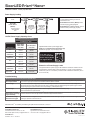
12 VDC Power Supply Capacity Chart
Maximum feet (meters) / modules
SloanLED Prism12 Nano+
Power output
White 7200 K,
6500 K, 5000 K,
4000 K, 3000 K
(7.6/ft, 25/m)
Red, Green, Blue
(7.6/ft, 25/m)
20 W 10.9 (3.3)/
83 mods
18.1 (5.5)/
138 mods
25 W
(EU/ROW ONLY)
13.6 (4.2)/
104 mods
22.7 (6.9)/
173 mods
30 W
(EU/ROW ONLY)
16.4 (5.0)/
125 mods
27.2 (8.3)/
207 mods
60 W 32.8 (10.0)/
250 mods
54.5 (16.6)/
415 mods
2 × 60 W 2 × 32.8 (10.0)/
250 mods
2 × 54.5 (16.6)/
415 mods
2 × 75 W
(EU/ROW ONLY)
2 × 40.9 (12.5)/
312 mods
2 × 468.3 (20.8)/
520 mods
Power used per
ft (m) in watts 1.68 W (5.51) 0.99 W (3.25)
Capacities based on 90% of power supply output.
NOTE: Refer to "SloanLED Power Supply Guide for Sign
Products" for appropriate 12 V power supply models.
Scan QR code to
download SloanLED
Power Supply Guide
for Sign Products
https://sloanled.com/downloads/SloanLEDPowerSupplyGuideForSignProducts.pdf
Extension of Power Supply Leads
If longer lead wire from power supply to LED modules is needed, an extension can be
used. Extension should be kept as short as possible, i.e., under 15 ft for 18 AWG UL
Listed PLTC (4.6 m for 1 mm² PLTC) or under 50 ft for 14 AWG UL Listed PLTC (15.2 m
for 2.5 mm² PLTC).
NOTE: It is recommended to connect
no more than the following in series to
minimize line loss:
SloanLED Prism12 Nano+ (Whites): Refer
to Power Supply Loading Diagram.
SloanLED Prism12 Nano+ (Colors): Third of
maximum 60 W power supply capacity.
Channel letter
applications:
13.12 f t
(4.00 m) / 100
modules max.
BlockLED
applications:
7.87 ft (2.40 m)
/ 60 modules
max.
32.8 ft (10.0 m) /
250 modules
max.
60 W
SloanLED
Prism12 Nano+
(Whites)
Power Supply Loading
SloanLED Prism12 Nano+
Installation Guide for 701269-(XX)12NJ1-MB
PAGE 4 OF 4
-
 1
1
-
 2
2
-
 3
3
-
 4
4


SloanLED Prism12 Nano+ Manuel utilisateur
- Taper
- Manuel utilisateur
- Ce manuel convient également à
dans d''autres langues
- English: SloanLED Prism12 Nano+ User manual
Autres documents
-
Tetra Atom LED Signage Guide d'installation
-
-
-
-
-
-
-
-
Tetra Slim EdgeStrip Guide d'installation
-