
Standby Generator Fuel Regulator Warmer Accessory Kit
Installation Instructions
Instrucciones de instalación
Instructions d’installation
© Briggs & Stratton, LLC. All rights reserved. 80096427
Revision B
Not for
Reproduction

Important Safety Instructions
SAVE THESE INSTRUCTIONS - This manual contains
important instructions that must be read, understood,
and obeyed during installation of generator kits and/or
accessories.
Safety Symbols and Meanings
Symbol Meaning
Safety alert symbol shows a possiblepersonal injury hazard.
Read Manual. Failure to obey warnings, instructions,
installation manual, andOperator’sManual could result in
death or serious injury.
Explosion
Electric Shock
Auto-start
Safety Alert Symbol and Signal
Words
The safety alert symbol identifies safety information
about hazards that could result in personal injury. A signal
word (DANGER, WARNING, or CAUTION) is used to
indicate the likelihood and the potential severity of injury. In
addition, a hazard symbol is used to represent the type of
hazard.
DANGER indicates a hazard which, if not avoided, will result
in death or serious injury.
WARNING indicates a hazard which, if not avoided, could
result in death or serious injury.
CAUTION indicates a hazard which, if not avoided, could
result in minor or moderate injury.
NOTICE indicates information considered important but not
hazard-related.
Safety Messages
WARNING
Failure to read and obey the operator’s manual, all warnings,
and operating instructions could result in death or serious
injury.
WARNING
This product contains lead and lead compounds,
known to the state of California to cause birth defects
or other reproductive harm. Wash your hands after
handling this product. Cancer and Reproductive Harm -
www.P65Warnings.ca.gov.
WARNING
Generator and utility voltage could cause electrical shock or
burn resulting in death or serious injury.
• Installation must be performed by a licensed professional.
• Disconnect all sources of electricity before installing or
servicing equipment.
• Ground system before applying power.
WARNING
Hazardous Voltage - Installing low and high voltage wire in
same conduit could cause electric shock or burns, resulting in
death or serious injury.
• Do not run low and high voltage wire in the same conduit
unless the insulation rating on ALL wiring is rated for 600V.
See NFPA 70 for more information.
WARNING
A battery presents a risk of high short circuit current.
• Remove watches, rings, or other metal objects.
• Use tools having insulated handles.
• Disconnect charging source prior to connecting or
disconnecting battery terminals.
• Do not lay tools or metal parts on top of batteries.
• Disconnect the negative (-) cable at the battery during
installation and maintenance.
WARNING
Storage batteries give off explosive hydrogen gas during
recharging. Slightest spark could ignite hydrogen and cause
explosion, resulting in death or serious injury.
• DO NOT dispose of battery in a fire. Recycle battery.
• DO NOT allow any open flame, spark, heat, or lit cigarette
during and for several minutes after charging a battery.
2 BRIGGSandSTRATTON.COM
Not for
Reproduction

WARNING
With the battery connected, the generator may crank and
start without warning resulting in death or serious injury.
• Before servicing, stop the generator and disconnect the
negative (-) cable at the battery.
WARNING
With the battery connected, the generator may crank and
start without warning resulting in death or serious injury.
• Do not connect the negative (-) cable at the battery until the
installation is complete.
Equipment Description
This fuel regulator warmer is designed to keep your fuel
regulator warm during the cold winter months. Along with
keeping your fuel regulator warm in cold climates, it can help
extend your battery’s life, reduce wear, and protect the engine
from cold weather damage.
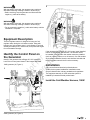
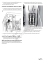
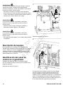
Identify the Control Panel on
the Generator
Identify if the generator has aBriggs GC-1031 controller.
Look for the control panel shown in the images that follow.
12kW generator (A, Figure 1).
1
20kW generator (A, Figure 2).
2
If the generator has aBriggs GC-1031 control panel installed,
look for a cold weather wire harness. The harness would
be installed if the generator has another accessory installed
(such as a battery warmer or an oil warmer). If a cold weather
wire harness is installed, then the wire harness included with
the fuel regulator warmer kit will not be necessary.
Installation
Only current licensed electrical professionalsare
qualified to dosystem installations. Installations must
obeyallrelatedcodes, industry standards and regulations.
The equipment warranty is VOID unless the system is
installed by licensed electricalprofessionals.
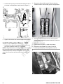
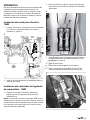
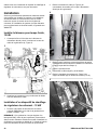
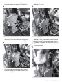
Install the Cold Weather Harness, 12kW
3
Not for
Reproduction

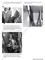
1. Connect the 3-pin plug on the warmer harness into the 3-
pin socket on the generator’s relay board (A, Figure 3).
3
2. Organize the excess wire harness lengths with cable ties.
Install Fuel Regulator Warmer - 12kW
1. Push the Prime Mover Disconnect (PMD) Switch on the
side of the generator to the “OFF” (0) position.
NOTE:If the generator does not have a PMD Switch, remove
the roof(as described in the Access Panels section of the
Installation/Operation manual)to access the 15 Amp fuse
at top of the control box and remove the fuse from the fuse
holder.
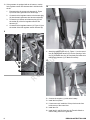
2. Remove the N1 and N2 fuses (A, Figure 4) from the
Transfer Switch to remove utility power to the generator.
4
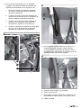
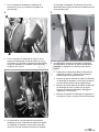
3. Remove the roofas described in the Access Panels
section of the Installation/Operation manual(if it was not
removed in step 1).
4. Remove the front panel.
5. Disconnect the negative (-) cable at the battery.
6. Remove the fuel regulator(A, Figure 5) from the
mounting bracket(B) by removing bolts (C and D).
5
4 BRIGGSandSTRATTON.COM
Not for
Reproduction

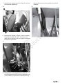
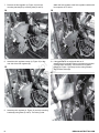
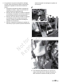
7. Attach the fuel regulator warmer (A, Figure 6) to the rear
side of the fuel regulator (B).
6
8. Attach the fuel regulator (A, Figure 7) onto the mounting
bracket(B) using bolts (C and D). The bolts (C) that
attach the fuel regulator to the fuel regulator bracket must
be torqued to 40-70 in-lbs.
7
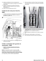
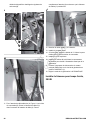
9. If the generator is not equipped with an oil warmer,
thefuel regulator warmer wire harnessincluded in the kit
is not necessary. Connect the fuel regulator warmer (A,
Figure 8) directly into the main generator wire harness
socket (B).
8
5
Not for
Reproduction

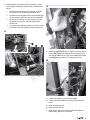
10. If the generator is equipped with an oil warmer, use the
fuel regulator warmer wire harness that is included with
the kit.
1. Disconnect the oil warmer wire harness(C, Figure
9) from the main generator wire harness (B).
2. Connect thefuel regulator warmer wire harnessplug
(A) intothemain generator wire harnesssocket (B).
3. Connect the oil warmer wire harness plug (C) into
the socket (D) of the fuel regulator warmer wire
harness (A).
4. Connect the fuel regulator warmer (A, Figure 10) into
the socket of the fuel regulator warmer harness (B).
9
10
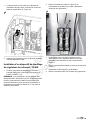
11. Attach the adhesive wire clip(A, Figure 11)to the control
box (B). Put the wire harness (C) into the opening of wire
clip (A). Close the wire clip (A) completely and make sure
that the wire harness (C) is attached correctly.
11
12. Connect the negative (-) cable at the battery.
13. Install the front panel.
14. If it was removed, install the 15 Amp fuse into the fuse
holder at top of the control box.
15. Install the roof.
16. Install the N1 and N2 fuses into the Transfer Switch to
restore utility power to the generator.
6 BRIGGSandSTRATTON.COM
Not for
Reproduction

17. Push the Prime Mover Disconnect (PMD) Switchon the
side of the generator to the “ON” (I) position.
18. Set the generator mode to AUTO.
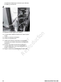
Install the Cold Weather Harness, 20kW
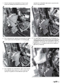
1. Connect the 3-pin plug on the warmer harness into the 3-
pin socket on the generator’s relay board (A, Figure 12).
12
2. Organize the excess wire harness lengths with cable ties.
Install Fuel Regulator Warmer - 20kW
1. Push the Prime Mover Disconnect (PMD) Switch on the
back of the generator to the “OFF” (0) position.
NOTE:If the generator does not have a PMD Switch, unlock
and openthe roof and remove the battery panel (as described
in the Access Panels section of the Installation/Operation
manual)to accessthe 15 Amp fuseand remove the fuse from
the fuse holder.
2. Remove the N1 and N2 fuses (A, Figure 13) from the
Transfer Switch toremove utility power to the generator.
13
3. Unlock and open the roof as described in the Access
Panels section of the Installation/Operation manual (if it
was not completed in step 1).
4. Remove the battery panel (if not removed in step 1).
5. Disconnect the negative (-) cable at the battery.
6. Remove the generator enclosure's back panel.
7
Not for
Reproduction

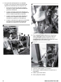
7. Remove the fuel regulator(A, Figure 14) from the
mounting bracket(B) by removing bolts (C and D).
14
8. Attach the fuel regulator warmer (A, Figure 15) to the
rear side of the fuel regulator (B).
15
9. Attach the fuel regulator (A, Figure 16) onto the mounting
bracket (B) using bolts (C and D).The bolts (C) that
attach the fuel regulator to the fuel regulator bracket must
be torqued to 40-70 in-lbs.
16
10. If the generator is not equipped with an oil
warmer,thefuel regulator warmer wire harnessincluded
in the kit is not necessary. Connect the fuel regulator
warmer(A, Figure 17) directly into the main generator
wire harness socket (B).
17
8 BRIGGSandSTRATTON.COM
Not for
Reproduction

11. If the generator is equipped with an oil warmer, use the
fuel regulator warmer wire harness that is included with
the kit.
1. Disconnect the oil warmer wire harness(C, Figure
18) from the main generator wire harness (B).
2. Connect thefuel regulator warmer wire harnessplug
(A) intothemain generator wire harnesssocket (B).
3. Connect the oil warmer wire harness plug (C) into
the socket (D) of the fuel regulator warmer wire
harness (A).
4. Connect the fuel regulator warmer (A, Figure 19) into
the socket of the fuel regulator warmer harness (B).
18
19
12. Attach the adhesive wire clip(A, Figure 20)to the vertical
support (B). Put the wire harness (C) into the opening of
wire clip (A). Close the wire clip (A) completely and make
sure that the wire harness (C) is attached correctly.
20
13. Connect the negative (-) cable at the battery.
14. If it was removed, install the 15 Amp fuse into the fuse
holder.
15. Install the battery panel.
16. Close and lock the roof.
17. Install the N1 and N2 fuses into the Transfer Switchto
restore utility power to the generator.
9
Not for
Reproduction


Instrucciones de seguridad
importantes
GUARDE ESTAS INSTRUCCIONES:este manual
contiene instrucciones importantes que deben ser leídas,
comprendidas y obedecidas durante la instalación de los kits
del generador y/o de los accesorios.
Símbolos de seguridad y
significados
Símbolo Significado
El símbolo de alerta de seguridad muestra un posible peligro
para su integridad física.
Lea el manual. El incumplimiento de las advertencias, las
instrucciones, el manual de instalación y el manual del
operador podría causar la muerte o lesiones graves.
Explosión
Descarga eléctrica
Arranque automático
Símbolo de alerta de seguridad
y palabras de señalización
El símbolo de alerta de seguridad identifica
información de seguridad sobre peligros que podrían
provocar lesiones personales. Se usa una palabra de
señalización (PELIGRO, ADVERTENCIA, o PRECAUCIÓN)
para indicar la probabilidad y la gravedad potencial de
las lesiones. Además, se usa un símbolo de peligro para
representar el tipo de riesgo.
PELIGRO indica un riesgo que, si no se evita, ocasionará la
muerte o lesiones graves.
ADVERTENCIA indica un riesgo que, si no se evita, podría
ocasionar la muerte o lesiones graves.
PRECAUCIÓN indica un riesgo que, si no se evita, podría
ocasionar lesiones menores o moderadas.
AVISO indica información que se considera importante pero
que no está relacionada con un peligro.
Mensajes de seguridad
ADVERTENCIA
No leer y no seguir las instrucciones de operación, todas
las advertencias y el manual del operador podría ocasionar
lesiones graves o la muerte.
ADVERTENCIA
Este producto contiene plomo y compuestos de plomo que,
de acuerdo con el estado de California, ocasionan defectos
de nacimiento u otros daños reproductivos. Lávese las
manos luego de manipular este producto. Cáncer y daño
reproductivo: www.P65Warnings.ca.gov.
ADVERTENCIA
El voltaje del generador y de la red pública podría provocar
una descarga eléctrica o quemaduras, lo que podría
ocasionar la muerte o lesiones graves.
• La instalación debe realizarla un profesional calificado.
• Desconecte todas las fuentes de electricidad antes de
instalar o hacer mantenimiento al equipo.
• Conecte el sistema a tierra antes de aplicar energía.
ADVERTENCIA
Voltaje peligroso: la instalación de cables de voltaje bajo y
alto en el mismo conducto podría provocar una descarga
eléctrica o quemaduras, lo que podría ocasionar la muerte o
lesiones graves.
• No opere un cable de voltaje bajo y alto en el mismo
conducto a menos que la clasificación del aislamiento en
TODOS los cables sea de 600V. Consulte NFPA70 para
más información.
ADVERTENCIA
Una batería presenta un riesgo de alta corriente de
cortocircuito.
• Quítese el reloj, los anillos u otros objetos metálicos.
• Use herramientas con mangos aislados.
• Desconecte la fuente de carga antes de conectar o
desconectar las terminales de la batería.
• No coloque herramientas o partes metálicas encima de las
baterías.
• Desconecte el cable negativo (-) de la batería durante la
instalación y el mantenimiento.
11
Not for
Reproduction

ADVERTENCIA
Las baterías almacenadas emiten gas hidrógeno explosivo
durante las recargas. La chispa más pequeña podría
encender el hidrógeno y causar una explosión, lo que puede
provocar la muerte o lesiones graves.
• NO elimine una batería en el fuego. Recicle la batería.
• NO permita que se produzca ninguna llama abierta, chispa
o calor, ni encienda un cigarrillo mientras carga la batería o
durante varios minutos después de la carga.
ADVERTENCIA
Con la batería conectada, el generador puede girar y
arrancar sin aviso, lo que podría provocar la muerte o
lesiones graves.
• Antes de reparar el equipo, detenga el generador y
desconecte el cable negativo (-) de la batería.
ADVERTENCIA
Con la batería conectada, el generador puede girar y
arrancar sin aviso, lo que podría provocar la muerte o
lesiones graves.
• No conecte el cable negativo (-) en la batería hasta finalizar
la instalación.
Descripción del equipo
Este calentador para el regulador de combustible está
diseñado para mantenerlo caliente durante los fríos meses de
invierno. Además de mantener el regulador de combustible
caliente en climas fríos, puede ayudar a prolongar la vida
de la batería, reducir el desgaste y proteger el motor de los
daños causados por el clima frío.
Identificación del panel de
control en el generador
Identifique si el generador tiene un controlador Briggs
GC-1031. Busque el panel de control que se muestra en las
imágenes siguientes.
Generador de 12kW (A, Figura 1).
1
Generador de 20kW (A, Figura 2).
2
Si el generador tiene instalado un panel de control Briggs
GC-1031, busque un arnés de cables para clima frío. El
arnés se instalaría si el generador tuviese otro accesorio
instalado (como un calentador de baterías o un calentador de
aceite). Si está instalado un arnés de cables para clima frío,
entonces no será necesario el arnés de cables incluido en el
kit de calentamiento del regulador de combustible.
12 BRIGGSandSTRATTON.COM
Not for
Reproduction

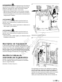
Instalación
Solo los profesionales eléctricos con licencia vigente están
calificados para hacer instalaciones de sistemas. Las
instalaciones deben obedecer todos los códigos, normas
y regulaciones de la industria. La garantía del equipo SE
INVALIDA a menos que el sistema se instale por parte de
profesionales eléctricos autorizados.
Instalación del arnés para clima frío,
12kW
1. Conecte el enchufe de 3clavijas del arnés del calentador
en el zócalo de 3clavijas del tablero de relés del
generador (A, Figura 3).
3
2. Organice el largo sobrante de los arneses de cable con
amarras para cables.
Instalación del calentador del regulador
de combustible - 12kW
1. Presione el interruptor Prime Mover Disconnect
(PMD) en el lado del generador hacia la posición
“APAGADO” (0).
NOTA:Si el generador no tiene un interruptor PMD, quite la
cubierta(como se describe en la sección Tableros de acceso
del manual de Instalación/Operación) para acceder al fusible
de 15 amperios en la parte superior de la caja de control y
retirar el fusible del portafusibles.
2. Retire los fusibles N1 y N2 (A, Figura 4) del interruptor
de transferencia para retirar la energía de la red pública
al generador.
4
3. Retire la cubierta como se describe la sección Tableros
de acceso del manual de Instalación/Operación (si no
fue retirada en el paso 1).
4. Retire el panel frontal.
5. Desconecte el cable negativo (-) de la batería.
6. Retire el regulador de combustible(A, Figura 5) del
soporte de montaje(B) retirando los pernos (C y D).
5
13
Not for
Reproduction

7. Fije el calentador del regulador de combustible (A, Figura
6) a la parte trasera del regulador de combustible (B).
6
8. Fije el regulador de combustible (A, Figura 7) en el
soporte de montaje(B) usando los pernos (C y D). Los
pernos (C) que fijan el regulador de combustible al
soporte del regulador de combustible deben tener un par
de torsión de 40-70 pulgadas-libras.
7
9. Si el generador no está equipado con un calentador de
aceite, el arnés de cables del calentador del regulador
de combustible incluido en el kit no es necesario.
Conecte el calentador del regulador de combustible (A,
Figura 8)
directamente en el receptáculo del arnés de cables del
generador principal (B).
8
14 BRIGGSandSTRATTON.COM
Not for
Reproduction

10. Si el generador está equipado con un calentador
de aceite, use el arnés de cables del calentador del
regulador de combustible que se incluye en el kit.
1. Desconecte el arnés de cables del calentador
de aceite(C, Figura 9)del arnés de cables del
generador principal (B).
2. Conecte el enchufe del arnés del calentador del
regulador de combustible (A) en el receptáculo del
arnés de cables del generador principal (B).
3. Conecte el enchufe del arnés del calentador de
aceite (C) en el receptáculo (D) del arnés del
calentador del regulador de combustible (A).
4. Conecte el calentador del regulador de combustible
(A, Figura 10) en el receptáculo del arnés del
calentador del regulador de combustible (B).
9
1
0
11. Fije el sujetador de cables adhesivo (A, Figura 11)a
la caja de control (B). Coloque el arnés de cables
(C) en la abertura del sujetador de cables (A). Cierre
completamente el sujeta cables (A) y asegúrese de que
el arnés de cables (C) esté bien sujetado.
1
1
12. Conecte el cable negativo (-) a la batería.
13. Instale el panel frontal.
14. Si fue retirado, instale el fusible de 15amperios en el
portafusibles de la parte superior de la caja de control.
15. Instale la cubierta.
15
Not for
Reproduction

16. Instale los fusibles N1 y N2 en el Interruptor de
Transferencia para restaurar la energía de la red pública
al generador.
17. Presione el interruptor Prime Mover Disconnect
(PMD) en el lado del generador hacia la posición
“ENCENDIDO” (I).
18. Ajuste el modo del generador a AUTO.
Instalación del arnés para clima frío,
20kW
1. Conecte el enchufe de 3clavijas del arnés del calentador
en el zócalo de 3clavijas del tablero de relés del
generador (A, Figura 12).
1
2
2. Organice el largo sobrante de los arneses de cable con
amarras para cables.
Instalar el calentador del regulador de
combustible - 20kW
1. Presione el interruptor Prime Mover Disconnect
(PMD) en el lado del generador hacia la posición
“APAGADO” (0).
NOTA:Si el generador no tiene un interruptor PMD,
desasegure y abra la cubierta y remueva el tablero de la
batería (como se describe en la sección Tableros de acceso
del manual de Instalación/Operación) para acceder al fusible
de 15 amperios y retirar el fusible del portafusibles.
2. Retire los fusibles N1 y N2 (A, Figura 13) del interruptor
de transferencia para retirar la energía de la red pública
al generador.
1
3
3. Desasegure y abra la cubierta como se describe en la
sección Tableros de acceso del manual de Instalación/
Operación (si no se completó en el paso 1).
4. Retire el tablero de la batería (si no se retiró en el paso
1).
5. Desconecte el cable negativo (-) de la batería.
6. Retiro del tablero trasero del recinto del generador.
16 BRIGGSandSTRATTON.COM
Not for
Reproduction

7. Retire el regulador de combustible(A, Figura 14) del
soporte de montaje(B) retirando los pernos (C y D).
1
4
8. Fije el calentador del regulador de combustible (A, Figura
15) a la parte trasera del regulador de combustible (B).
1
5
9. Fije el regulador de combustible (A, Figura 16) al soporte
de montaje (B) usando pernos (C y D).Los pernos (C)
que fijan el regulador de combustible al soporte del
regulador de combustible deben tener un par de torsión
de 40-70 pulgadas-libras.
1
6
10. Si el generador no está equipado con un calentador de
aceite, el arnés de cables del calentador del regulador de
combustible incluido en el kit no es necesario. Conecte
el calentador del regulador de combustible(A, Figura 17)
directamente en el receptáculo del arnés de cables del
generador principal (B).
1
7
17
Not for
Reproduction

11. Si el generador está equipado con un calentador
de aceite, use el arnés de cables del calentador del
regulador de combustible que se incluye en el kit.
1. Desconecte el arnés de cables del calentador
de aceite(C, Figura 18)del arnés de cables del
generador principal (B).
2. Conecte el enchufe del arnés del calentador del
regulador de combustible (A) en el receptáculo del
arnés de cables del generador principal (B).
3. Conecte el enchufe del arnés del calentador de
aceite (C) en el receptáculo (D) del arnés del
calentador del regulador de combustible (A).
4. Conecte el calentador del regulador de combustible
(A, Figura 19) en el receptáculo del arnés del
calentador del regulador de combustible (B).
1
8
1
9
12. Fije el sujetador de cables adhesivo(A, Figura 20)al
soporte vertical (B). Coloque el arnés de cables (C)
en la abertura del sujetador de cables (A). Cierre
completamente el sujeta cables (A) y asegúrese de que
el arnés de cables (C) esté bien sujeto.
2
0
13. Conecte el cable negativo (-) a la batería.
14. Si fue retirado, instale el fusible de 15amperios en el
portafusibles.
15. Instale el panel de la batería.
16. Cierre y bloquee la cubierta.
18 BRIGGSandSTRATTON.COM
Not for
Reproduction

17. Instale los fusibles N1 y N2 en el Interruptor de
Transferencia para restaurar la energía de la red pública
al generador.
18. Presione el interruptor Prime Mover Disconnect
(PMD) en el lado del generador hacia la posición
“ENCENDIDO” (I).
19. Ajuste el modo del generador a AUTO.
19
Not for
Reproduction

Consignes de sécurité
importantes
CONSERVEZ CES INSTRUCTIONS– Ce manuel renferme
d’importantes instructions à lire, à comprendre et à suivre
durant l’installation de la génératrice et/ou des accessoires.
Les symboles de sécurité et
leur signification
Symbole Signification
Le symbole d’alerte de sécurité indique un éventuel risque de
lésion corporelle.
Lire le manuel. Ne pas obéir aux avertissements, aux
instructions et aux manuels d’installation et de l’utilisateur peut
entraîner des blessures graves ou la mort.
Explosion
Décharge électrique
Démarrage automatique
Symbole d’alerte de sécurité et
mots-indicateurs
Le symbole d’alerte de sécurité identifie l’information
de sécurité relative aux dangers qui pourraient causer
des blessures. Un mot de signalisation (DANGER,
AVERTISSEMENT ou ATTENTION) est utilisé pour indiquer
la possibilité et la gravité des blessures potentielles. En plus,
un symbole de danger est utilisé pour représenter un type de
danger.
DANGER indique un danger qui, si non évité, provoquera la
mort ou des blessures graves.
AVERTISSEMENT indique un danger qui, si non évité,
pourrait causer la mort ou des blessures graves.
ATTENTION indique un danger qui, si non évité, pourrait
causer une blessure mineure ou modérée.
AVIS indique des informations considérées importantes,
mais non liées aux dangers.
Messages de sécurité
AVERTISSEMENT
L’omission de lire et de respecter le manuel d’utilisation,
tous les avertissements et toutes les instructions de
fonctionnement pourrait causer la mort ou des blessures
graves.
AVERTISSEMENT
Ce produit contient du plomb et des composés de plomb,
connus dans l’État de la Californie pour causer des
malformations congénitales ou les dommages à l’appareil
reproducteur. Nettoyez-vous les mains après la manipulation
de ce produit. Cancer et effets nocifs sur la reproduction–
www.P65Warnings.ca.gov.
AVERTISSEMENT
La tension de la génératrice et de l’électricité de service
pourrait causer un choc électrique ou des brûlures,
provoquant la mort ou des blessures graves.
• L’installation doit être effectuée par un technicien
professionnel.
• Déconnecter toutes les sources électriques avant d’installer
ou d’entretenir l’équipement.
• Mettre le système à la terre avant d’alimenter.
AVERTISSEMENT
Tension dangereuse– Installer un câble haute et basse
tension dans le même conduit pourrait causer un choc
électrique ou des brûlures, provoquant la mort ou des
blessures graves.
• Ne fixez pas les fils de basse et de haute tension dans le
même conduit, sauf si la valeur nominale de l’isolation de
TOUS les fils est de600V. Consulter NFPA70 pour plus
de renseignements.
AVERTISSEMENT
Une batterie présente un risque de courant fort lors d’un
court-circuit.
• Enlever vos montres, bagues et autres objets métalliques.
• Utiliser des outils dont les poignées sont isolées.
• Déconnecter la source de chargement avant de connecter
ou de déconnecter les bornes de la batterie.
• Ne pas placer d’outils ou de pièces métalliques sur les
batteries.
• Déconnecter le câble négatif (-) de la batterie lors
d’installation ou d’entretien.
20 BRIGGSandSTRATTON.COM
Not for
Reproduction
La page est en cours de chargement...
La page est en cours de chargement...
La page est en cours de chargement...
La page est en cours de chargement...
La page est en cours de chargement...
La page est en cours de chargement...
La page est en cours de chargement...
La page est en cours de chargement...
La page est en cours de chargement...
La page est en cours de chargement...
La page est en cours de chargement...
La page est en cours de chargement...
-
 1
1
-
 2
2
-
 3
3
-
 4
4
-
 5
5
-
 6
6
-
 7
7
-
 8
8
-
 9
9
-
 10
10
-
 11
11
-
 12
12
-
 13
13
-
 14
14
-
 15
15
-
 16
16
-
 17
17
-
 18
18
-
 19
19
-
 20
20
-
 21
21
-
 22
22
-
 23
23
-
 24
24
-
 25
25
-
 26
26
-
 27
27
-
 28
28
-
 29
29
-
 30
30
-
 31
31
-
 32
32


Simplicity 6845 Guide d'installation
- Taper
- Guide d'installation
- Ce manuel convient également à
dans d''autres langues
- English: Simplicity 6845 Installation guide
- español: Simplicity 6845 Guía de instalación