ESAB PakMaster™ 100 XL™ Plus Air Plasma Cutting Power Supply Manuel utilisateur
- Catégorie
- Système de soudage
- Taper
- Manuel utilisateur

Manual No. 0-2748
August 23, 1999
Operating Manual
A-02464
Air Plasma Cutting
Power Supply

WARNING
WARNING
Read and understand this entire Operating Manual and your
employer’s safety practices before installing, operating, or
servicing the equipment.
While the information contained in this Operating Manual
represents our best judgement, Thermal Dynamics Corporation
assumes no liability for its use.
Pak Master
®
100XL Plus Air Plasma Cutting Power Supply
Operating Manual Number 0-2748
Published by:
Thermal Dynamics Corporation
Industrial Park No. 2
West Lebanon, New Hampshire, USA 03784
(603) 298-5711
Copyright 1999 by
Thermal Dynamics Corporation
All rights reserved.
Reproduction of this work, in whole or in part, without written
permission of the publisher is prohibited.
The publisher does not assume and hereby disclaims any liability
to any party for any loss or damage caused by any error or
omission in the Pak Master
®
100XL Plus Air Plasma Cutting
Power Supply Operating Manual, whether such error results
from negligence, accident, or any other cause.
Printed in the United States of America
August 1999

Purchase Date
Power Supply
Torch
Record Serial Numbers For Warranty Purposes


TABLE OF CONTENTS
SECTION 1:
GENERAL INFORMATION .................................................................................................. 1
1.01 Notes, Cautions and Warnings ...................................................................... 1
1.02 Important Safety Precautions ........................................................................ 1
1.03 Publications ................................................................................................... 2
1.04 Note, Attention et Avertissement ................................................................... 3
1.05 Precautions De Securite Importantes ............................................................ 3
1.06 Documents De Reference ............................................................................. 5
1.07 Declaration of Conformity .............................................................................. 7
1.08 Statement of Warranty ................................................................................... 8
SECTION 2:
INTRODUCTION ................................................................................................................. 9
2.01 Scope of Manual............................................................................................ 9
2.02 General Description of System ...................................................................... 9
2.03 Specifications/Design Features ..................................................................... 9
2.04 Power Supply Options and Accessories ...................................................... 10
SECTION 3:
INSTALLATION PROCEDURES ........................................................................................ 11
3.01 Introduction.................................................................................................. 11
3.02 Site Selection............................................................................................... 11
3.03 Unpacking ................................................................................................... 11
3.04 Lifting Options.............................................................................................. 11
3.05 Input Power Connections............................................................................. 12
3.06 Input Voltage Selection ................................................................................ 12
3.07 Primary Input Power Cable Connections ..................................................... 13
3.08 Gas Connections......................................................................................... 14
3.09 Connecting Torch Leads .............................................................................. 16
3.10 Work Cable And Ground Connections ......................................................... 17
3.11 Tip Saver/Drag Cut Sensing Circuit ............................................................. 18
SECTION 4:
OPERATION ...................................................................................................................... 19
4.01 Introduction.................................................................................................. 19
4.02 Functional Overview .................................................................................... 19
4.03 Operating Controls ...................................................................................... 19
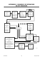
4.04 Sequence Of Operation ............................................................................... 21
4.05 Preparations for Operating........................................................................... 22
4.06 Cut Quality................................................................................................... 23
SECTION 5:
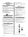
CUSTOMER/OPERATOR SERVICE.................................................................................. 25
5.01 Introduction.................................................................................................. 25
5.02 General Maintenance .................................................................................. 25
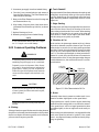
5.03 Common Operating Problems ..................................................................... 26
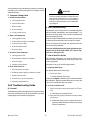
5.04 Troubleshooting Guide ................................................................................. 27
5.05 Power Supply Parts Replacement ............................................................... 29

TABLE OF CONTENTS (continued)
SECTION 6:
PARTS LISTS.....................................................................................................................31
6.01 Introduction.................................................................................................. 31
6.02 Ordering Information.................................................................................... 31
6.03 Complete Power Supply Replacement......................................................... 32
6.04 Replacement Parts ...................................................................................... 32
6.05 Options and Accessories............................................................................. 32
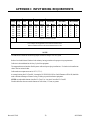
APPENDIX I: INPUT WIRING REQUIREMENTS ...................................................................... 33
APPENDIX II: SEQUENCE OF OPERATION (BLOCK DIAGRAM) ........................................... 34
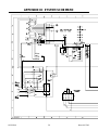
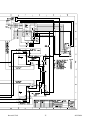
APPENDIX III: SYSTEM SCHEMATIC....................................................................................... 36

Date: 6/22/99 1 GENERAL INFORMATION
SECTION 1:
GENERAL INFORMATION
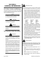
1.01 Notes, Cautions and Warnings
Throughout this manual, notes, cautions, and warnings
are used to highlight important information. These high-
lights are categorized as follows:
NOTE
An operation, procedure, or background informa-
tion which requires additional emphasis or is help-
ful in efficient operation of the system.
CAUTION
A procedure which, if not properly followed, may
cause damage to the equipment.
WARNING
A procedure which, if not properly followed, may
cause injury to the operator or others in the oper-
ating area.
1.02 Important Safety Precautions
WARNINGS
OPERATION AND MAINTENANCE OF
PLASMA ARC EQUIPMENT CAN BE DAN-
GEROUS AND HAZARDOUS TO YOUR
HEALTH.
Plasma arc cutting produces intense electric and
magnetic emissions that may interfere with the
proper function of cardiac pacemakers, hearing
aids, or other electronic health equipment. Per-
sons who work near plasma arc cutting applica-
tions should consult their medical health profes-
sional and the manufacturer of the health
equipment to determine whether a hazard exists.
To prevent possible injury, read, understand and
follow all warnings, safety precautions and in-
structions before using the equipment. Call 1-603-
298-5711 or your local distributor if you have any
questions.
GASES AND FUMES
Gases and fumes produced during the plasma cutting
process can be dangerous and hazardous to your health.
• Keep all fumes and gases from the breathing area.
Keep your head out of the welding fume plume.
• Use an air-supplied respirator if ventilation is not
adequate to remove all fumes and gases.
• The kinds of fumes and gases from the plasma arc
depend on the kind of metal being used, coatings
on the metal, and the different processes. You must
be very careful when cutting or welding any met-
als which may contain one or more of the follow-
ing:
Antimony Chromium Mercury
Arsenic Cobalt Nickel
Barium Copper Selenium
Beryllium Lead Silver
Cadmium Manganese Vanadium
• Always read the Material Safety Data Sheets (MSDS)
that should be supplied with the material you are
using. These MSDSs will give you the information
regarding the kind and amount of fumes and gases
that may be dangerous to your health.
• For information on how to test for fumes and gases
in your workplace, refer to item 1 in Subsection
1.03, Publications in this manual.
• Use special equipment, such as water or down draft
cutting tables, to capture fumes and gases.
• Do not use the plasma torch in an area where com-
bustible or explosive gases or materials are located.
• Phosgene, a toxic gas, is generated from the vapors
of chlorinated solvents and cleansers. Remove all
sources of these vapors.
ELECTRIC SHOCK
Electric Shock can injure or kill. The plasma arc process
uses and produces high voltage electrical energy. This
electric energy can cause severe or fatal shock to the op-
erator or others in the workplace.
• Never touch any parts that are electrically “live” or
“hot.”
• Wear dry gloves and clothing. Insulate yourself from
the work piece or other parts of the welding cir-
cuit.
• Repair or replace all worn or damaged parts.
• Extra care must be taken when the workplace is
moist or damp.

GENERAL INFORMATION 2 Date 6/22/99
• Install and maintain equipment according to NEC
code, refer to item 9 in Subsection 1.03, Publica-
tions.
• Disconnect power source before performing any ser-
vice or repairs.
• Read and follow all the instructions in the Operat-
ing Manual.
FIRE AND EXPLOSION
Fire and explosion can be caused by hot slag, sparks, or
the plasma arc.
• Be sure there is no combustible or flammable mate-
rial in the workplace. Any material that cannot be
removed must be protected.
• Ventilate all flammable or explosive vapors from
the workplace.
• Do not cut or weld on containers that may have held
combustibles.
• Provide a fire watch when working in an area where
fire hazards may exist.
• Hydrogen gas may be formed and trapped under
aluminum workpieces when they are cut under-
water or while using a water table. DO NOT cut
aluminum alloys underwater or on a water table
unless the hydrogen gas can be eliminated or dis-
sipated. Trapped hydrogen gas that is ignited will
cause an explosion.
NOISE
Noise can cause permanent hearing loss. Plasma arc pro-
cesses can cause noise levels to exceed safe limits. You
must protect your ears from loud noise to prevent per-
manent loss of hearing.
• To protect your hearing from loud noise, wear pro-
tective ear plugs and/or ear muffs. Protect others
in the workplace.
• Noise levels should be measured to be sure the deci-
bels (sound) do not exceed safe levels.
• For information on how to test for noise, see item 1
in Subsection 1.03, Publications, in this manual.
PLASMA ARC RAYS
Plasma Arc Rays can injure your eyes and burn your skin.
The plasma arc process produces very bright ultra violet
and infra red light. These arc rays will damage your
eyes and burn your skin if you are not properly protected.
• To protect your eyes, always wear a welding hel-
met or shield. Also always wear safety glasses with
side shields, goggles or other protective eye wear.
• Wear welding gloves and suitable clothing to pro-
tect your skin from the arc rays and sparks.
• Keep helmet and safety glasses in good condition.
Replace lenses when cracked, chipped or dirty.
• Protect others in the work area from the arc rays.
Use protective booths, screens or shields.
• Use the shade of lens as suggested in the following
per ANSI/ASC Z49.1:
Minimum Protective Suggested
Arc Current Shade No. Shade No.
Less Than 300* 8 9
300 - 400* 9 12
400 - 800* 10 14
* These values apply where the actual arc is clearly
seen. Experience has shown that lighter filters
may be used when the arc is hidden by the work-
piece.
1.03 Publications
Refer to the following standards or their latest revisions
for more information:
1. OSHA, SAFETY AND HEALTH STANDARDS,
29CFR 1910, obtainable from the Superintendent of
Documents, U.S. Government Printing Office, Wash-
ington, D.C. 20402
2. ANSI Standard Z49.1, SAFETY IN WELDING AND
CUTTING, obtainable from the American Welding
Society, 550 N.W. LeJeune Rd, Miami, FL 33126
3. NIOSH, SAFETY AND HEALTH IN ARC WELD-
ING AND GAS WELDING AND CUTTING, obtain-
able from the Superintendent of Documents, U.S.
Government Printing Office, Washington, D.C. 20402
4. ANSI Standard Z87.1, SAFE PRACTICES FOR OC-
CUPATION AND EDUCATIONAL EYE AND FACE
PROTECTION, obtainable from American National
Standards Institute, 1430 Broadway, New York, NY
10018
5. ANSI Standard Z41.1, STANDARD FOR MEN’S
SAFETY-TOE FOOTWEAR, obtainable from the
American National Standards Institute, 1430 Broad-
way, New York, NY 10018
6. ANSI Standard Z49.2, FIRE PREVENTION IN THE
USE OF CUTTING AND WELDING PROCESSES,
obtainable from American National Standards Insti-
tute, 1430 Broadway, New York, NY 10018
7. AWS Standard A6.0, WELDING AND CUTTING
CONTAINERS WHICH HAVE HELD COMBUS-
TIBLES, obtainable from American Welding Society,
550 N.W. LeJeune Rd, Miami, FL 33126

Date: 6/22/99 3 GENERAL INFORMATION
8. NFPA Standard 51, OXYGEN-FUEL GAS SYSTEMS
FOR WELDING, CUTTING AND ALLIED PRO-
CESSES, obtainable from the National Fire Protection
Association, Batterymarch Park, Quincy, MA 02269
9. NFPA Standard 70, NATIONAL ELECTRICAL CODE,
obtainable from the National Fire Protection Asso-
ciation, Batterymarch Park, Quincy, MA 02269
10. NFPA Standard 51B, CUTTING AND WELDING
PROCESSES, obtainable from the National Fire Pro-
tection Association, Batterymarch Park, Quincy, MA
02269
11. CGA Pamphlet P-1, SAFE HANDLING OF COM-
PRESSED GASES IN CYLINDERS, obtainable from
the Compressed Gas Association, 1235 Jefferson
Davis Highway, Suite 501, Arlington, VA 22202
12. CSA Standard W117.2, CODE FOR SAFETY IN
WELDING AND CUTTING, obtainable from the Ca-
nadian Standards Association, Standards Sales, 178
Rexdale Boulevard, Rexdale, Ontario, Canada M9W
1R3
13. NWSA booklet, WELDING SAFETY BIBLIOGRA-
PHY obtainable from the National Welding Supply
Association, 1900 Arch Street, Philadelphia, PA 19103
14. American Welding Society Standard AWSF4.1, REC-
OMMENDED SAFE PRACTICES FOR THE PREPA-
RATION FOR WELDING AND CUTTING OF CON-
TAINERS AND PIPING THAT HAVE HELD
HAZARDOUS SUBSTANCES, obtainable from the
American Welding Society, 550 N.W. LeJeune Rd,
Miami, FL 33126
15. ANSI Standard Z88.2, PRACTICE FOR RESPIRA-
TORY PROTECTION, obtainable from American
National Standards Institute, 1430 Broadway, New
York, NY 10018
1.04 Note, Attention et
Avertissement
Dans ce manuel, les mots “note,” “attention,” et
“avertissement” sont utilisés pour mettre en relief des
informations à caractère important. Ces mises en relief
sont classifiées comme suit :
NOTE
Toute opération, procédure ou renseignement
général sur lequel il importe d’insister davantage
ou qui contribue à l’efficacité de fonctionnement
du système.
ATTENTION
Toute procédure pouvant résulter
l’endommagement du matériel en cas de non-
respect de la procédure en question.
AVERTISSEMENT
Toute procédure pouvant provoquer des blessures
de l’opérateur ou des autres personnes se trouvant
dans la zone de travail en cas de non-respect de la
procédure en question.
1.05 Precautions De Securite
Importantes
AVERTISSEMENTS
L’OPÉRATION ET LA MAINTENANCE DU
MATÉRIEL DE SOUDAGE À L’ARC AU JET
DE PLASMA PEUVENT PRÉSENTER DES
RISQUES ET DES DANGERS DE SANTÉ.
Coupant à l’arc au jet de plasma produit de l’énergie
électrique haute tension et des émissions
magnétique qui peuvent interférer la fonction
propre d’un “pacemaker” cardiaque, les appareils
auditif, ou autre matériel de santé electronique.
Ceux qui travail près d’une application à l’arc au
jet de plasma devrait consulter leur membre
professionel de médication et le manufacturier de
matériel de santé pour déterminer s’il existe des
risques de santé.
Il faut communiquer aux opérateurs et au person-
nel TOUS les dangers possibles. Afin d’éviter les
blessures possibles, lisez, comprenez et suivez tous
les avertissements, toutes les précautions de sécurité
et toutes les consignes avant d’utiliser le matériel.
Composez le + 603-298-5711 ou votre distributeur
local si vous avez des questions.
FUMÉE et GAZ
La fumée et les gaz produits par le procédé de jet de
plasma peuvent présenter des risques et des dangers de
santé.
• Eloignez toute fumée et gaz de votre zone de respi-
ration. Gardez votre tête hors de la plume de fumée
provenant du chalumeau.
• Utilisez un appareil respiratoire à alimentation en
air si l’aération fournie ne permet pas d’éliminer la
fumée et les gaz.

GENERAL INFORMATION 4 Date 6/22/99
• Les sortes de gaz et de fumée provenant de l’arc de
plasma dépendent du genre de métal utilisé, des
revêtements se trouvant sur le métal et des différents
procédés. Vous devez prendre soin lorsque vous
coupez ou soudez tout métal pouvant contenir un
ou plusieurs des éléments suivants:
antimoine cadmium mercure
argent chrome nickel
arsenic cobalt plomb
baryum cuivre sélénium
béryllium manganèse vanadium
• Lisez toujours les fiches de données sur la sécurité
des matières (sigle américain “MSDS”); celles-ci
devraient être fournies avec le matériel que vous
utilisez. Les MSDS contiennent des renseignements
quant à la quantité et la nature de la fumée et des
gaz pouvant poser des dangers de santé.
• Pour des informations sur la manière de tester la
fumée et les gaz de votre lieu de travail, consultez
l’article 1 et les documents cités à la page 5.
• Utilisez un équipement spécial tel que des tables de
coupe à débit d’eau ou à courant descendant pour
capter la fumée et les gaz.
• N’utilisez pas le chalumeau au jet de plasma dans
une zone où se trouvent des matières ou des gaz
combustibles ou explosifs.
• Le phosgène, un gaz toxique, est généré par la fumée
provenant des solvants et des produits de nettoyage
chlorés. Eliminez toute source de telle fumée.
CHOC ELECTRIQUE
Les chocs électriques peuvent blesser ou même tuer. Le
procédé au jet de plasma requiert et produit de l’énergie
électrique haute tension. Cette énergie électrique peut
produire des chocs graves, voire mortels, pour l’opérateur
et les autres personnes sur le lieu de travail.
• Ne touchez jamais une pièce “sous tension” ou
“vive”; portez des gants et des vêtements secs.
Isolez-vous de la pièce de travail ou des autres par-
ties du circuit de soudage.
• Réparez ou remplacez toute pièce usée ou
endommagée.
• Prenez des soins particuliers lorsque la zone de tra-
vail est humide ou moite.
• Montez et maintenez le matériel conformément au
Code électrique national des Etats-Unis. (Voir la
page 5, article 9.)
• Débranchez l’alimentation électrique avant tout tra-
vail d’entretien ou de réparation.
• Lisez et respectez toutes les consignes du Manuel
de consignes.
INCENDIE ET EXPLOSION
Les incendies et les explosions peuvent résulter des scories
chaudes, des étincelles ou de l’arc de plasma. Le procédé
à l’arc de plasma produit du métal, des étincelles, des
scories chaudes pouvant mettre le feu aux matières com-
bustibles ou provoquer l’explosion de fumées
inflammables.
• Soyez certain qu’aucune matière combustible ou in-
flammable ne se trouve sur le lieu de travail.
Protégez toute telle matière qu’il est impossible de
retirer de la zone de travail.
• Procurez une bonne aération de toutes les fumées
inflammables ou explosives.
• Ne coupez pas et ne soudez pas les conteneurs ayant
pu renfermer des matières combustibles.
• Prévoyez une veille d’incendie lors de tout travail
dans une zone présentant des dangers d’incendie.
• Le gas hydrogène peut se former ou s’accumuler
sous les pièces de travail en aluminium lorsqu’elles
sont coupées sous l’eau ou sur une table d’eau. NE
PAS couper les alliages en aluminium sous l’eau ou
sur une table d’eau à moins que le gas hydrogène
peut s’échapper ou se dissiper. Le gas hydrogène
accumulé explosera si enflammé.
RAYONS D’ARC DE PLASMA
Les rayons provenant de l’arc de plasma peuvent blesser
vos yeux et brûler votre peau. Le procédé à l’arc de plasma
produit une lumière infra-rouge et des rayons ultra-vio-
lets très forts. Ces rayons d’arc nuiront à vos yeux et
brûleront votre peau si vous ne vous protégez pas
correctement.
• Pour protéger vos yeux, portez toujours un casque
ou un écran de soudeur. Portez toujours des lunettes
de sécurité munies de parois latérales ou des lu-
nettes de protection ou une autre sorte de protec-
tion oculaire.
• Portez des gants de soudeur et un vêtement
protecteur approprié pour protéger votre peau
contre les étincelles et les rayons de l’arc.
• Maintenez votre casque et vos lunettes de protec-
tion en bon état. Remplacez toute lentille sale ou
comportant fissure ou rognure.
• Protégez les autres personnes se trouvant sur la zone
de travail contre les rayons de l’arc en fournissant
des cabines ou des écrans de protection.

Date: 6/22/99 5 GENERAL INFORMATION
• Utilisez la nuance de lentille qui est suggèrée dans
le recommendation qui suivent ANSI/ASC Z49.1:
Nuance Minimum Nuance Suggerée
Courant Arc Protective Numéro Numéro
Moins de 300* 8 9
300 - 400* 9 12
400 - 800* 10 14
* Ces valeurs s’appliquent ou l’arc actuel est observé
clairement. L’experience a démontrer que les filtres
moins foncés peuvent être utilisés quand l’arc est
caché par moiceau de travail.
BRUIT
Le bruit peut provoquer une perte permanente de l’ouïe.
Les procédés de soudage à l’arc de plasma peuvent
provoquer des niveaux sonores supérieurs aux limites
normalement acceptables. Vous dú4ez vous protéger les
oreilles contre les bruits forts afin d’éviter une perte
permanente de l’ouïe.
• Pour protéger votre ouïe contre les bruits forts, portez
des tampons protecteurs et/ou des protections
auriculaires. Protégez également les autres
personnes se trouvant sur le lieu de travail.
• Il faut mesurer les niveaux sonores afin d’assurer
que les décibels (le bruit) ne dépassent pas les
niveaux sûrs.
• Pour des renseignements sur la manière de tester le
bruit, consultez l’article 1, page 5.
1.06 Documents De Reference
Consultez les normes suivantes ou les révisions les plus
récentes ayant été faites à celles-ci pour de plus amples
renseignements :
1. OSHA, NORMES DE SÉCURITÉ DU TRAVAIL ET
DE PROTECTION DE LA SANTÉ, 29CFR 1910,
disponible auprès du Superintendent of Docu-
ments, U.S. Government Printing Office, Washing-
ton, D.C. 20402
2. Norme ANSI Z49.1, LA SÉCURITÉ DES
OPÉRATIONS DE COUPE ET DE SOUDAGE,
disponible auprès de la Société Américaine de
Soudage (American Welding Society), 550 N.W.
LeJeune Rd., Miami, FL 33126
3. NIOSH, LA SÉCURITÉ ET LA SANTÉ LORS DES
OPÉRATIONS DE COUPE ET DE SOUDAGE À
L’ARC ET AU GAZ, disponible auprès du Superin-
tendent of Documents, U.S. Government Printing
Office, Washington, D.C. 20402
4. Norme ANSI Z87.1, PRATIQUES SURES POUR LA
PROTECTION DES YEUX ET DU VISAGE AU
TRAVAIL ET DANS LES ECOLES, disponible de
l’Institut Américain des Normes Nationales (Ameri-
can National Standards Institute), 1430 Broadway,
New York, NY 10018
5. Norme ANSI Z41.1, NORMES POUR LES
CHAUSSURES PROTECTRICES, disponible auprès
de l’American National Standards Institute, 1430
Broadway, New York, NY 10018
6. Norme ANSI Z49.2, PRÉVENTION DES
INCENDIES LORS DE L’EMPLOI DE PROCÉDÉS
DE COUPE ET DE SOUDAGE, disponible auprès
de l’American National Standards Institute, 1430
Broadway, New York, NY 10018
7. Norme A6.0 de l’Association Américaine du
Soudage (AWS), LE SOUDAGE ET LA COUPE DE
CONTENEURS AYANT RENFERMÉ DES
PRODUITS COMBUSTIBLES, disponible auprès de
la American Welding Society, 550 N.W. LeJeune Rd.,
Miami, FL 33126
8. Norme 51 de l’Association Américaine pour la Pro-
tection contre les Incendies (NFPA), LES SYSTEMES
À GAZ AVEC ALIMENTATION EN OXYGENE
POUR LE SOUDAGE, LA COUPE ET LES
PROCÉDÉS ASSOCIÉS, disponible auprès de la
National Fire Protection Association, Batterymarch
Park, Quincy, MA 02269
9. Norme 70 de la NFPA, CODE ELECTRIQUE NA-
TIONAL, disponible auprès de la National Fire Pro-
tection Association, Batterymarch Park, Quincy, MA
02269
10. Norme 51B de la NFPA, LES PROCÉDÉS DE
COUPE ET DE SOUDAGE, disponible auprès de
la National Fire Protection Association,
Batterymarch Park, Quincy, MA 02269
11. Brochure GCA P-1, LA MANIPULATION SANS
RISQUE DES GAZ COMPRIMÉS EN CYLINDRES,
disponible auprès de l’Association des Gaz
Comprimés (Compressed Gas Association), 1235
Jefferson Davis Highway, Suite 501, Arlington, VA
22202
12. Norme CSA W117.2, CODE DE SÉCURITÉ POUR
LE SOUDAGE ET LA COUPE, disponible auprès
de l’Association des Normes Canadiennes, Stan-
dards Sales, 178 Rexdale Boulevard, Rexdale,
Ontario, Canada, M9W 1R3
13. ivret NWSA, BIBLIOGRAPHIE SUR LA SÉCURITÉ
DU SOUDAGE, disponible auprès de l’Association
Nationale de Fournitures de Soudage (National
Welding Supply Association), 1900 Arch Street,
Philadelphia, PA 19103

GENERAL INFORMATION 6 Date 6/22/99
14. Norme AWSF4.1 de l’Association Américaine de
Soudage, RECOMMANDATIONS DE PRA-
TIQUES SURES POUR LA PRÉPARATION À LA
COUPE ET AU SOUDAGE DE CONTENEURS
ET TUYAUX AYANT RENFERMÉ DES
PRODUITS DANGEREUX , disponible auprès de
la American Welding Society, 550 N.W. LeJeune
Rd., Miami, FL 33126
15. Norme ANSI Z88.2, PRATIQUES DE PROTEC-
TION RESPIRATOIRE, disponible auprès de
l’American National Standards Institute, 1430
Broadway, New York, NY 10018

Date: 6/22/99 7 GENERAL INFORMATION
1.07 Declaration of Conformity
Manufacturer: Thermal Dynamics Corporation
Address: Industrial Park #2
West Lebanon, New Hampshire 03784
USA
The equipment described in this manual conforms to all applicable aspects and regulations of the ‘Low Voltage Direc-
tive’ (European Council Directive 73/23/EEC as amended by Council Directive 93/68/EEC) and to the National
legislation for the enforcement of this Directive.
Serial numbers are unique with each individual piece of equipment and details description, parts used to manufacture
a unit and date of manufacture.
National Standard and Technical Specifications
The product is designed and manufactured to a number of standards and technical requirements among them are:
* CSA (Canadian Standards Association) standard C22.2 number 60 for Arc welding equipment.
* UL (Underwriters Laboratory) rating 94VO flammability testing for all printed-circuit boards used.
* ISO/IEC 60974-1 (BS 638-PT10) (EN 60 974-1) (EN50192) (EN50078) applicable to plasma cutting equipment and associ-
ated accessories.
* Extensive product design verification is conducted at the manufacturing facility as part of the routine design and
manufacturing process. This is to ensure the product is safe, when used according to instructions in this manual and
related industry standards, and performs as specified. Rigorous testing is incorporated into the manufacturing
process to ensure the manufactured product meets or exceeds all design specifications.
Thermal Dynamics has been manufacturing products for more than 30 years, and will continue to achieve excellence in our
area of manufacture.
Manufacturers responsible representative: Steve Ward
Director of Operations
Thermadyne UK
Chorley England

GENERAL INFORMATION 8 Date 6/22/99
1.08 Statement of Warranty
LIMITED WARRANTY: Thermal Dynamics
®
Corporation (hereinafter “Thermal”) warrants that its products will be free of defects in
workmanship or material. Should any failure to conform to this warranty appear within the time period applicable to the Thermal
products as stated below, Thermal shall, upon notification thereof and substantiation that the product has been stored, installed, operated,
and maintained in accordance with Thermal’s specifications, instructions, recommendations and recognized standard industry practice,
and not subject to misuse, repair, neglect, alteration, or accident, correct such defects by suitable repair or replacement, at Thermal’s sole
option, of any components or parts of the product determined by Thermal to be defective.
THIS WARRANTY IS EXCLUSIVE AND IS IN LIEU OF ANY WARRANTY OF MERCHANTABILITY OR FITNESS FOR A
PARTICULAR PURPOSE.
LIMITATION OF LIABILITY: Thermal shall not under any circumstances be liable for special or consequential damages, such as, but
not limited to, damage or loss of purchased or replacement goods, or claims of customers of distributor (hereinafter “Purchaser”) for
service interruption. The remedies of the Purchaser set forth herein are exclusive and the liability of Thermal with respect to any
contract, or anything done in connection therewith such as the performance or breach thereof, or from the manufacture, sale, delivery,
resale, or use of any goods covered by or furnished by Thermal whether arising out of contract, negligence, strict tort, or under any
warranty, or otherwise, shall not, except as expressly provided herein, exceed the price of the goods upon which such liability is based.
THIS WARRANTY BECOMES INVALID IF REPLACEMENT PARTS OR ACCESSORIES ARE USED WHICH MAY IMPAIR THE
SAFETY OR PERFORMANCE OF ANY THERMAL PRODUCT.
THIS WARRANTY IS INVALID IF THE PRODUCT IS SOLD BY NON-AUTHORIZED PERSONS.
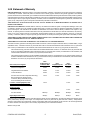
The limited warranty periods for Thermal products shall be as follows (with the exception of XL Plus Series, CutMaster 80XL , Cougar
and DRAG-GUN): A maximum of three (3) years from date of sale to an authorized distributor and a maximum of two (2) years from
date of sale by such distributor to the Purchaser, and with the further limitations on such two (2) year period (see chart below).
The limited warranty period for XL Plus Series and CutMaster 80XL shall be as follows: A maximum of four (4) years from date
of sale to an authorized distributor and a maximum of three (3) years from date of sale by such distributor to the Purchaser, and
with the further limitations on such three (3) year period (see chart below).
The limited warranty period for Cougar and DRAG-GUN shall be as follows: A maximum of two (2) years from date of sale to an
authorized distributor and a maximum of one (1) year from date of sale by such distributor to the Purchaser, and with the further
limitations on such two (2) year period (see chart below).
Parts
XL Plus Series & Parts Parts
PAK Units, Power Supplies CutMaster 80XL Cougar/Drag-Gun All Others Labor
Main Power Magnetics 3 Years 1 Year 2 Years 1 Year
Original Main Power Rectifier 3 Years 1 Year 2 Years 1 Year
Control PC Board 3 Years 1 Year 2 Years 1 Year
All Other Circuits And Components Including, 1 Year 1 Year 1 Year 1 Year
But Not Limited To, Starting Circuit,
Contactors, Relays, Solenoids, Pumps,
Power Switching Semi-Conductors
Consoles, Control Equipment, Heat 1 Year 1 Year 1 Year
Exchanges, And Accessory Equipment
Torch And Leads
Maximizer 300 Torch 1 Year 1 Year
All Other Torches 180 Days 180 Days 180 Days 180 Days
Repair/Replacement Parts 90 Days 90 Days 90 Days None
Warranty repairs or replacement claims under this limited warranty must be submitted by an authorized Thermal Dynamics® repair
facility within thirty (30) days of the repair. No transportation costs of any kind will be paid under this warranty. Transportation
charges to send products to an authorized warranty repair facility shall be the responsibility of the customer. All returned goods shall
be at the customer’s risk and expense. This warranty supersedes all previous Thermal warranties.
Effective May 6, 1999

Manual 0-2748 9 SECTION 2: INTRODUCTION
SECTION 2:
INTRODUCTION
2.01 Scope of Manual
This manual contains descriptions, operating instructions,
and basic maintenance procedures for the PAK Master
®
100XL PLUS Air Plasma Cutting Power Supply only. Ser-
vice of this equipment is restricted to Thermal Dynamics
trained personnel; unqualified personnel are strictly cau-
tioned against attempting repairs or adjustments not cov-
ered in this manual, at the risk of voiding the Warranty.
Read this manual thoroughly. A complete understand-
ing of the characteristics and capabilities of this equip-
ment will assure the dependable operation for which it
was designed.
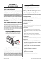
2.02 General Description of System
The 100XL PLUS System includes a power supply, PCH/
M-80 torch & leads and work cable & clamp.
The Power Supply provides 80 amp maximum output
and includes all control circuitry, electrical and gas in-
puts and outputs, pilot circuitry, torch leads receptacle
and a work cable with clamp.
NOTE
The power supply can be ordered in various con-
figurations with various options factory installed.
A-02462
Torch and Leads
Work Cable and Clamp
XL PLUS Power Supply
Figure 2-1 Pak Master 100XL Plus System
The PCH/M-80 torch provides a maximum 1 inch (25.4
mm) cut capacity. Hand torches are available in a 70°
and 90° configuration; a machine torch is available in a
180° configuration. Torch leads are available in 25 ft (7.6
m), or 50 ft (15.2 m) lengths with fittings for simple in-
stallation. Spare Parts Kits are available for the torches
which provide an assortment of replacement torch parts.
NOTES
For Torch information, refer to the PCH/M-80
manual 0-2753.
Refer to Section 2.04 in this manual for list of power
supply options and accessories.
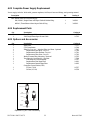
2.03 Specifications/Design Features
A. Power Supply Technical Specifications
The following specifications apply to the Power Supply
only:
1. Front Panel Controls
ON/OFF Switch, RUN/SET/LATCH Switch and
Output Current Control
2. Front Panel LED Indicators
AC, TEMP, GAS, DC
3. Rear Panel
Input Power Cable Strain Relief, Gas Connection, Gas
Regulator/Filter Assembly
4. Input Power
Can be configured for the following input power:
208/230/240 VAC (±10%), 50/60 Hz, Single or Three-
Phase
380/415 VAC (±10%), 50/60 Hz, Three-Phase
460 VAC (±10%), 50/60 Hz, Single or Three-Phase
5. Output Power
Continuously variable from 15 to 80 Amps maximum
6. Duty Cycle
40% Duty Cycle at an output of 112VDC/80 amps
100% Duty Cycle at an output of 112VDC/60 amps
7. Cut Capacity (Mild Steel)
1 inch (25.4 mm); 1-1/4 inch (31.8 mm) severance
8. Pilot Circuitry
Capacitive Discharge (CD), Pulsed DC
9. Weight
68 lbs ( 31 kg) w/work lead
75 lbs ( 34 kg) w/work lead, torch & lead

SECTION 2: INTRODUCTION 10 Manual 0-2748
10. Overall Dimensions
Overall dimensions are with handle, lead wrap
bracket, and Gas Regulator/Filter Assembly installed.
19" (482 mm) High x 13" (330 mm) Wide x 24.75" (630
mm) Long
B. Gas Regulator/Filter Assembly
Specifications
The following specifications apply to the Gas Regulator/
Filter Assembly only:
1. Gas regulator maximum gauge pressure
160 PSI (11 bar)
2. Maximum input gas pressure
125 PSI (8.6 bar)
3. Filter
Coalescent type filter
2.04 Power Supply Options and
Accessories
NOTE
Refer to Section 6, Parts Lists, for part numbers
and ordering information.
The following are accessories that are available for this
power supply:
A. Dry Air Filter Kit
An optional in-line filter for use on compressed air
shop systems. Filters moisture and particulate mat-
ter from the air stream to at least .85 microns.
B. Two Stage Air Line Filter
An alternative to the Dry Air Filter, this optional two
stage air line filter is for use on compressed air shop
systems. Filters moisture and particulate matter from
air stream to 5.0 microns. This filter assembly is pre-
assembled at the factory and need only be attached to
the power supply.
C. High Pressure Regulators
High pressure regulators are available for air and ni-
trogen. The regulators are used to set the proper pres-
sure for the type gas being used.
NOTE
Regulators should not be installed with options A
or B above.
D. Smart Cart
Steel cart on easy rolling 10" pneumatic tires to pro-
vide maximum mobility for the power supply. Handle
is 3/4" tubing with hooks for storage of torch leads.
A tie down strap is also included.
E. 575V Transformer
This step-down transformer allows the power sup-
ply to operate with 575 VAC three-phase input power.
F. Computer Control Cable (CNC)
NOTE
This accessory can be used only with the PCM-80
Torches.
The interface cable is available in two lengths, 25 ft
(7.6 m) and 50 ft (15.2 m). The cable is used to inter-
face the power supply with an auxiliary control de-
vice to provide OK-To-Move and ON/OFF signals.

Manual 0-2748 11 SECTION 3: INSTALLATION PROCEDURES
SECTION 3:
INSTALLATION
PROCEDURES
3.01 Introduction
NOTE
Depending on how the system was ordered, some
Power Supply options may already be installed.
If option(s) have been factory installed some of the
instructions may not apply. It is recommended
that all subsections be read for general informa-
tion.
This section describes installation of the Power Supply
and connecting the Torch.
These instructions apply to the Power Supply only; in-
stallation procedures for the Torch, Options, and Acces-
sories are given in Manuals specifically provided for those
units.
The complete installation consists of:
1. Site selection
2. Unpacking
3. Connections to Power Supply
a. Input Power
b. Gas
c. Work Cable
d. Torch Leads
4. Grounding
5. Operator training
3.02 Site Selection
Select a clean, dry location with good ventilation and ad-
equate working space around all components.
NOTE
Review Important Safety Precautions (page 1) to
be sure that the selected location meets all safety
requirements.
The power supply is fan cooled by air flow through the
front panel to the rear panel. Air flow must not be ob-
structed. Provide at least 2 feet (0.6 m) in the rear and at
least 6 inches (0.15 m) on each side for clearance . Pro-
vide sufficient clearance in front of the unit to allow ac-
cess to the front panel controls (minimum 6 inches or 0.15
m).
CAUTION
Operation without proper air flow will inhibit
proper cooling and reduce duty cycle.
3.03 Unpacking
Each component of the system is packaged and protected
with a carton and packing material to prevent damage
during shipping.
1. Unpack each item and remove all packing material.
NOTE
The Cutting Spare Parts Kit is shipped in the Torch
Leads Storage Area on the side of the Power Sup-
ply.
2. Locate the packing list(s) and use the list to identify
and account for each item.
3. Inspect each item for possible shipping damage. If
damage is evident, contact your distributor and/or
shipping company before proceeding with system in-
stallation.
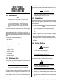
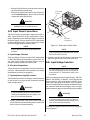
3.04 Lifting Options
WARNINGS
Do not touch live electrical parts.
Disconnect input power conductors from de-ener-
gized supply line before moving unit.
This unit is equipped with one handle mounted onto the
top of the enclosure for hand carrying purposes.
WARNING
FALLING EQUIPMENT can cause serious per-
sonal injury and equipment damage.
• Lift unit with the handle on top of the enclosure.
• Persons only of adequate physical strength should
lift the unit.
• Use hand cart or similar device of adequate capac-
ity.

SECTION 3: INSTALLATION PROCEDURES 12 Manual 0-2748
• If using a fork lift vehicle, place and secure unit on a
proper skid before transporting.
• This unit has a handle mounted on top of the enclo-
sure for hand lifting only. Be sure unit is lifted and
transported safely and securely.
WARNING
HANDLE is not for mechanical lifting.
3.05 Input Power Connections
The Power Supply accepts input voltages from 208V to
460V. Input can be 50 or 60 Hz, single-phase or three-
phase. Depending on how the Power Supply was ordered
the Power Supply is factory wired for 230V single-phase
or 460V three-phase input. For any other input voltage,
the Power Supply must be internally reset.
NOTE
Refer to Section 3.06, Input Voltage Selection for
procedure.
A. Input Voltage Selection
The Power Supply is factory-wired for 230V single-phase
or 460V three-phase input depending on the order. For
any other input voltage, the Power Supply must be
changed using the procedure in Section 3.06.
B. Electrical Connections
The power source must conform to local and national elec-
tric codes. Recommended circuit protection and wiring
requirements are shown in Appendix I.
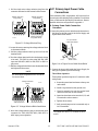
C. Opening Power Supply Enclosure
The left side panel of the Power Supply must be removed
to gain access to the input power connections and the
input voltage selection.
WARNING
Disconnect primary power at the source before as-
sembling or disassembling the Power Supply, torch
parts, or torch and leads assemblies.
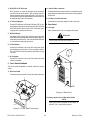
1. Using a phillips head screw driver remove the five
screws which secure the left side panel (viewed from
front of unit) to the frame assembly.
Left Side
Panel
Screws
(5 places)
A-02504
Figure 3-1 Removing Left Side Panel
NOTE
There is a ground wire connection to the Left Side
Panel on the inside of the unit.
2. Carefully pull the Left Side Panel up and away from
the unit to gain access to the inside of the unit.
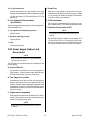
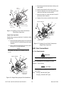
3.06 Input Voltage Selection
NOTE
For power supplies to use 575 VAC input power,
the unit must be setup for 460V three-phase op-
eration and the 575V Transformer Accessory must
be installed.
The Power Supply has three voltage settings; 208/230/
240VAC, 380/415VAC, or 460VAC. Power Supplies are
factory-wired for 230V single-phase or 460VAC three-
phase input depending on the order. Input voltage se-
lection is accomplished by switching an internal buss bar
and connector inside the Power Supply. Also, for single-
phase operation a jumper wire must be properly installed.
WARNING
Disconnect primary power at the source before as-
sembling or disassembling the power supply, torch
parts, or torch and leads assemblies.
To change the voltage selection use the following proce-
dure as required:

Manual 0-2748 13 SECTION 3: INSTALLATION PROCEDURES
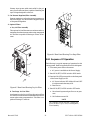
1. Pull the single wire voltage selection plug from the
connector mounted on the internal center chassis.
380-415V/460V
220V
460V
380-
415V
220V
380-
415V
460V
220V
380-415V/460V
220V
Voltage Selection
Plug (220V)
Voltage Selection
Plug (460V)
Voltage Selection
Plug (380-415V)
A-01361
Figure 3-2 Voltage Selection Plug
2. Loosen the screws securing the voltage selection block
to the terminal block.
3. Pull the voltage selection block up and out from the
terminal block.
4. Turn the voltage selection block to the desired voltage
to be used. Use 220V for units using 208/230/240V
input and 380-415V/460V for 380/415V or 460V in-
put power.
5. Slide the voltage selection block onto the terminal block
and tighten all the screws.
NOTE
All screws must be tightened even if not used on
the terminal block.
380-415V/460V
220V
460V
380-
415V
220V
208/230/240VAC
380-
415V
460V
220V
380-415V/460V
220V
380-415V/460VAC
Voltage Selection
Block
A-01347
Figure 3-3 Voltage Selection Block Installation
6. Move the voltage selection plug to the desired input
connector for 220V (208/230/240V), 380/415V, or
460V input power operation.
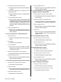
3.07 Primary Input Power Cable
Connections
Units ordered as 230V, single-phase, will have a six foot
power input cable and plug factory installed. For all other
units, a cable must be provided by the end user. Recom-
mended cable sizes are specified in Appendix I.
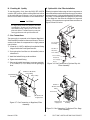
A. Primary Power Cable Connection
Procedure
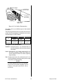
1. Route the primary power cable through the strain re-
lief fitting in the rear panel of the Power Supply and
tighten strain relief screws.
AC Input Power
Cable Strain Relief
AC Input
Power Cable
A-00912
Figure 3-4 AC Input Power Cable Strain Relief
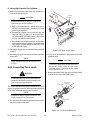
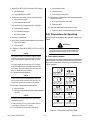
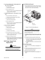
2. Connect the input cable inside the Power Supply for
the type of operation per the following:
Three-Phase Operation
Three-phase operation requires a 3-conductor cable
with ground.
a. Locate the ground stud and remove the top nut
and washer.
b. Install a lug terminal on the ground wire.
c. Place the ground wire onto the ground stud
and secure with the nut and washer.
d. Insert the other three wires into the L1, L2, and
L3 terminals on the contactor.
e. Tighten all set screws.
f. Verify unused jumper wire is connected only to
the L3 terminals.
NOTE
The jumper wire from L1 to L4 must not be re-
moved.

SECTION 3: INSTALLATION PROCEDURES 14 Manual 0-2748
L1
L2
L3
Input
Contactor
AC Input
Power Cable
GND
Unused Jumper
L3 to L3 (storage)
A-02670
Figure 3-5 Primary Power Cable Connections -
Three-Phase Operation
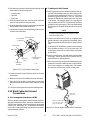
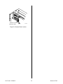
Single-Phase Operation
Single-phase operation requires a 2-conductor cable
with ground.
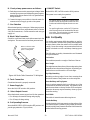
a. Locate the single-phase jumper wire connected
between the two L3 terminal lugs on the input
contactor.
b. Move one end of the jumper wire from termi-
nal lug L3 to L2 at the contactor.
NOTE
The jumper wire from L1 to L4 must not be re-
moved.
Single Phase
Jumper Wire
(L2 to L3)
Input Contactor
A-00914
L3
L2
Figure 3-6 Single Phase Jumper Wire Installation
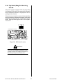
c. Locate the ground stud and remove the top nut
and washer.
d. Install a lug terminal on the ground wire.
e. Place the ground wire onto the ground stud
and secure with the nut and washer.
f. Insert the other two wires into the L1 and L2
terminals on the contactor.
g. Tighten all set screws even the ones not used.
AC Input
Power Cable
L1
L2
GND
Input Contactor
A-00915
Figure 3-7 Primary Power Cable Connections -
Single-Phase Operation
3.08 Gas Connections
A. Gas Requirements
WARNING
This unit not to be used with oxygen (O
2
).
Gases: Compressed Air or Nitrogen (N
2
) Only
Pressure: 70 psi (4.8 bar)
CAUTION
Maximum input gas pressure must not exceed 125
psi (8.6 bar)
Flow: Cutting - 400 scfh (188.7 lpm)
Gouging - 400 scfh (188.7 lpm)
La page est en cours de chargement...
La page est en cours de chargement...
La page est en cours de chargement...
La page est en cours de chargement...
La page est en cours de chargement...
La page est en cours de chargement...
La page est en cours de chargement...
La page est en cours de chargement...
La page est en cours de chargement...
La page est en cours de chargement...
La page est en cours de chargement...
La page est en cours de chargement...
La page est en cours de chargement...
La page est en cours de chargement...
La page est en cours de chargement...
La page est en cours de chargement...
La page est en cours de chargement...
La page est en cours de chargement...
La page est en cours de chargement...
La page est en cours de chargement...
La page est en cours de chargement...
La page est en cours de chargement...
La page est en cours de chargement...
La page est en cours de chargement...
-
 1
1
-
 2
2
-
 3
3
-
 4
4
-
 5
5
-
 6
6
-
 7
7
-
 8
8
-
 9
9
-
 10
10
-
 11
11
-
 12
12
-
 13
13
-
 14
14
-
 15
15
-
 16
16
-
 17
17
-
 18
18
-
 19
19
-
 20
20
-
 21
21
-
 22
22
-
 23
23
-
 24
24
-
 25
25
-
 26
26
-
 27
27
-
 28
28
-
 29
29
-
 30
30
-
 31
31
-
 32
32
-
 33
33
-
 34
34
-
 35
35
-
 36
36
-
 37
37
-
 38
38
-
 39
39
-
 40
40
-
 41
41
-
 42
42
-
 43
43
-
 44
44


ESAB PakMaster™ 100 XL™ Plus Air Plasma Cutting Power Supply Manuel utilisateur
- Catégorie
- Système de soudage
- Taper
- Manuel utilisateur
dans d''autres langues
Documents connexes
-
 Thermal Dynamics PakMaster™ 100 XL™ Plus Air Plasma Cutting Power Supply Manuel utilisateur
-
 Thermal Arc Inverter Arc Welder Model 400GTS CC/Tig Manuel utilisateur
-
 Firepower Plasma Cutting Power Supply Firepower™ PC-800 Manuel utilisateur
-
 Firepower Plasma Cutting Power Supply Firepower PC-500 Manuel utilisateur
-
ESAB DRAG-GUN™ Plasma Cutter with Built-In Air Manuel utilisateur
-
 Thermal Dynamics Plasma Cutting System PAK 10 Manuel utilisateur
-
-
Thermal Dynamics Thermal Dynamics an ESAB Brand Cutmaster 40 PLASMA CUTTING SYSTEM Manuel utilisateur


